STUDY AIR FLOW DISTRIBUTION IN THE DRYER SYSTEM THROUGH CFD SIMULATION
ABDULRAHMAN TAHER AHMED ANAAM
STUDY AIR FLOW DISTRIBUTION IN THE DRYER SYSTEM THROUGH CFD SIMULATION
ABDULRAHMAN TAHER AHMED ANAAM
This report is submitted
in fulfillment of the requirement for the degree of Bachelor of Mechanical Engineering (Thermal and Fluids)
Faculty of Mechanical Engineering
UNIVERSITI TEKNIKAL MALAYSIA MELAKA
ii
DECLARATION
I declare that this project report entitled “Study Air Flow Distribution In The Dryer System Through CFD Simulation” is the result of my own work except as cited in the references
iii APPROVAL
I hereby declare that I have read this project report and in my opinion this report is sufficient in terms of scope and quality for the award of the degree of Bachelor of Mechanical Engineering (Thermal & Fluids ).
iv
DEDICATION
v ABSTRACT
vi
ACKNOWLEDGEMENT
vii CONTENT
CHAPTER CONTENT PAGE
DECLARATION ii
APPROVAL iii
DEDICATION iv
ABSTRACT v
ACKNOWLEDGEMENT vi
CONTENT vii
LIST OF FIGURES xi
LIST OF TABLES xiii
CHAPTER 1 INTRODUCTION 1
1.1 Background 1
1.2 Problem Statement 3
1.3 Objective 4
1.4 Scope of Project 4
1.5 General Methodology 4
CHAPTER 2 LITERATURE REVIEW 7
2.1 Computational Fluid Dynamics 7 2.2 Designs of the drying chamber 8 2.3 Drying uniformity in the drying chamber 15
CHAPTER 3 METHODOLOGY 18
3.1 Introduction 18
3.2 Up staging trays design 19
viii
CHAPTER 4 RESULTS AND ANALYSIS 23
4.1 Mesh 23
4.2 Set up 28
4.3 Mesh adaption 32
4.4 Results 45
4.4.1 Three column-one level design 45
4.4.2 Up-staging design 49
4.4.3 Three column-tilted trays design 52
4.4.4 Summary 55
CHAPTER 5 CONCLUSION AND RECOMMENDATION 56
5.1 Conclusion 56
5.2 Recommendation 56
ix
LIST OF FIGURES
FIGURE TITLE PAGE
1.1 Drying system. 2
1.2 Draying chamber 3
1.3 The drying chamber, and in the middle, is the trays. 4
1.4 Flow chart of the methodology 6
2.1 Hybrid solar thermal drying system. 10
2.2 Variations in the tray and ambient temperatures with drying time.
11
2.3 The process layout. 12
2.4 Diagram of the heat exchanger 12
2.5 Schematic diagram of the drying cabinet. 13
2.6 Schematic of the dryer. 14
2.7 Sensors position. 15
2.8 Velocity from simulation and predicted drying rate for each tray.
16
3.1 Up staging trays design. 19
3.2 Three column-one level trays design 20
x
3.4 Three column-tilted trays design 22
4.1(a) Three column-one level trays design number of nodes, elements, and the mesh metric of the skewness statistics.
24
4.1(b) Three column-one level trays design mesh metric of the aspect ratio statistics.
24
4.1(c) Three column-one level trays design mesh control tree. 24
4.2 General mesh of up-staging trays design. 25
4.3(a) Up staging trays design number of nodes, elements, and the mesh metric of the skewness statistics.
25
4.3(b) Up staging trays design mesh metric of the aspect ratio statistics.
25
4.4 Edges sizing 3 26
4.5(a) Three column-tilted trays design number of nodes, elements, and the mesh metric of the skewness statistics.
26
4.5(b) Three column-tilted trays mesh metric of the aspect ratio statistics.
26
4.5(c) Three column-tilted trays mesh control tree. 26
4.6(a) Edge Sizing 27
4.6(b) Edge Sizing 2 27
4.7 Edges sizing 3 27
4.8(a) Two column-one level trays design number of nodes, elements, and the mesh metric of the skewness statistics.
28
4.8(b) Two column-one level trays design mesh metric of the aspect ratio statistics.
28
4.8(c) Two column-one level trays design mesh control tree. 28
4.9 Scaled residuals of three column-one level trays design 29
xi
4.11 Scaled residuals of three column-tilted trays 31
4.12(a) Velocity gradient marked cells of three column-one level design
33
4.12(b) Velocity gradient marked cells of up-staging design 33
4.12(c) Velocity gradient marked cells of three column-tilted trays design
34
4.13(a) Temperature gradient marked cells of three column-one level design
34
4.13(b) Temperature gradient marked cells of up-staging design 35
4.13(c) Temperature gradient marked cells of three column-tilted trays design
35
4.14(a) Region marked cells of three column-one level design 36
4.14(b) Region marked cells of up-staging design 36
4.14(c) Region marked cells of three column-one level design 37
4.15(a) combination of the marked cells of three column-one level design
38
4.15(b) combination of the marked cells of up-staging design 39
4.15(c) combination of the marked cells of three column-tilted trays design.
39
4.16(a) Three column-one level design velocity magnitude 41
4.16(b) Three column-one level design static temperature. 42
4.17(a) Up-staging design velocity magnitude 42
4.17(b) Up-staging design static temperature 43
4.18(a) Three column-tilted trays design velocity magnitude 43
4.18(b) Three column-tilted trays design static temperature 44
xii
4.20 Velocity streamlines of three column-one level design. 46
4.21 Average velocity plane. 46
4.22 Average velocity of three column-one level design. 48
4.23 Velocity streamlines of up-staging design. 49
4.24 Temperature contour of up-staging design. 50
4.25 Average velocity of up-staging design. 51
4.26 Velocity streamlines of three column-tilted trays design. 52
4.27 Temperature contour of three column-tilted trays design. 53
xiii
LIST OF TABLES
TABLE TITLE PAGE
2.1 Velocity of experimental and simulation result 16
4.1 Front line coordinates. 32
4.2(a) Coordinates of the selected region of three column-one level design
37
4.2(b) Coordinates of the selected region of up-staging design 37
4.2(c) Coordinates of the selected region of three column-one level design
38
4.3(a) Changes in nodes and faces after the mesh adaption of three column-one level design
40
4.3(b) Changes in nodes and faces after the mesh adaption of up-staging design
40
4.3(c) Changes in nodes and faces after the mesh adaption of three column-tilted trays design.
40
4.4 Trays average velocity of three column-one level design.
47
4.5 Trays average velocity of up-staging design. 50
4.6 Trays average velocity of three column-tilted trays design.
53
1
CHAPTER 1
INTRODUCTION
1.1 Background
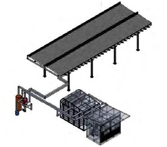
Drying process is one of the most important methods to preserve the agricultural materials such as food, wood, rubber, etc. It is a method that has been used along the lifetime of the homoserines. Drying process is method where it includes dehydration that involves the simultaneously application of heat and removal of moisture from crops or foods so that it’s easier to be preserved, stored, and marketed. Heat transfer involves in moving the heat from the heating medium to the point at which evaporation occurs. Once the moisture has been evaporated, the vapors produced must be transported through the product structure to the surrounding medium. This process involves air flow through the structure during the dehydration process. Many factors can cause food spoilage and these factors cannot occur without the moisture (Misha .S, 2013).
One of the traditional ways of drying is spreading the agricultural materials on a wide space where it will be exposed directly to the sunlight. This method of drying these materials is very difficult to control. As well as there are many factors for these materials to take a longer time than it supposed to be and these materials might not be able to be used anymore because of wind, birds, animals, require a large space, etc.
2
Figure1.1: Drying system. (Misha .S, 2013)
3
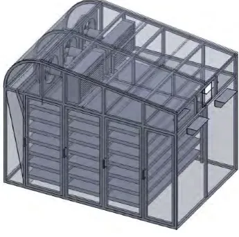
Figure 1.2: Drying chamber. (Misha .S, 2013)
1.2 PROBLEM STATEMENT
4
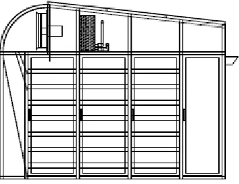
Figure1.3: The drying chamber, and in the middle, is the trays, (Misha .S,2013)
1.3 OBJECTIVE
The objectives of this project are as follows:
1. To modify the existing trays positions in the drying chamber.
2. Investigate the air flow distribution in the drying chamber using Computational Fluid Dynamics (CFD) software.
3. To predict the drying uniformity on each one of the trays,
1.4 SCOPE OF PROJECT
The scopes of this project are:
1. Re-locating or re arranging the trays using ANSYS.
2. A simulation of air stream lines, air distribution, and air velocity on the new re-located trays using ANSYS.
3. Observation of air distribution on the re-arranged tray using ANSYS. 4. Find the average velocity of air above the product.
5. Perfect the drying rate of each tray.
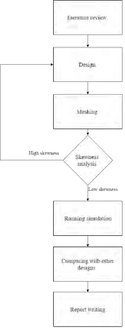
1.5 GENERAL METHODOLOGY
5 1. Literature review:
Journals, articles, or any materials regarding the project will be reviewed.
2. Design:
Develop the model. Sketch the new trays with specific dimension, choosing the new location.
3. Running Simulation:
Visualization of simulation of air distribution. 4. Analysis and comparing:
Analysis will be carried out on how hot air is distributed on the trays for all the different designs that will be presented. Comparing the results of each design to each other and suggest the best design based on the results presented.
5. Report writing:
A report on this study will be written at the end of the research.
6
7
CHAPTER 2
LITERATURE REVIEW
In this chapter, the most important journals will be reviewed as well as some will be referenced. This is done to have a clearer image about the future of this project and to have a better understanding of the theories.
2.1 Computational Fluid Dynamics
It can be very dangerous, expensive, time consuming and difficult for most of the experiments to run in order to find the results for the specific parameters, especially putting in consideration the error percentage for a large scale solar drying chamber and its trays as well as repositioning them to get the results (Misha .S, 2013). Computational fluid dynamics (CFD) simulation is widely used because of its ability to solve complicated equations for the conservation of momentum, energy, and mass using numerical methods to find and predict each of the pressure profiles, velocity, temperature at any point or any position needed in the drying chamber. Computational fluid dynamics (CFD) is used in this project to simulate the velocity and temperature profiles at each tray in the drying chamber, as well as the fluid pressure if required (Misha .S, 2013).
8 2.2 Designs of the drying chamber
The design of the drying chamber is very important due to its capability to affect the airflow distribution. Designing and locating the trays as well as placing them in a pattern is just as important as the design of the drying chamber itself. This is because placing the trays at the exact proper position, and having them positioned in the proper pattern can help reduce the drying time and drying uniformity at each tray. Normally, trays that are far from the source will take longer time to get dried.
Drying is the process of mass transfer and heat to remove the water or any other solvent by evaporation from a liquid, solid, or semi-solid. Typically, hot air stream is applied to dry any material, and usually the drying process is separated into two phases. In the first phase, the surface and inner side of the item have the same dampness content at first. The surface of the product or the material will be saturated with vapour when it gets heated by hot air, and then the water will evaporate. In the second phase, when the material surface gets dried, the moisture will slowly move from the inner side of the material to the outer surface, having it exposed to the dry airflow and high temperature to evaporate that moisture. Be that as it may, a few materials do not go through neither of the first or second phases. Belessiotis and Delyannis (2011) are characterized under another phase. On the third phase, for hygroscopic materials where the dampness content keeps on evaporating until the material accomplish its equilibrium stage. However, most materials quit drying before this phase.
9
Utilizing an alternate drying process, a similar item demonstrated critical impacts in surface, shading, and supplement content (Misha .S, 2012)
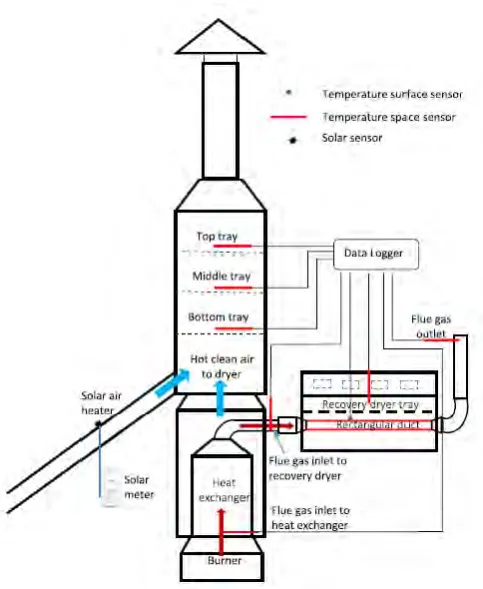
The hybrid solar thermal drying system in the present work was developed from a mixed mode common convection solar dryer, regular convection thermal back up unit, and recuperation dryer (Tadahmun A. Yassen, 2016). The mixed mode regular convection solar crop-dryer is possibly best and it seems, by all accounts, to be especially encouraging in tropical moist zones where climatic conditions support sun drying of agrarian items. The regular convection sun powered dryer was built from single pass twofold stream sun based air radiator with the roughened safeguard plate and drying chamber. The recuperation dryer was a half breed dryer built from an immediate sort regular convection sunlight based dryer and rectangular conduit. The warm go down unit involves gas-to-gas warm exchanger and fuel burner. (Tadahmun A. Yassen, 2016)
10
Figure2.1:Hybrid solar thermal drying system. Source: (Tadahmun A. Yassen, 2016)
[image:24.595.197.439.69.364.2]