Int. J. Electrochem. Sci., 7 (2012) 1852 - 1863
International Journal of
ELECTROCHEMICAL
SCIENCE
www.electrochemsci.org
An Efficient Sensor for Determination of Concentrated
Hydrogen Peroxide Based on Nickel Oxide Modified Carbon
Paste Electrode
Reza Ojani1,*, Jahan-Bakhsh Raoof 1, Banafsheh Norouzi1,2
1
Electroanalytical Chemistry Research Laboratory, Faculty of Chemistry, Mazandaran University, Postal Code: 47416-95447, Babolsar, Iran.
2
Department of chemistry; Faculty of Industry and Engineering; Islamic Azad University Ghaemshahr Branch, Ghaemshahr, Iran.
*
E-mail: [email protected]
Received: 12 August 2010 / Accepted: 20 January 2011 / Published: 1 March 2012
A new sensor for the analytical determination of hydrogen peroxide is proposed. This sensor was constructed by immobilizing nickel oxide film on the surface of carbon paste electrode, which was performed by derivatization of nickel hexacyanoferrate (NiHCF) in alkaline solution. Cyclic voltammetry experiments yielded evidence that nickel oxide facilitates hydrogen peroxide oxidation, showing excellent catalytic activity. Electrocatalytic oxidation of hydrogen peroxide occurs at a potential less positive than unmodified carbon paste electrode. This modified electrode has many advantages such as simple preparation procedure, good reproducibility and catalytic activity toward the hydrogen peroxide oxidation. Such characteristics were explored for the specific determination of hydrogen peroxide in cosmetics product sample, giving results in excellent agreement with those obtained by standard method.
Keywords: Nickel hexacyanoferrate, modified electrode, hydrogen peroxide, nickel oxide, electrocatalytic oxidation
1. INTRODUCTION
Also, all the electrochemical methods reported for determination of concentrated hydrogen peroxide are based on platinum-based electrodes [1, 8].
Nickel and nickel-based chemically modified electrodes such as nickel-hexacyanoferrates, hydroxides and complex modified nickel-electrodes have been utilized for a variety of electrooxidation [9-13] and reduction [14] purposes. Electrochemical studies using nickel-based electrodes have established that various electroreactant species can be determined with a high rate of heterogeneous electron transfer, good sensitivity, and reproducibility. In these studies, the presence of various Ni-based surface species has been detected, and extensive analysis of the composition of the nickel oxide films on the electrodes has been performed [15-17]. The anodic behavior of nickel in alkaline media has also been studied [18, 19] and formations of nickel oxide as well as nickel oxy-hydroxide and various phases of the species have been reported. The formation of nickel oxide has been achieved in principle in four different ways: potentiostatic and galvanostatic anodic sweeps, cathodic deposition of a pH-controlled salt of nickel in alkaline solution, and the electrode processing of a pre-crystallized nickel salt in alkaline solutions [10, 12] and derivatization of NiHCF [20] in alkaline solutions. In all of these studies, the layer consisting of NiOOH / Ni(OH)2 was detected.
In our previous works, we used the advantageous features of polymer modification, dispersion of metallic particles into organic polymers and carbon paste technology. Nickel ions were incorporated into the polymeric matrix by immersion of the polymeric modified electrodes in a nickel chloride solution. These electrodes were used for electrocatalytic oxidation of various carbohydrates [21, 22], methanol [23-26] and ethanol [27]. Also, we used of other modified electrode for electrooxidation and determination of hydrogen peroxide [28].
In this communication, we report the results of the catalysis of nickel oxide, obtained through surface derivatization of NiHCF on a carbon paste electrode (CPE), on electrooxidation of hydrogen peroxide known to be not easily oxidizable. Comparison of the collected on the above with reported information is made wherever possible.
2. EXPERIMENTAL PART
2.1.Reagents and materials
The solvent used in this work was twice distilled water. The Nickel chloride, Potassium hexacyanoferrate (ІІІ) and total chemical reagents from Fluka were used as received. Sodium hydroxide and hydrogen peroxide used in this work were analytical grade of Fluka origin and used without further purification. High viscosity paraffin (density = 0.88 g cm−3) from Fluka was used as the pasting liquid for the carbon paste electrode. Graphite powder (particle diameter = 0.10 mm) from Merck was used as the working electrode (WE) substrate. All other reagents were of analytical grade.
2.2. Preparation of working electrode
tube (internal radius = 1.7 mm). The electrical connection was implemented by a copper wire lead fitted into the glass tube. A fresh electrode surface was generated rapidly by extruding a small plug of the paste and smoothing the resulting surface on white paper until a smooth shiny surface was observed.
The precursor modification of the carbon paste electrode with NiHCF was achieved by cycling the electrode between 0 and 1 V at 50 mV s-1 for 6 min in a clear solution of 0.01 M NiCl2 in 0.01 M K3[Fe(CN)6] + 0.1 M KCl. Then the electrode with NiHCF film is cycled between 0 and 0.65 V in 0.1 M NaOH 9 times. On cycling the NiHCF electrode in alkaline solution Ni(OH)2 NiOOH film is formed which was identified by its characteristic cyclic voltammetric peak potential data [29]. CPE derivatized thus was found to be extremely stable for two weeks and it lasted for several hundreds of cycles.
2.3. Instrumentation
The electrochemical experiments were carried out using a Metrohm potentiostat/galvanostat model 764 VA trace analyzer instrument. Voltammetry was conducted using a three-electrode cell. A CPE, a platinum electrode and Ag|AgCl|KCl (3M) were used as working electrode, counter electrode and reference electrode respectively.
3. RESULTS AND DISCUSSIONS
[image:3.596.161.436.528.722.2]3.1. Electrochemical behavior of the NiHCF – modified carbon paste electrode
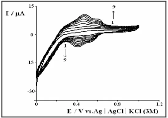
Fig. 1 shows the typical cyclic voltammograms describing the deposition process of NiHCF.
The formation and growth of NiHCF film on a carbon paste electrode is verified by two pair of redox peaks at about 0.44 and 0.58 V, which grows with potential-scan cycling repetitively. The two redox peaks/waves can be ascribed to the Fe(CN)63-/4- transition in the NiHCF [30] which can be described as: Ni1.5II[FeΙΙI(CN)6]/ KNi1.5II[FeΙΙ (CN)6] and KNiII[FeΙΙI(CN)6] /K2NiII[FeΙΙ(CN)6].
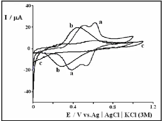
[image:4.596.158.437.342.551.2]Fig. 2 presents comparative cyclic voltammograms for the NiHCF-modified CPE in three kinds of solutions with different supporting electrolytes. It is well known that metal hexacyanoferrate films are permeable membranes for cations [31-34]. These alkali metal cations can react with the inorganic film by incorporation into their net structures. For the NiHCF-modified CPE, NiHCF supported on carbon paste acts as a zeolite in which hydrated cations may enter into the cage. Potassium cation can be expected to fit within the zeolite cage more easily than other cations. The cyclic voltammograms of the NiHCF film on carbon paste electrodes and then transferred to aqueous solutions with the same cations and different anions are compared. The cyclic voltammograms almost overlap and the peak heights are close (not shown). The anion dependence is not obvious for the electrode modified with the NiHCF redox couple.
Figure 2. Cyclic voltammograms of a NiHCF film synthesized from 0.1 M aqueous KCl solution on the carbon paste electrode, which was then transferred to 0.1 M aqueous solution of (a) KCl, (b) NaCl and (c) HCl, v = 50 mV s-1.
indicates diffusion-controlled processes, which may be related to the relatively slow diffusion of potassium ions into the electrode wetting.
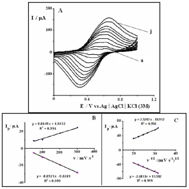
[image:5.596.107.491.203.587.2]Also, we have observed two pair peaks at lower scan rate (< 100 mV s-1) but one pair redox peak at higher scan rate. The peak-to-peak separation increase with scan rate and potential separation between anodic and cathodic peaks is non-zero (ΔEp = 0 expected for a reversible surface redox process) which might arise due to non-ideal behavior.
Figure 3. Scan rate dependence of the peak current for carbon paste electrode modified with NiHCF, scan rates: (a) 50, (b) 100, (c) 200, (d) 300, (e) 400, (f) 500, (g) 600, (h) 700, (i) 900 and (j) 1000 mV s-1 in 0.1 M KCl solution (A), Plot of Ip vs. v (B) and Plot of Ip vs. v1/2 (C).
3.2. Electrochemical behavior of the nickel oxide film
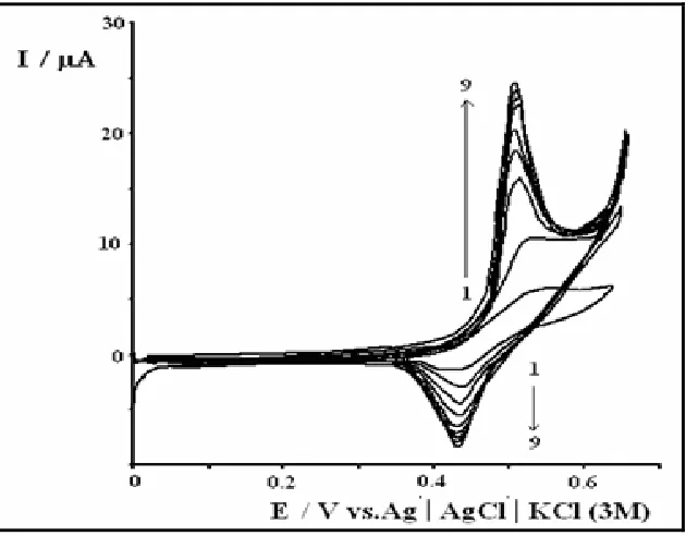
is observed. The anodic and cathodic peaks occur at 0.43 and 0.50 V respectively. The redox reaction of this derivatised oxide electrode is presented as follows:
Ni(OH)2 + OH- NiOOH + H2O + e - (1)
[image:6.596.142.457.257.503.2]The current grows with the number of potential scans, indicating the progressive enrichment of the electroactive species Ni(OH)2 and NiOOH in the surface. The change of anodic peak potential with increasing the number cycles was because of alterating in phase composition of nickel oxides. At potentials positive of 0.60 V, there is a sharp rise in anodic current due to oxygen evolution.
Figure 4. Electrochemical response of a NiHCF-modified electrode in 0.1 M NaOH and during nine consecutive potential scan, v = 50 mV s-1.
Fig. 5 represents the cyclic voltammograms of the electrode modified with nickel oxide in 0.1 M NaOH at different scan rates. The anodic and cathodic peaks occur at 0.52 and 0.44 V at a scan rate of 50 mV s-1. The anodic peak potential shifted towards the positive direction with increasing scan rates, while the cathodic peak shifted to a more negative potential. For example, a peak potential separation of 0.08 and 0.136 V were observed at 50 and 300 mV s-1 respectively. Also, the anodic and cathodic peak currents increase linearly with scan rate as predicted for a diffusionless system (Fig. 5B). The surface coverage Γ* of the redox species of nickel oxide was determined from the slope of these lines and using the following equation [35]:
Where Ip is the peak current, A is the electrode surface area and Γ* is the surface coverage of the redox species and taking the average of both cathodic and anodic currents, the surface coverage of the immobilized film was obtained 2.93×10⁻⁹
mol cm-2. This surface concentration would correspond to a thickness of a few hundreds of monolayers.
[image:7.596.165.433.171.370.2]
Figure 5. Cyclic voltammograms of CPE modified with nickel oxide at different scan rates: (a) 50, (b) 100, (c) 160, (d) 200, (e) 300, (f) 400, (g) 600, (h) 800 and (i) 1000 mV s-1 in 0.1 M NaOH solution (A), Plot of Ipa vs. v (B).
[image:7.596.175.422.464.671.2]
3.3. Electrooxidation of hydrogen peroxide on the modified electrode
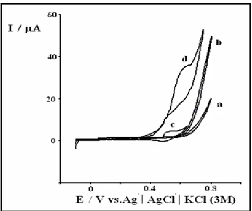
In this work, in order to investigate whether the CPE modified with nickel oxide has excellent electrocatalytic property, control experiments were carried out by using bare CPE and CPE modified with nickel oxide. Voltammetric responses of these electrodes with addition of 4 mM hydrogen peroxide are presented in Fig. 6. As shown in Fig. 6, no obvious response can be observed at bare CPE (Fig. 6 curve b), which shows that it is difficult for hydrogen peroxide to be oxidized at bare CPE.
If the CPE coated with nickel oxide and placed into the same hydrogen peroxide containing cell, a well defined and reproducible peak is observed (Fig. 6 curve d). The oxidation peak potential of hydrogen peroxide on CPE modified with nickel oxide is about 0.6 V. The significant decrease of overpotential (> 200 mV) during electrooxidation of hydrogen peroxide demonstrates that CPE modified with nickel oxide has a good catalytic activity toward the hydrogen peroxide oxidation as follows (EC′ mechanism):
2 Ni(OH)2 2 NiOOH + 2 H+ + 2 e- (3)
2 NiOOH + H2O2 O2 + 2 Ni(OH)2 (4)
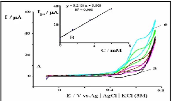
Also, redox process is affected by the presence of hydrogen peroxide in bulk solution. The response of CPE modified with nickel oxide to hydrogen peroxide was examined and the corresponding calibration curves are shown (Fig. 7 and Fig. 8). Two linear ranges from 0.6 to 6 mM and 17 to 54 mM (LOD (2δ) = 0.34 mM) have been observed for modified electrode. We ascribe this to a change in the catalytic reaction conditions arising from the formation of oxygen gas bubbles at the surface of modified electrode, as has already been reported [36-38].
[image:8.596.155.443.522.692.2]
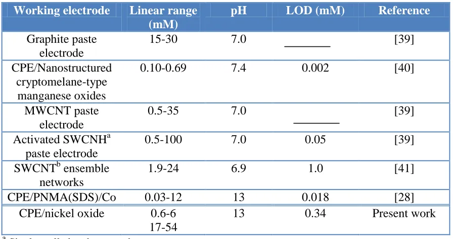
Table 1. Comparison of the efficiency of some mediators used in electrocatalysis of hydrogen peroxide oxidation
Working electrode Linear range (mM)
pH LOD (mM) Reference
Graphite paste electrode
15-30 7.0 [39]
CPE/Nanostructured cryptomelane-type
manganese oxides
0.10-0.69 7.4 0.002 [40]
MWCNT paste electrode
0.5-35 7.0 [39]
Activated SWCNHa paste electrode
0.5-100 7.0 0.05 [39]
SWCNTb ensemble networks
1.9-24 6.9 1.0 [41]
CPE/PNMA(SDS)/Co 0.03-12 13 0.018 [28]
CPE/nickel oxide 0.6-6 17-54
13 0.34 Present work
a
Single-walled carbon nanohorn b
Single-walled carbon nanotube
Indeed at low concentrations of hydrogen peroxide, the formed gas being negligible has no effect on the diffusion of hydrogen peroxide toward electrode surface. However, at high concentrations of hydrogen peroxide, gas evolution at the electrode surface reduces to some extent the normal diffusion of the substrate.
Also, the electrocatalytic oxidation of hydrogen peroxide in this work has been compared with other research work (Table 1). The results show that CPE modified with nickel oxide is suitable electrode in comparison with other pervious mediators.
[image:9.596.161.436.529.711.2]
3.4. Analysis of hydrogen peroxide in real sample
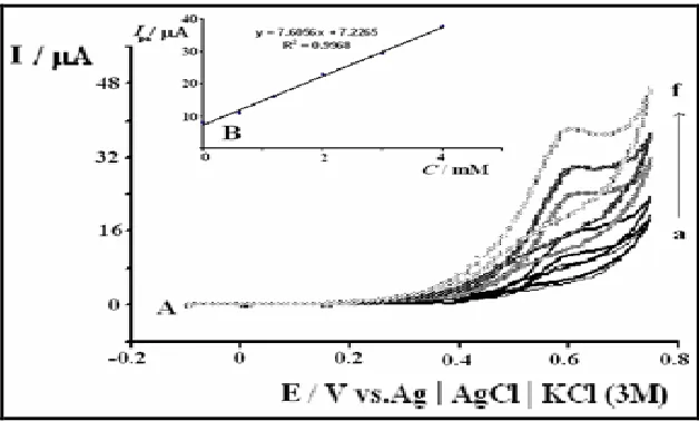
[image:10.596.141.455.243.432.2]The new method based on the CPE modified with nickel oxide was employed for the quantification of hydrogen peroxide in some commercial samples of cosmetics products. The determination of hydrogen peroxide in a sample was carried out by the standard addition method for prevention of any matrix effect. Fig. 9A shows the related voltammograms for this purpose. As can be seen in this Figure, adding hydrogen peroxide to the solution of 3×10³ order diluted cosmetics products in the presence of 0.1 M NaOH (curve a) caused an increase in the oxidation peak height (curves b-f). Thus, the peak was attributed to hydrogen peroxide.
Figure 9. Cyclic voltammograms: (a) CPE modified with nickel oxide + 3×10³ order diluted solution of cosmetics products in 0.1 M NaOH solution, (b-f) after adding hydrogen peroxide 0.6, 1.2, 2.0, 3.0 and 4.0 mM, respectively; v = 20 mV s-1 (A); Plot of Ipa as a function of added hydrogen peroxide concentration to sample (B).
Also Fig. 9B is a diagram of Ipa versus hydrogen peroxide concentration that shows the linear region usable for determination of hydrogen peroxide. By this method hydrogen peroxide concentration in real sample was about 2.9 M. Accuracy was examined by comparison of data obtained from this method with a recognized common method for determination of hydrogen peroxide (oxidation-reduction titration in acid solution of KMnO4). The results from the statistical calculation indicate good agreement between the mean values (t-test) and precision (F-test) for two methods (for p = 0.05).
4. CONCLUSIONS
linearity between the electrooxidation current and the concentration of hydrogen peroxide makes it practically usable in determining concentrated hydrogen peroxide. Our study shows that CPE modified with nickel oxide is promising alternative to platinum electrode that conventionally used for determination of concentrated hydrogen peroxide. This modified electrode was used for the quantification of hydrogen peroxide in commercial samples of cosmetics product giving excellent analytical results.
References
1. S.A.G. Evans, J.M. Elliott, L.M. Andrews, P.N. Bartlett, P.J. Doyle, G. Denuault, Anal. Chem., 74 (2002) 1322.
2. S. Hrapovic, Y. Liu, K.B. Male, J.H.T. Luong, Anal. Chem., 76 (2004) 1083. 3. W.B. Nowall, W.G. Kuhr, Electroanalysis, 9 (1997) 102.
4. A.A. Karyakin, E.A. Puganova, I.A. Budashov, I.N. Kurochkin, E.E. Karyakina, V.A. Levchenko, V.N. Matveyenko, S.D. Varfolomeyev, Anal. Chem., 76 (2004) 474.
5. J. Wang, M. Musameh, Y. Lin, J. Am. Chem. Soc., 125 (2003) 2408.
6. B. Sljukic, C.E. Banks, A. Crossley, R.G. Compton, Electroanalysis, 18 (2006) 1757.
7. L. Gorton, A. Lindgren, T. Larsson, F.D. Munteanu, T. Ruzgas, I. Gazaryan, Anal. Chim. Acta, 400 (1999) 91.
8. A. Kicela, S. Daniele, Talanta, 68 (2006) 1632.
9. A. Kowal, S.N. Port, R.J. Nichols, Catal. Today, 38 (1997) 483.
10.S. Majdi, A. Jabbari, H. Heli, J. Solid State Electrochem., 11 (2007) 601.
11.S. Majdi, A. Jabbari, H. Heli, A.A. Moosavi-Movahedi, Electrochim. Acta, 52 (2007) 4622.
12.M. Jafarian, M.G. Mahjani, H. Heli, F. Gobal, M. Heydarpoor, Electrochem. Commun., 5 (2003) 184.
13.A.A. El-Shafei, J. Electroanal. Chem., 471 (1999) 89.
14.J. Losada, I. del Peso, L. Beber, J. Electroanal. Chem., 447 (1998) 147. 15.B. MacDougall, M.J. Graham, Electrochim. Acta, 26 (1981) 705.
16.B. MacDougall, D.F. Mitchell, M.J. Graham, J. Electrochem. Soc., 132 (1985) 2895.
17.G.R. Fu, Z. Hu, L. Xie, X. Jin, Y. Xie, Y. Wang, Z. Zhang, Y. Yang, H. Wu, Int. J. Electrochem. Sci., 4 (2009) 1052.
18.B. MacDougall, J. Electrochem. Soc., 127 (1980) 789.
19.R.E. Hummel, R.J. Smith, E.D. Verink. Corros. Sci., 27 (1987) 803. 20.R. Vittal, H. Gomathi, G.P. Rao, J. Electroanal. Chem., 497 (2001) 47. 21.R. Ojani, J.B. Raoof, P. Salmany-Afagh, J. Electroanal. Chem., 571 (2004) 1. 22.R. Ojani, J.B. Raoof, S. Fathi, Electroanalysis, 16 (2008) 1727.
23.R. Ojani, J.B. Raoof, S.R. Hosseini, Electrochim. Acta, 53 (2008) 2402. 24.R. Ojani, J.B. Raoof, S. Fathi, Electrochim Acta, 54 (2009) 2190.
25.R. Ojani, J.B. Raoof, S. Fathi, J. Solid State Electrochem., 13 (2009) 927. 26.J.B. Raoof, M. Jahanshahi, S. Momeni, Int. J. Electrochem. Sci., 5 (2010) 517. 27.J.B. Raoof, R. Ojani, F. Monfared, J. Electroanal. Chem., 633 (2009) 153. 28.R. Ojani, J.B. Raoof, B. Norouzi, J. Solid State Electrochem., 14 (2010) 621. 29.J. Joseph, H. Gomathi, G. P. Rao, Sol. Energy Mater., 23 (1991) 19.
30.J. Bacskai, K. Martinusz, E. Czirok, G. Inzelt, P.J. Kulesza, M.A. Malik, J. Electroanal. Chem., 385 (1995) 241.
31.H. Kahlert, U. Retter, H. Lohse, K. Siegler, F. Scholz, J. Phys. Chem., B 102 (1998) 8757. 32.M.B. Soto, F. Scholz, J. Electroanal. Chem., 521 (2002) 183.
34.P. Wu, C. Cai, J. Electroanal. Chem., 576 (2005) 49.
35.A.J. Bard, L. R. Faulkner, Electrochemical Methods, Wiley, New York (2001). 36.U. Scharf, E.W. Grabner, Electrochim. Acta, 41 (1996) 233.
37.S.M. Golabi, H.R. Zare, J. Electroanal. Chem., 465 (1999) 168.
38.H. Razmi-nerbin, M.H. Pournaghi-Azar, J. Solid State Electrochem., 6 (2002) 126.
39.S. Zhu, L. Fan, X. Liu, L. Shi, H. Li, S. Han, G. Xu, Electrochem. Commun., 10 (2008) 695. 40.Y. Lin, X. Cui, L. Li, Electrochem. Commun., 7 (2005) 166.
41.J. Kruusma, V. Sammelselg, C.E. Banks, Electrochem. Commun., 10 (2008) 1872.