This is a repository copy of
Learning capsules for vehicle logo recognition
.
White Rose Research Online URL for this paper:
http://eprints.whiterose.ac.uk/136086/
Version: Accepted Version
Proceedings Paper:
Chen, R., Jalal, M.D.A., Mihaylova, L. orcid.org/0000-0001-5856-2223 et al. (1 more
author) (2018) Learning capsules for vehicle logo recognition. In: 2018 21st International
Conference on Information Fusion (FUSION). 2018 21st International Conference on
Information Fusion (FUSION), 10-13 Jul 2018, Cambridge, UK. IEEE , UK , pp. 565-572.
ISBN 978-0-9964527-6-2
10.23919/ICIF.2018.8455227
© 2018 ISIF. Personal use of this material is permitted. Permission from IEEE must be
obtained for all other users, including reprinting/ republishing this material for advertising or
promotional purposes, creating new collective works for resale or redistribution to servers
or lists, or reuse of any copyrighted components of this work in other works. Reproduced
in accordance with the publisher's self-archiving policy.
eprints@whiterose.ac.uk https://eprints.whiterose.ac.uk/
Reuse
Items deposited in White Rose Research Online are protected by copyright, with all rights reserved unless indicated otherwise. They may be downloaded and/or printed for private study, or other acts as permitted by national copyright laws. The publisher or other rights holders may allow further reproduction and re-use of the full text version. This is indicated by the licence information on the White Rose Research Online record for the item.
Takedown
If you consider content in White Rose Research Online to be in breach of UK law, please notify us by
Learning Capsules for Vehicle Logo Recognition
Ruilong Chen
a, Md Asif Jalal
b, Lyudmila Mihaylova
aand Roger K Moore
ba
Department of Automatic Control and Systems Engineering, University of Sheffield, S1 3JD, UK
bDepartment of Computer Science, University of Sheffield,S1 4DP, UK
{rchen3, majalal1, l.s.mihaylova and r.k.moore}@sheffield.ac.uk
Abstract—Vehicle logo recognition is an important part of vehicle identification in intelligent transportation systems. State-of-the-art vehicle logo recognition approaches use automatically learned features from Convolutional Neural Networks (CNNs). However, CNNs do not perform well when images are rotated and very noisy. This paper proposes an image recognition framework with a capsule network. A capsule is a group of neurons, whose length can represent the existence probability of an entity or part of an entity. The orientation of a capsule contains information about the instantiation parameters such as positions and orientations. Capsules are learned by a routing process, which is more effective than the pooling process in CNNs. This paper, for the first time, develops a capsule learning framework in the field of intelligent transportation systems. By testing with the largest publicly available vehicle logo dataset, the proposed framework gives a quick solution and achieves the highest accuracy (100%) on this dataset. The learning capsules have been tested with different image changes such as rotation and occlusion. Image degradations including blurring and noise effects are also considered, and the proposed framework has proven to be superior to CNNs.
Index Terms—Intelligent Transportation Systems, Vehicle Logo Recognition, Convolutional Neural Network, Capsule Network
I. INTRODUCTION
Recently Vehicle Logo Recognition (VLR) has become a popular research topic in intelligent transportation systems as vehicle logos are one of the most distinguishable marks on vehicles. Recognizing vehicle logos helps with vehicle identi-fication, traffic monitoring and vehicle management [1, 2]. For instance, fraudulent plates can be detected if the logo does not match its license plate. This could prevent crimes as replacing the plate is often associated with actions before a crime [3]. In addition, VLR could also provide guidance for autonomous driving systems and intelligent parking systems [4, 5].
Rather than using the raw pixel values and templates, hand-crafted features are often used to represent the content in an image [6]. Hand-crafted features can be separated as global features and local features. Global features consider all pixel values and generate a vector to represent an image, such as the Histogram of Oriented Gradients (HOG) method [7]. However, all pixel information embedded into the feature vector makes the feature not robust to shift, distortion and rotation. Local
features such as Scale Invariant Feature Transform (SIFT) [8], in contrast, only consider a few distinguishable areas of an image. In general, local features are more robust to challenging images [2]. Both local features and global features are widely used for VLR [1, 9–11]. Automatic extracted features by CNNs [12] are more advanced than hand-crafted features. The features learned by CNNs are becoming the mainstream in the field as its success on ImageNet [13] and they have been widely applied especially for solving the VLR task [5, 14]. However, research shows that CNNs fail in some conditions such as pixel value variations [15, 16].
A recent idea of capsule network has been proposed by Sabour et al [17] in order to deal with the limitations of CNNs. A capsule is a group of neurons, whose length represents the probability of the entity’s existence, and the orientation represents the instantiation parameters [17]. Compared with a convolutional process which transfers scalar inputs to scalar outputs, a capsule transfers data from a group of neurons to a group of neurons between adjacent capsule layers. Instead of using the max-pooling process which only finds the local respond from an individual layer, a routing process is applied in capsule networks in order to detect active capsules cross layers. Using a routing process, each capsule predicts the output of higher level capsules. A lower level capsule becomes active if its prediction agrees with the true output of higher level capsules using a inner product measurement. In the last fully connected capsule layer, weights are optimized by a margin loss function.
Fig. 1:An example of CNNs architecture.
against image changes and degradations than the state-of-the-art CNNs.
The rest of this paper is organized as follows. In Section II, methods based on CNNs capsule networks are introduced. Section III explains the proposed VLR classification framework based on the capsule network. Simulation results and discussions are presented in Section IV and Section V summaries the work.
II. CONSIDERED DEEP LEARNING APPROACHES
A. Convolutional Neural Network
Lecun et al. proposed the first CNN framework LeNet [18]. Different CNN frameworks have been developed quickly after the AlexNet [12] achieved the best performance on ImageNet in 2012. Unlike neural networks, where neurons in each layer are fully connected to neurons in the next layer, each layer in a CNN shares the weights by using convolutional kernels. This process tremendously decreases the number of weights when compared with neural networks; therefore, it can prevent the over-fitting problem, which is one of the main problems in neural networks [19]. Another advantage is that the spatial information of the content is preserved by the convolutional process, while neural networks simply reshape an image into a vector, without persevering the spatial information. CNN frameworks are mainly composed of the convolution operations and the pooling operations. Figure 1 illustrates a typical CNN framework.
In a convolution stage, feature maps are convoluted with different convolutional kernels, which are equivalent to filters in the field of image processing. Kernels can be regarded as the shared weights connecting two layers. Suppose kernels of size [a×b×n]([height ×width×depth]) are used, theith
(i = 1,2,· · · , n) convolutional feature map can be denoted as:
Ci=f
X
j
Vi∗ Ij
, (1)
where Vi is the ith
kernel and Ij (j = 1,2,· · · , J) is
the jth feature map (I
j can be a channel of the original
image, a pooling map and a convolutional map). Here f(·)
denotes a non-linear activation function and∗ represents the convolutional operation. The Rectified Linear Unit (ReLU), where g(x) =max(0, x), is often applied as the non-linear function [12].
A convolutional process is often followed by a pooling process. In the pooling operation, a pooling process decreases the size of the input feature maps, which can be regarded as a down-sampling operation. Each pooling map Pi is usually obtained by a pooling operation over the corresponding con-volutional mapCi:
Pi=pool(Ci), (2)
where pool(·) represents a pooling method [14]. A window shifts on the previous map Ci and the mean value (or the maximum value) in each window is extracted in order to form a pooling map Pi.
size of [3× 3]. The Google-Net [22] even increased the number of layers to 22 and applied the inception module, in which different convolutional feature maps (generated by convolutional kernels of different sizes) and the pooling feature maps were combined together. The Res-Net [23] built a 152 layer architecture and introduced the idea of the residual learning, which built short-cut connections between layers and achieved the best result on ImageNet in 2015.
B. Capsule Network
In CNNs, connections between layers and layers are scalar-scalar. However, in a capsule network, a group of neurons are combined in order to present an entity or part of an entity. Therefore, a neuron is replaced with a group of neurons and the connections between capsule layers become to vector-vector. For each capsule (represented as a vector), a non-linear squash functionf(·)is defined:
f(x) = ||x|| 2 2
1 +||x||22 x
||x||2, (3)
withx is the input vector of the squash function and|| · ||is the l2-norm. This function makes the length of short vectors shrink close to 0 and long vectors shrink close to 1. Hence, the output length can be used to represent the probability that an entity exists. The output of the capsulej (vj) is given by:
vj=f(hj), (4)
where hj is the input of the capsule j. Parameters in each capsule represent various properties such as position, scale and orientation of a particular entity [17].
Excepting the capsules in the first capsule layer, the total input of the capsulehj is a weighted sum of all “predictions” oj|i (the predicted output of capsulej in the current layer by
the input capsule ifrom the previous layer) is given by:
hj =X
i
cijoj|i, (5)
wherecij are coefficients determined by a routing process. Let
qij denote the log prior probabilities that the capsulei(in the previous layer) is coupled with the capsule j (in the current layer); the coefficients cij can then be denoted as:
cij =Pexp(qij)
dexp(qid)
, (6)
where d is an index goes though all capsules in the current layer. qij are initialised with zeros and updated by a routing algorithm. In the routing algorithm, qij is updated by the following process:
q(ijr+1)=q
(r)
ij +
v
j,oj|i
, (7)
where r is an iteration index. Note, the term vj,oj|i is the inner product between the predicted output and its actual
output (of the capsulej in the current layer). The assumption is intuitive; for the capsulej in the current layer, all capsules from the previous layer will predict its value. If the prediction made by the capsule i from the previous layer is similar to the actual output vj, the capsule i should have a high probability of the contribution. Hence, the coupling coefficient
cij increases.
In equations (5) and (7), the predictions oj|i can be calcu-lated by the output capsulesui from the previous layer:
oj|i=Wijui, (8)
where Wij are transformation matrices connecting capsules between two adjacent layers.
Suppose there are C classes, then the final capsule layer hasC capsules, with the length of each capsule representing the existence probability of the corresponding object. To allow multiple classes exist in the same image, a margin loss is used, with the lossLi for the classi (i= 1,2,· · ·, C) is given by:
Li=yi max(0, m+− ||vi||2)2
+λ(1−yi)max(0,||vi||2−m−)2, (9)
whereyi= 1if and only if the object of the classiexists and
||vi||2is the length of the vectorvi in the final capsule layer. This encourages the length of the capsulevi to be abovem+ if an object of the classiis present, and encourages the length of the capsulevi to be belowm− when an object of the class
i is absent. Here λ is a controlling parameter and the total classification loss is calculated byP
iLi, which simply sums
the losses from all the final layer capsules.
In capsule networks, the back-prorogation is applied to update the convolutional kernels and the transformation matrices. A routing process is applied to update the weights for the coupling coefficients c and the log prior probabilities
q. In capsule networks, the vector-vector transformation could potentially extract more robust features than scalar-scalar transformation in CNNs.
III. PROPOSEDVLRFRAMEWORK
This paper develops a VLR recognition framework based on a capsule network. The general architecture as shown in Figure 2 contains two convolutional layers and a fully connected layer. The size of the first convolutional kernels is [21×21×128] ([height×width×depth]), and a convolution operation is applied with a stride of two, followed by a ReLU non-linear activation function. Hence, the output size of the convolutional 1 is [25×25×128].
Fig. 2: The proposed capsule network for VLR (similar to [17]).
with a stride of two. This process generates ten convolutional units, each of them is of the size [7×7×10]. These units are re-grouped into ten channels, each channel containing one layer from all convolutional units. Each channel is made up from 7×7 = 49capsules with each capsule being a vector with ten entries. The primary capsule layer connects with the final capsule layer by transformation matrices. This process is the same with a fully connected layer in neural networks, except the scalar-scalar transform is changed to a vector-vector transform.
The reconstruction loss is considered for the weights updating.The reconstruction process is a decoder using neural networks; the last capsule layer is connected 2 hidden layers and each hidden layer has 2048 neurons. The training process of the learning capsules is summarised in Algorithm 1. The routing process is applied only between the primary capsule layer and the final capsule layer. There are 7×7×10 = 490
capsules in the primary capsule layer and ten (C=10) capsules in the final capsule layer. This requires 4900 transformation matrices with the size of [10 ×30]. The length of each capsule in the final capsule layer represents the existence probability of the corresponding object.
IV. PERFORMANCEEVALUATION
In this section a CNN framework is designed. Figure 4 shows its designed structure. is applied for comparisons. The architecture contains three convolutional layers, three pooling layers and two fully connected layers. The reason of not using big CNN frameworks such as AlexNet [12] and VGG [21] is that there are too many parameters in big CNN frameworks, which cause over-fitting problems. Meanwhile, the developed CNN framework has proven to be a good model as it has achieved more than 99%accuracy on the testing dataset while containing much less parameters than in AlexNet and VGG.
Algorithm 1 The training process of the proposed learning capsule
Input:
Input images.
Number of iterationsrfor the routing algorithm.
Procedure:
1: A convolutional operation with ReLU is applied to the input images.
2: A convolutional operation is applied to the convolutional layer 1 using convolution kernel groups.
3: Reshape the primary capsule layer to capsulesui, eachui is squashed by the function in (3).
4: Define a final capsule layer.
5: Define a corresponding restoration network.
6: For all capsuleiin the primary capsule layer and capsule
j in the final capsule layer: initialiseqij to zeros.
7: forr iterationsdo
8: for all capsule i in the primal capsule layer, apply equations (6) and (8) in order to get cij andoj|i.
9: for all capsule j in the final capsule layer, apply equation (5) in order to get hj.
10: for all capsule j in the final capsule layer, apply equation (4) in order to get vj.
11: update all qij, apply equation (7).
return vj
12: end for
13: Calculate the loss and update the weights.
In the proposed capsule network, there are three iterations in the routing process.
Fig. 3: The capsule generation process in the proposed primary capsule layer.
[image:6.612.47.303.515.617.2]Fig. 4: The designed CNN architecture.
Fig. 5: The vehicle logo dataset.
and 150 testing images. All images are of the size [70×70]. Figure 5 shows an example of the ten vehicle categories by randomly choosing one testing image from each category.
The performance evaluation of both the CNN and the
proposed capsule network are conducted in Python on a laptop with the following specification: Intel I5 (3210M CPU 2.5GHz
×4), 8G RAM and an Nvidia GTX 1070 (extended GPU). The performance of each method is measured in terms of accuracy (percentage of correctly classified testing images). The model is trained on the training dataset with 100 epochs. In each training epoch, the corresponding testing accuracy is recorded in order to give more detailed results.
A. Performance of the proposed capsule network on the orig-inal testing dataset
0 20 40 60 80 100
Number of epochs
50 60 70 80 90 100
Accuracy (%)
CNN
[image:7.612.56.291.59.216.2]Capsule network
Fig. 6: The performance of the CNN and proposed capsule network on the original testing data.
at the100thepoch) and the capsule network (accuracies keep
at 100% after the 4th
epoch) can achieve good results after a limited number of epochs. Note that the developed capsule network achieved the highest accuracy on this dataset (100%). However, the advantage could not be significant as there is a limit space for the improvement. Hence, image degradations are applied to evaluate the trained CNNs and the capsule networks.
B. Performance on challenging data
In practice, we would not expect to always have clear logos in the images. As a result, here different image changes includ-ing rotation and occlusion, and different image degradations such as burring and noise effects are added to the testing images in order to examine the robustness of both the CNN and the proposed capsule network. Figure 7 shows the effects by adding these changes and degradations individually and together. The first image is an original testing image, the second image shows its rotated version with an angle of 50 degrees. The third image contains an rectangular box (with the size of 20% of the image’s width and height), whose pixel value is set to a random number between 0 to 255 in order to make an occlusion effect. An Gaussian smoothing kernel (with a standard deviation of two) is applied to the original testing image and its blurring effect is shown in the fourth image. Noise effect is illustrated in the fifth image by adding Gaussian noises with a standard deviation of 0.1. The last image is the combined effect by adding all the aforementioned image changes and degradations.
[image:7.612.315.559.65.111.2]In the real applications, these challenges are not always as serious as in Figure 7. Hence, three challenge testing datasets are created involving different levels of image changes and degradations. The challenge testing dataset 1 only considers the image noise. A zero-mean Gaussian noise with the variance
Fig. 7: From left to right are: a testing image, the rotation effect, the occlusion effect, the blurring effect, the noise effect and the combined effect, respectively.
of 0.1 is applied to the original testing dataset. The challenge testing dataset 2 only considers the image rotation by adding a random rotation angle on the original testing dataset within the range [−25◦,25◦]. The challenge testing dataset 3 considers the combined effects by adding the following contaminations on the original dataset: an random rotation within the angle
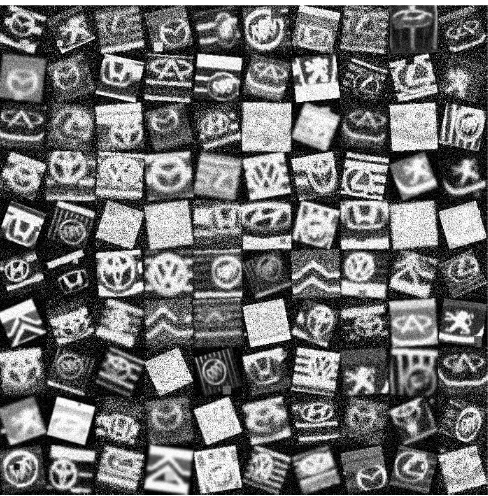
[image:7.612.316.560.372.620.2][−25◦,25◦], the occlusion (a maximum of 20%), blurring (with a maximum standard deviation of two) and the Gaussian white noises (variance is a random value in the range of [0, 0,1]). The value between the minimum and maximum is randomly generated following a uniform distribution. Figure 8 illustrates 100 random examples of the challenge testing dataset 2.
Fig. 8: A hundred random examples in the challenge testing dataset 2.
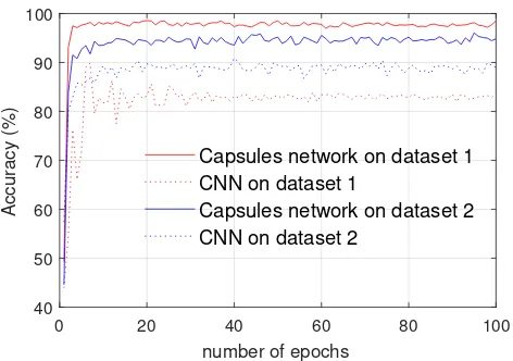
0 20 40 60 80 100
number of epochs
40 50 60 70 80 90 100
Accuracy (%)
Capsules network on dataset 1 CNN on dataset 1
[image:8.612.55.291.57.223.2]Capsules network on dataset 2 CNN on dataset 2
Fig. 9: The performance of the CNN and the proposed capsule network on the challenge testing dataset 1 and challenge testing dataset 2.
(challenge dataset 1), an accuracy of 85.75% is achieved at the 100th epoch. In contrast, the capsule network achieves
a high accuracy of 98.49% in the same scenario. For image rotations (challenge dataset 2), the capsule network and the CNN achieve accuracies of 94.82% and 89.00%, respectively. As shown in Figure 9, the real line is always above the dash line, which indicates the proposed capsule network is more robust to noise and rotation than the CNN.
0 20 40 60 80 100
Number of epochs 30
40 50 60 70
Accuracy (%)
CNN
[image:8.612.60.290.413.569.2]Capsule network
Fig. 10: The performance of the CNN and the proposed capsule network on the challenge testing dataset 3.
Figure 10 shows the accuracy of the CNN and the proposed capsule network on the challenge dataset 3 (images are contaminated by noise, rotation, blurring and occlusion). Both accuracies drop because of the testing images are becoming more challenging. The CNN achieves an accuracy of 56.47% and the capsule network achieves an accuracy of 66.07% when the model is trained 100 epochs. The real line is always above the dash line, which indicates the proposed
capsule network is more robust to the combined changes and degradations than the CNN.
V. SUMMERY
Massive data bring to challenges to autonomous VLR systems. Hence, in respond to this demand, this paper develops a deep learning approach based on the new concept of learning capsules. The main advantages of learning capsule networks are their achievements with image rotation, occlusion and image degradations including blurring and noise effects. The fact that CNNs face challenges in such cases are confirmed also by the results in this paper. The key to the success of learning capsules is due to a more effective routing process rather than the pooling process in CNNs. A comparison between capsule networks and CNNs show the proposed learning capsules give a quick solution and more accurate results. An accuracy of 100% is achieved on the original testing dataset. Note that this is the highest accuracy achieved on this dataset. A different level of image changes and image degradations have been tested, and the proposed capsule network has proven to be more robust than the CNN.
ACKNOWLEDGMENT
We appreciate the support of the “SETA project: An open, sustainable, ubiquitous data and service for efficient, effective, safe, resilient mobility in metropolitan areas” funded from the European Union’s Horizon 2020 research and innovation programme under grant agreement no. 688082.
REFERENCES
[1] A. P. Psyllos, C.-N. E. Anagnostopoulos, and E. Kayafas, “Ve-hicle logo recognition using a SIFT-based enhanced matching scheme,” IEEE Trans. on Intelligent Transportation Systems, vol. 11, no. 2, pp. 322–328, 2010.
[2] R. Chen, M. Hawes, O. Isupova, L. Mihaylova, and H. Zhu, “Online vehicle logo recognition using Cauchy prior logistic regression,” inProc. of IEEE International Conf. on Information Fusion, Xi’an, China, July 2017, pp. 1–8.
[3] L. Figueiredo, I. Jesus, J. T. Machado, J. Ferreira, and J. M. De Carvalho, “Towards the development of intelligent trans-portation systems,” inProc. of IEEE Intelligent Transportation Systems, Oakland, CA, USA, Aug. 2001, pp. 1206–1211. [4] Z. Zhang, X. Wang, W. Anwar, and Z. L. Jiang, “A
compari-son of moments-based logo recognition methods,” in Proc. of Abstract and Applied Analysis, vol. 2014, 2014, pp. 1–8. [5] C. Huang, B. Liang, W. Li, and S. Han, “A convolutional neural
network architecture for vehicle logo recognition,” in Proc. of IEEE International Conf. on Unmanned Systems, Beijing, China, Oct. 2017, pp. 282–287.
on Intelligent Transportation Systems, vol. 18, no. 10, pp. 2584– 2601, Oct. 2017.
[7] N. Dalal and B. Triggs, “Histograms of oriented gradients for human detection,” in Proc. of IEEE Computer Society Conf. on Computer Vision and Pattern Recognition, San Diego, CA, USA, July 2005, pp. 886–893.
[8] D. G. Lowe, “Distinctive image features from scale-invariant keypoints,” International Journal of Computer Vision, vol. 60, no. 2, pp. 91–110, 2004.
[9] D. Llorca, R. Arroyo, and M. Sotelo, “Vehicle logo recognition in traffic images using HOG features and SVM,” inProc. of 16th IEEE International Conf. on Intelligent Transportation Systems, The Hague, Netherlands, Oct. 2013, pp. 2229–2234.
[10] R. Lipikorn, N. Cooharojananone, S. Kijsupapaisan, and T. In-chayanunth, “Vehicle logo recognition based on interior struc-ture using sift descriptor and neural network,” in Proc. of International Conf. on Information Science, Electronics and Electrical Engineering, Sapporo, Japan, Apr. 2014, pp. 1595– 1599.
[11] R. Chen, M. Hawes, L. Mihaylova, J. Xiao, and W. Liu, “Ve-hicle logo recognition by spatial-SIFT combined with logistic regression,” in Proc. IEEE International Conf. on Information Fusion, Heidelberg, Germany, July 2016, pp. 1228–1235. [12] A. Krizhevsky, I. Sutskever, and G. E. Hinton, “ImageNet
classification with deep convolutional neural networks,” inProc. of 25th International Conf. on Neural Information Processing Systems, Lake Tahoe, Nevada, USA, Dec. 2012, pp. 1097–1105. [13] J. Deng, W. Dong, R. Socher, L.-J. Li, K. Li, and L. Fei-Fei, “Imagenet: A large-scale hierarchical image database,” inProc. of IEEE Conf. on Computer Vision and Pattern Recognition, Miami, FL, USA, June 2009, pp. 248–255.
[14] Y. Huang, R. Wu, Y. Sun, W. Wang, and X. Ding, “Vehicle logo recognition system based on convolutional neural networks with a pretraining strategy,” IEEE Trans. on Intelligent
Transporta-tion Systems, vol. 16, no. 4, pp. 1951–1960, 2015.
[15] J. Su, D. V. Vargas, and K. Sakurai, “One pixel attack for fooling deep neural networks,”CoRR, vol. abs/1710.08864, 2017. [16] S. M. Moosavi-Dezfooli, A. Fawzi, and P. Frossard, “DeepFool:
A simple and accurate method to fool deep neural networks,” inProc. of IEEE Conf. on Computer Vision and Pattern Recog-nition, Las Vegas, NV, USA, June 2016, pp. 2574–2582. [17] S. Sabour, N. Frosst, and G. E. Hinton, “Dynamic routing
between capsules,” inProc. of Advances in Neural Information Processing Systems, Long Beach, CA, USA, Dec. 2017, pp. 3859–3869.
[18] Y. Lecun, L. Bottou, Y. Bengio, and P. Haffner, “Gradient-based learning applied to document recognition,”Proceedings of the IEEE, vol. 86, no. 11, pp. 2278–2324, Nov. 1998.
[19] N. Srivastava, G. Hinton, A. Krizhevsky, I. Sutskever, and R. Salakhutdinov, “Dropout: A simple way to prevent neural networks from overfitting,”The Journal of Machine Learning Research, vol. 15, no. 1, pp. 1929–1958, 2014.
[20] M. D. Zeiler and R. Fergus, “Visualizing and understanding convolutional networks,” inProc. European Conf. on Computer Vision, Zurich, Switzerland, Sept. 2014, pp. 818–833.
[21] K. Simonyan and A. Zisserman, “Very deep convolutional networks for large-scale image recognition,” inProc. of Inter-national Conf. on Learning Representations, San Diego, CA, USA, Dec. 2015, pp. 1–14.
[22] C. Szegedy, W. Liu, Y. Jia, P. Sermanet, S. Reed, D. Anguelov, D. Erhan, V. Vanhoucke, A. Rabinovichet al., “Going deeper with convolutions,” in Proc. of the IEEE Conf. on Computer Vision and Pattern Recognition, Boston, MA, USA, June 2015, pp. 1–9.

![Fig. 2: The proposed capsule network for VLR (similar to [17]).](https://thumb-us.123doks.com/thumbv2/123dok_us/1931027.152651/5.612.60.551.59.215/fig-proposed-capsule-network-vlr-similar.webp)