COMPARATIVE EVALUATION OF THE MASKING
ABILITY OF LITHIUM DISILICATE CERAMIC WITH
DIFFERENT CORE THICKNESS ON THE SHADE
MATCH OF INDIRECT RESTORATIONS OVER
METALLIC SUBSTRATE - AN IN VITRO STUDY
Dissertation Submitted to
THE TAMILNADU Dr. M.G.R. MEDICAL UNIVERSITY
In partial fulfillment for the Degree of
MASTER OF DENTAL SURGERY
BRANCH I
ACKNOWLEDGEMENT
This dissertation has been kept on track and seen through to completion with the support and encouragement of numerous people. I take this opportunity to thank all those people who contributed in many ways to the success of this study and made it an unforgettable experience for me.
I am deeply indebted to Professor Dr.N.S.Azhagarasan,M.D.S.,
Principal and Head of the Department, Department of Prosthodontics and
Crown & Bridge, Ragas Dental College and Hospital, Chennai, for his conscientious encouragement, solicitude inspiration and constant motivation. His stimulating suggestions in innovating the methodology with recent advancements need a special mention. I am extremely grateful that he has guided me and has provided heartfelt support throughout my postgraduate programme which has always driven the best out of me. I would like to thank him for building confidence in me throughout my work. This work would not have been possible without his exceptional guidance and his personal attention. His unflinching courage and conviction will always inspire me. It is to him that I dedicate this work.I also thank him for permitting me to make use of the amenities in the institution.
facet of my study. The timely help and encouragement rendered by him had been enormously helpful throughout the period of my postgraduate study.
I am also extremely indebted to my Professor Dr.K.Chitra Shankar
M.D.S., for her inspiration, motivation, encouragement and personal attention
which provided a good and smooth basis for the progress of the study .I take this opportunity to say heartfelt thanks for the timely help without which my research would not have been possible.
I would also like to thank Professor Dr. M. Saravanakumar,M.D.S.,
Readers Dr.R.Hariharan, M.D.S , Dr.VallabhMahadevan, M.D.S., Dr.R.Hariharan M.D.S., Dr.Vidya, M.D.S., and Lecturers Dr.Rajaganesh, M.D.S., Dr.Kamakshi, M.D.S., Dr.Manoj Kumar, M.D.S., Dr.Mahadevan, M.D.S., Dr.Shameem, M.D.S., for their valuable suggestions and help given
throughout my study.
I would like to thank Mr.Mohan Kumar, CIPET, Chennai, for helping me with spectrophotometric analysis..
I also wish to thank Dr.Porchelvan, for his valuable support in the statistical work.
This journey would not have been possible without the support of my family. I am especially grateful to my father and mother, Dr.S.Thilagar and
Mrs.S. Sivarani, who supported me emotionally and financially. Special
Anand and my son M. Akilan Karthikeyan for their generous love and
constant source of encouragement.
It would not be justifiable on my part if I do not acknowledge the help of Dr. Revathi, Dr.Arul kumar, my colleagues Dr.Sethuraman R, Dr.Ashwini Sukanya, Dr. A. Gayathree , Dr. Abinaya , Dr.Janani, Dr. Maniamuthu , Dr.Jensy, Dr.Aishwarya and other seniors and juniors for
CONTENTS
S.NO.
TITLE
PAGE NO.
1. INTRODUCTION
1
2. REVIEW OF LITERATURE
7
3. MATERIALS AND METHODS
25
4. RESULTS
44
5. DISCUSSION
59
6. CONCLUSION
69
7. SUMMARY
72
LIST OF TABLES
No. Title
Page No.
1 Basic data of L*a*b* values for Group I Lithium disilicate
ceramic discs of thickness 1mm against white background 45
2 Basic data of L*a*b* values for Group II Lithium disilicate ceramic discs of thickness 1.3 mm against white background
46
3 Basic data of L*a*b* values for Group III Lithium disilicate ceramic discs of thickness 1.6 mm against white background
47
4 Basic data of L*a*b* values for Group I Lithium disilicate ceramic discs of thickness 1mm against Ni-Cr metal discs before cementation
48
5 Basic data of L*a*b* values for Group II Lithium disilicate ceramic discs of thickness 1.3mm against Ni-Cr metal discs before cementation
6 Basic data of L*a*b* values for Group III Lithium disilicate ceramic discs of thickness 1.6 mm against Ni-Cr metal discs before cementation
50
7 Basic data of L*a*b* values for Group I Lithium disilicate ceramic discs of thickness 1 mm after cementation with Ni-Cr metal discs
51
8 Basic data of L*a*b* values for Group II Lithium disilicate ceramic discs of thickness 1.3mm
after cementation with Ni-Cr metal discs
52
9 Basic data of L*a*b* values for Group III Lithium disilicate ceramic discs of thickness 1.6mm
after cementation with Ni-Cr metal discs
53
10 Comparative evaluation of the colour difference (∆E) between Group I(1mm),Group II(1.3mm) and Group III (1.6 mm) ceramic discs against white background and Ni-Cr metal discs before cementation
11 Comparative evaluation of the colour difference (∆E) between Group I(1mm),Group II(1.3mm) and Group III (1.6 mm) ceramic discs against white background and Ni-Cr metal discs after cementation
55
12 Overall comparison of the mean colour difference (∆E) between Group I (1mm), Group II (1.3mm) and Group III (1.6mm) ceramic discs before cementation using One-Way ANOVA analysis
56
13 Multiple comparison of the mean colour difference (∆E) between Group I, Group II and Group III before cementation using Post hoc Tukey HSD analysis
56
14 Overall comparison of the mean colour difference (∆E) between Group I (1mm), Group II (1.3mm) and Group III (1.6mm) ceramic discs after cementation using One-Way ANOVA analysis
57
15 Multiple comparison of the mean colour difference (∆E) between Group I, Group II and Group III after cementation using Post hoc Tukey HSD analysis.
57
16. Comparison of the mean colour difference (∆E) of before and after cementation for Group I (1mm), Group II (1.3mm) and Group III (1.6 mm) using paired ‘t’ test.
ANNEXURE I
METHODOLOGY – OVERVIEW
ANNEXURE II
LIST OF FIGURES
Fig.1 : Acetyl sheet of thickness-1mm/1.3mm/1.6mm/2.5mm
Fig.2 : Sprue wax 3mm diameter
Fig.3 : Surfactant spray
Fig.4 : Phosphate bonded investment material
Fig.5 : Colloidal silica
Fig.6 : Distilled water
Fig.7 : Low translucency Lithium disilicate pressable ingots
Fig.8 : Invex liquid
Fig.9 : Silicon carbide emery papers
Fig.10 : Nickel Chromium casting Alloy pellets
Fig.11 : Aluminium oxide 50 µm
Fig.12 : White background
Fig.14 : Hydrofluoric acid 10%
Fig.15 : Brass sheet -40µm
Fig.16 : Resin luting cement
Fig.17 : PK Thomas instruments
Fig.18 : Silicon Investment ring system for emax press
Fig.19 : Alox plunger
Fig.20 : Fine diamond disc
Fig.21 : Crucible former and silicone casting ring for metal casting
Fig.22 : Trimming and finishing kit
a)Metal separating disc
b)Disc mandrel
c)Tungsten carbide bur
Fig.23 : Metal rings
Fig.24 : a) Scissors
b) Probe
c)Tweezer
Fig.26 : Hand Press machine
Fig.27 : Vacuum mixer
Fig.28 : Burnout furnace
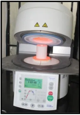
Fig.29 : Heat press furnace
Fig.30 : Induction casting machine
Fig.31 : Sandblaster
Fig.32 : Alloy grinder
Fig.33 : Digital Vernier caliper
Fig.34 : Digital Micrometer
Fig.35 : Digital Ultrasonic cleaner
Fig.36 : Light curing unit
Fig.37 : Spectrophotometer CM 3600 d
Fig.38 : Parts of metallic mold
Fig.39 : Schematic diagram of metallic mold
Fig.40 : Metallic mold in hand press machine
Fig.42 Patters for ceramic disc fabrication:a) 1mm b)1.3mm c)1.6mm
Patterns for Ni-Cr metal discs fabrication: d) 2.5mm
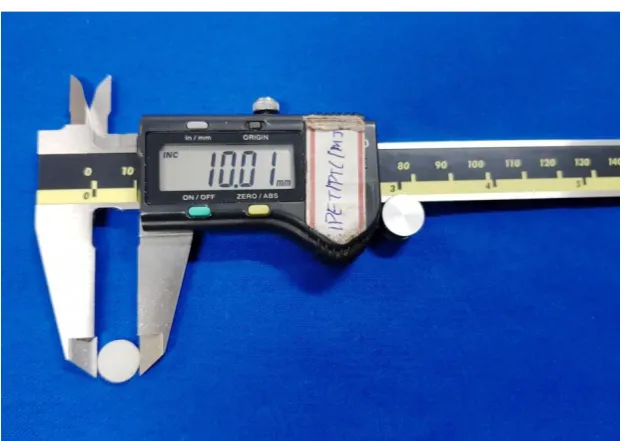
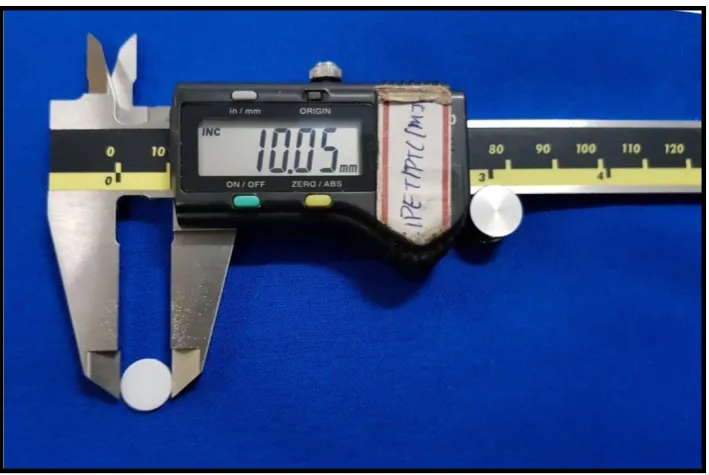
Fig.43 : Verification of diameter of pattern(10mm)
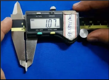
Fig.44 : Verification of thickness of pattern (1mm)
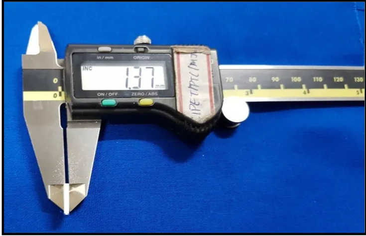
Fig.45 : Verification of thickness of pattern (1.3 mm)
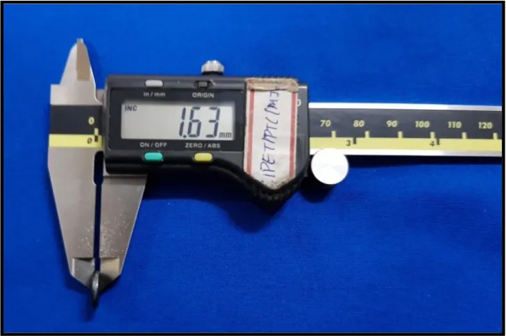
Fig.46 Verification of thickness of pattern (1.6 mm)
Fig.47a : Spruing of pattern
Fig.47b : Attachment of sprued patterns to investment base
Fig.47c : Investing of patterns
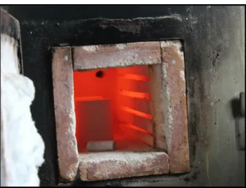
Fig.48 Burn out procedure
Fig.49 : a)Ingot
b) Alox plunger
c) Investment mold
Fig.50 : Placement of LT lithium disilicate ingot with investment tong
Fig.51 : Heat pressing of ingot
Fig.52a : Heat pressed ceramic discs
Fig.52c : Finishing of ceramic disc
Fig.53 : Verification of diameter (10mm)
Fig.54a : Verification of thickness (1mm)
Fig.54b : Grouping of ceramic samples for Group I (1mm)
Fig.55a : Verification of thickness (1.3mm)
Fig.55b : Grouping of ceramic samples for Group II( 1.3mm)
Fig.56a : Verification of thickness (1.6mm)
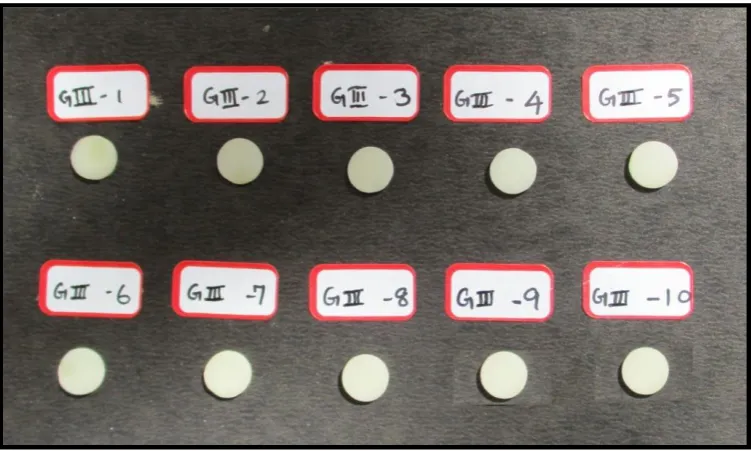
Fig.56b : Grouping of ceramic samples for Group III (1.6mm)
Fig.57 : Verification of pattern for metal disc
Fig.58 : Spruing of patterns
Fig.59a : Vacuum mixing of investment material
Fig.59b : Complete Pouring of investment material into silicone ring
Fig.60 : a) Pre-heating temperature
b) Burnout temperature
Fig.61 : Induction casting procedure
Fig.62b : Sandblasting
Fig.62 c : Separating of the sprue
Fig.63 : Grouping of Ni-Cr metal discs
Fig.64a : Evaluation of colour parameters against white background
Fig.64 b : Placement of ceramic discs against white background
Fig.65a : Embedding metal disc in metal ring using polyvinyl siloxane impression material
Fig.65b : Optical connection of the ceramic disc and Ni-Cr metal disc with distilled water
Fig.66 : Colour measurement of ceramic disc against Ni-Cr metal disc
Fig.67 : Ultrasonic cleaning of ceramic discs
Fig.68a : Application of 10% hydrofluoric acid
Fig.68b : Rinsing with water
Fig.68c : Air drying
Fig.68d : Non-etched and etched ceramic disc
Fig.69 : Metallic template to maintain cement space
Fig.70 : Line diagram of metallic template
Fig.72a : Embedding metal disc in template with putty
Fig.72b : Positioning of spacer at the edge of the metal disc
Fig.72c : Stabilization of the spacer with the upper member of template
Fig.73 : Positioning of 40 µm spacer for all three groups
Fig.74a : Dispensing of resin cement
Fig.74b : Placement of ceramic disc
Fig.74c : Pressure applied to remove excess cement
Fig.75a : Tack curing for 3 sec
Fig.75b : Light polymerization for 40 sec
Fig.76 : Intact spacer ensuring maintenance of cement space
Fig.77 : Storage of discs in air tight dark container
Fig.78 : Group I ceramic discs after cementation
Fig.79 : Group II ceramic discs after cementation
Fig.80 : Group III ceramic discs after cementation
ANNEXURE III
LIST OF GRAPHS
GRAPH NO
TITLE
1 Basic data of L*a*b* values for Group I Lithium disilicate ceramic discs of thickness 1mm against white background 2 Basic data of L*a*b* values for Group II Lithium disilicate
ceramic discs of thickness 1.3 mm against white background
3 Basic data of L*a*b* values for Group III Lithium disilicate ceramic discs of thickness 1.6 mm against white background
4 Basic data of L*a*b* values for Group I Lithium disilicate ceramic discs of thickness 1mm against Ni-Cr metal discs before cementation
5 Basic data of L*a*b* values for Group II Lithium disilicate ceramic discs of thickness 1.3mm against Ni-Cr metal discs before cementation
7 Basic data of L*a*b* values for Group I Lithium disilicate ceramic discs of thickness 1 mm after cementation with Ni-Cr metal discs
8 Basic data of L*a*b* values for Group II Lithium disilicate ceramic discs of thickness 1.3 mm after cementation with Ni-Cr metal discs
9 Basic data of L*a*b* values for Group III Lithium disilicate ceramic discs of thickness 1.6 mm after
cementation with Ni-Cr metal discs
10 Comparative evaluation of the colour difference (∆E) between Group I(1mm),Group II(1.3mm) and Group III (1.6 mm) ceramic discs against white background and Ni-Cr metal discs before cementation
11 Comparative evaluation of the colour difference (∆E) between Group I (1mm), Group II (1.3mm) and Group III (1.6 mm) ceramic discs against white background and Ni-Cr metal discs after cementation
13 Overall comparison of the mean colour difference (∆E) between Group I (1mm), Group II (1.3mm) and Group III (1.6 mm) ceramic discs after cementation
ANNEXURE IV
1
INTRODUCTION
Porcelain - fused to metal restorations have been regarded the gold standard in fixed prosthodontics with 94% success rate over 10 years with good mechanical properties, reasonable aesthetics and an acceptable biological quality required for its service .13,27,35,39,55 However, Porcelain - fused to metal prosthesis have some limitations , which include increased light reflectivity from the opaque porcelain used to mask the metal coping and occasional greying of the gingival tissues resulting in an unattractive appearance.42,50,56 This has led to the introduction of metal free restorations as an alternative to metal-ceramic restorations in daily clinical practice especially for anterior aesthetic restorations.4,9,54,67
Newer metal free crowns are increasingly been used in dental practice
and these crowns are made from different ceramic materials such as leucite-reinforced glass, lithium disilicate, glass-infiltrated alumina and zirconia.37,45,62 The high strength core ceramics such as alumina or zirconia-based ceramics have high opacity and hence require translucent veneering porcelain to achieve adequate shade matching.6 Among the semi-translucent glass-ceramic systems, lithium disilicate has gained popularity for both anterior and posterior crowns because of its superior aesthetics , adequate strength, wear resistance and chemical durability. 11,17,40
2
this structure results in restoration that demonstrates greater strength and durability. 1,2,59 This material has a low refractive index, a characteristic that allows the material to exhibit phenomenal optical properties and optimal esthetics.6,35 Lithium disilicate glass ceramic can be processed using either the lost-wax hot press technique or CAD/CAM version 18. The popularity of Heat pressed ceramics has risen markedly due to its similarity to conventional lost-wax technique and also the equipments required to heat press ceramics is relatively inexpensive. 21,25,33
IPS emax Press Lithium disilicate ceramic presents relatively high flexural strength (350-400MPa) and increased fracture toughness due to its smaller and more homogeneous crystals .10,32 IPS emax Press has been used successfully for monolithic fixed partial dentures even in the posterior area for as long as 8 years .73
3
Several modalities have been employed in attaining an aesthetic restoration. One such method makes use of translucent core ceramic with an opaque cement to mask the substrate, as translucent ceramics have the greatest potential to be affected adversely by the discoloured substrate, but this often produces an undesirable result, as the final shade of the crown is subject to change after cementation. A far more predictable approach is to use a crown with a more opaque core that is less affected by the abutment colour. The layered ceramic systems with more opaque cores are well suited for the treatment of discoloured teeth .24
Shade selection has a positive impact on the patient’s perception of aesthetics and ultimately, the acceptance of their restorations. 4,7,14 Shade matching in clinical practice is obtained by visual assessment and instrument colour analysis .Researchers have shown that visual shade selection is often unreliable and imprecise and have increasingly recommended the use of instrument colour analysis by colorimeters and spectrophotometers.16,28,67 Compared with observations by the human eye or conventional techniques, it was found that spectrophotometers offered a 33% increase in accuracy and a more objective match in 93.3% of cases. 51
4
∆E values are used to distinguish differences in colour: ∆E values < 1 is
considered undetectable by the human eye. Studies have used different ∆E values as clinically acceptable: 3.3 as the perceptibility limit, 5.5 as the acceptability tolerance. 12,13,31
Previous studies have evaluated the masking ability of feldspathic and leucite ceramics, studies evaluating the optical properties of lithium disilicate pressable ceramic and Ni-Cr alloys as anterior indirect restorative materials are very few.
The application of lithium disilicate ceramic material with different translucency blanks for masking different substrate colours are in its early stages and results pertaining to its masking ability are few.
Since the optical properties of all-ceramic restorative material is of paramount consideration with regards to patient’s expectation, the translucency
parameter of these materials needs to be further evaluated .Moreover comparative in vitro studies evaluating the masking ability of lithium disilicate ceramic material of different core thickness over metallic substrates are sparse.
5
OBJECTIVES:
1) To evaluate quantitatively, the L*a*b* values of lithium disilicate ceramic discs of 1mm thickness against white background.
2) To evaluate quantitatively, the L*a*b* values of lithium disilicate ceramic discs of 1.3mm thickness against white background.
3) To evaluate quantitatively, the L*a* b* values of lithium disilicate ceramic discs of 1.6mm thickness against white background.
4) To evaluate quantitatively, the L*a*b* values of lithium disilicate ceramic discs of 1 mm thickness against Ni-Cr metal discs before cementation.
5) To evaluate quantitatively the L*a*b* values of lithium disilicate ceramic discs of 1.3 mm thickness against Ni-Cr metal discs before cementation.
6) To evaluate quantitatively the L*a*b* values of lithium disilicate ceramic discs of 1.6 mm thickness against Ni-Cr metal discs before cementation.
7) To evaluate quantitatively the L*a*b* values of lithium disilicate ceramic discs of 1 mm thickness after cementation with Ni-Cr specimens.
8) To evaluate quantitatively the L*a*b* values of lithium disilicate ceramic discs of 1.3 mm thickness after cementation with Ni-Cr metal discs.
6
10) To evaluate the colour difference (∆E) of 1mm, 1.3mm and 1.6mm Lithium disilicate ceramic discs against white background and Ni-Cr metal discs before cementation.
11) To evaluate the colour difference (∆E) of 1mm, 1.3mm and 1.6mm Lithium disilicate ceramic discs against white background and Ni-Cr metal discs after cementation.
12) To comparatively evaluate the mean colour difference value (∆E) between 1mm, 1.3mm and 1.6mm lithium disilicate ceramic discs before cementation respectively.
13) To comparatively evaluate the mean colour difference value (∆E) between 1mm, 1.3mm and 1.6mm lithium disilicate ceramic discs after cementation respectively.
7
REVIEW OF LITERATURE
Rosenblum et al (1997)55 explains about the evolution of ceramic restorations from porcelain fused to metal restorations and their drawbacks which prompted the development of new all-ceramic systems. The author summarises on the different types of all ceramic materials currently available, from the conventional powder slurry ceramics, castable ceramic, machinable pressable and infiltrated ceramics. The author compares the physical properties of the different systems and suggests the use of stronger materials in stress bearing areas and softer materials in situations in which tooth abrasion may be critical (lingual surfaces of upper anterior teeth).
Vichi et al (2000)69 evaluated the influence of the colour of two commercially available non-metallic opaque posts (carbon fiber and zirconia) and an experimental aesthetic post with white yellow ,brown shade luting cements of thickness 0.1 and 0.2mm on the aesthetics of IPS Empress ceramic restorations. The study concluded that 2mm thick IPS Empress restoration was not affected by discoloured substrates but when the thickness reduced to 1.5 mm there was a need to evaluate the substrate.
8
greater translucency of the material, concerned with the posts and cores at the standard crown thickness used, the matte-finished gold alloy had the lowest luminance and ceramized metal and polished gold alloy posts and cores had intermediate values of luminance that were very similar to each other.
Heffernan et al (2002)35evaluated the Relative translucency of six all-ceramic core materials at clinically appropriate thicknesses .These cores can be veneered with porcelain in clinical practice to improve the esthetics. The thickness of a core material affects its strength and optical properties .On the basis of translucency, In-Ceram Spinell may be recommended for matching adjacent, highly translucent natural teeth .For moderately translucent
teeth, Empress, Procera and Empress 2 were feasible restorative materials. In-Ceram Alumina may be used for moderately opaque teeth; for opaque teeth,
there may be no difference in the translucency of In-Ceram Zirconia and a metal-ceramic restoration
9
gold-alloy, the dentin ceramic must be more than 1.6 mm thick; in cases where this thickness cannot be attained, it is effective to make a post using tooth-coloured material, such as a porcelain veneered cast post.
Dozic et al (2003)29 evaluated quantitatively, the effect of different thickness ratios of opaque porcelain (OP) and translucent porcelain (TP) layers on the overall shade of all-ceramic specimens. The author explained that even small changes in OP/TP thickness ratio can perceivably influence the final shade of the layered specimens (∆E >1). Redness a* and yellowness b*
increased with the thickness of OP for all shades. Redness a* (p <0 .01) for all
shades) correlated more strongly with thickness than yellowness b* with (p < 0.01) for A1 and A3; (p < 0.05 )for A2. The lightness (L*) was
shade dependent. A thickness of 0.70 mm of the Core material tested is sufficient to mask the influence of the background colour on the final shade of the layered specimens.
10
Kelly et al (2004) 39explains the three main divisions to the spectrum of dental ceramics: (1) predominantly glassy materials, (2) particle-filled glasses, and (3) polycrystalline ceramics .All-ceramic systems can provide a better esthetic result than metal-ceramics because a wide range of translucency-opacity can be achieved with commercially available ceramic systems. Other advantages of all-ceramic restorations over metal ceramics include better emergence profile, better soft tissue health leaving the margin supragingival or at the gingival margin enabling preservation of biological width.
Raptis et al (2006)54 summarizes on the history of clinical success of porcelain fused metal restorations with combined good aesthetic results and inherent strength. The author also evaluates on its limitations and alternative methods of fabrication of restoration thereby improving shade replication of restoration. The options include metal-ceramic crowns with castings 2 mm short of the shoulder preparation and 360-degree porcelain margins permitted light transmission through gingival portion of tooth. IPS Empress and In-Ceram Spinell all-ceramic restorations demonstrated equally good light transmission properties. In-Ceram Spinell presented better reflection and refraction characteristics, as well as colour matching properties, compared to restoration with a 2-mm short coping and 360-degree porcelain margin.
11
indirect composite resins ,porcelain laminates ,all-ceramic crowns and all- ceramic fixed partial dentures. The author explains on the advantages of all-ceramic restorations over metal-ceramic restorations and the importance the ceramic coping design on the long term success of restoration .The author also summarises the importance of toughened ceramics and its indication in stress bearing area. With innovations in biocompatibility, strength, marginal adaptation and optical qualities of dental materials, the prognosis of esthetic restorations appears to depend predominantly on choice of material, precise technique and patient selection.
Shimada et al (2006)60 evaluated the influence of composite build-up material , a gold alloy and a silver palladium alloy as abutment materials on the colour of IPS Empress 2 ceramic coping with different thicknesses 0.8, 1.0 ,1.2 ,1.4 ,1.6, 1.8 ,and 2.0 mm. For the IPS Empress 2 ceramic coping, minimum thickness of 0.8 mm recommended by the manufacturer is appropriate .Ceramic copings of Empress 2 of 1.6 mm thickness or more , prevented the abutment materials to exert any clinically unacceptable colour influence
12
efficiency of Empress 2 was lower than Procera cores due to the reduced crystal volumes. The clinical application of these two ceramics as a veneer material may still be limited when applied over intense tooth discolouration because neither can fully mask the colour of a black background.
Conrad et al (2007)17 reviews the current literature on all-ceramic materials and systems, with regards to survival, marginal and internal fit, material properties, cementation and bonding, colour and esthetics and provides clinical recommendations for their use. The review demonstrates the multiple all-ceramic materials and systems currently available for clinical use and suggest that there is not a single universal material or system for all clinical situations. The successful application is dependent upon the clinician’s
ability to match the materials, manufacturing techniques and cementation or bonding procedures, with the individual clinical situation.
Douglas et al (2007)28 studied about the acceptability and perceptibility tolerances for shade mismatch using spectrophotometric analysis. Tolerances for acceptability were significantly higher than tolerances for perceptibility of shade mismatch between 2 artificial acrylic resin teeth. The author revealed that the Mean colour perceptibility tolerance for which
50% of the dentist observers could perceive a colour difference (50/50 perceptibility) was 2.6 ∆E units. The predicted colour difference at
13
Griggs et al (2007)33 explains about the recent advances in materials for all-ceramic systems restoration that mimic the appearance of the natural teeth .He summarises the method of ceramic fabrication such as powder condensation, slip casting, heat pressing and CAD-CAM manufacturing . Interpretation of variety of invitro studies pertaining to mechanical reliability, marginal adaptation or bonding to resin cements, various processing protocols and survival probabilities of all-ceramic veneers ,inlays , onlays ,crowns and fixed partial dentures are discussed in this review.
Della Bona et al(2008)24 explains a comprehensive review about the clinical evidence for the treatment of natural teeth using all-ceramic restorations .The study suggested the use of any all-ceramic system for veneers, intra-coronal restorations and complete-coverage restorations for
single-rooted anterior teeth while Molar restorations include those made of
alumina and increasingly, zirconia and bonded lithium disilicate. Reasonable
evidence has shown the effectiveness of anterior three-unit fixed partial
dentures made from lithium disilicate, alumina and zirconia. For three-unit
restorations in posterior regions, expert consensus suggests that only
zirconia-based systems are indicated.
14
colour of IPS-Empress and IPS-Empress 2 systems. The study concluded that when the substrate presents a colour very similar to the ceramic, the thickness of 1.5mm can be utilized for any of the systems tested and if there are metallic posts and cores present, it becomes necessary to create enough space to mask the substrate and to select a restorative system that presents a ceramic substructure.
Chu et al (2010)16 reviewed the current status of hand held systems for tooth colour matching. The study revealed that Spectrophotometers, colorimeters and imaging systems are useful and relevant tools for tooth colour measurement, analysis and for quality control of colour reproduction. Different measurement devices either measure the complete tooth surface providing a ‘‘colour map’’ or an ‘‘average’’ colour of the limited area
[3–5 mm] on the tooth surface. These instruments are considered to be useful tools in colour analysis for direct or indirect restorations, communication for indirect restorations, reproduction and verification of shade. Whenever possible, both instrumental and visual colour matching method should be used, as they complement each other and can lead towards predictable esthetic outcome.
15
enumerates on the broad classification of dental ceramics into metal-ceramic and all-ceramic systems, its composition and their different fabrication techniques. The author explains the common important characteristics of all-ceramic systems, such as the proportion of glassy phase and amount of porosity and their influence on optical and mechanical properties.
Shao et al (2010)58 evaluated the effect of 18-8 nichrome alloy, and Bio Herador N bio-type noble metal-ceramic alloy and A2 colour photo-curing compound resin materials colour on the chromatic value of In-Ceram zirconia core, Cercon base zirconia core, and Cercon base colour zirconia core at thickness 0.5±0.01mm and Empress II at 0.8±0.01mm .The colour difference of Empress II samples was more than 1.5 among the background colour groups, while that of Zirconia was less than 1.5. The influence of background colour on the Empress II dentin was visible, such that it can be used on a tooth colour post. The influence of background colour was invisible for the three kinds of Zirconia core materia1s, exhibiting excellent masking abilities and could be used on any colour background.
16
clinically influence the overall selected colour of 0.5 mm ceramic laminate veneers, regardless of the ceramic material shade.
Chaiyabutr et al (2011) 10 evaluated the resulting optical colour of a CAD/CAM glass-ceramic lithium disilicate-reinforced crown due to the effect of tooth abutment colour, cement colour and ceramic thickness of 1mm,1.5mm, 2mm and 2.5mm. The study revealed that a dark-coloured abutment tooth demonstrated the greatest ΔE values compared to other variables tested. For dark-coloured abutment teeth, crowns with a ceramic thickness of 1.0 mm cemented using either translucent cement or opaque cement and crowns with a ceramic thickness of 1.5 mm cemented with translucent cement resulted in within a clinically unacceptable range in terms of colour change (ΔE>3.7).
Cubas et al (2011)20 assessed the influence of varying ceramic thicknesses and luting agents on colour variation of Vitadur- Alpha ,Noritake Super Porcelain EX-3 , Vision-Esthetic ,IPS Classic ,All Ceram and Vintage Halo veneering ceramics, with Resin composite discs (Z-250, shade C4) used as bases to simulate a chromatic background. The study revealed that 2-mm thickness with opaque cement presented the strongest masking ability of a dark coloured background when compared to a non- opaque luting agent and the other thicknesses tested.
17
as fabrication methods for clinical restorations, fit of ceramic restorations, clinical failure mechanisms of all-ceramic prostheses, chemical and thermal strengthening of dental ceramics, intraoral porcelain repair and the criteria for selection of various ceramics available. It is found that strong scientific and collaborative foundations exist for the continued.
Kilinc et al (2011) 41 evaluated the resin cement colour stability and its effect on the final shade of the all-ceramics. Adhesive resin cements may undergo internal discolouration, which may be seen through , affecting the appearance of translucent all-ceramic restorations. Light cure resin cements are recommended mostly for anterior restorations due to better colour stability. The ceramics luted with Dual Cured resin cement groups showed findings of more colour change because of the oxidation of reactive groups in amine accelerators and inhibitors affecting the aesthetics of final restoration margins if directly exposed.
18
long-term success of Porcelain laminate veneers restorations .Colour changes in restorative materials induced by UV irradiation have been related to chemical alterations in the initiator system, activators and the resin. The author also concluded that the discolouration observed after the ageing process was within a clinically acceptable level.
Vichi et al (2011)70 explains about the difficulty in shade match due to varied optical properties of tooth colour. Colour match between natural dentition and restoration or prosthesis is a complex process which consists of two specific procedures: colour selection and colour reproduction .The author explains the advantages of spectrophotometer over visual assessment. Colour selection has advanced through the development of new shade guides and electronic shade taking devices, although visual assessment has still not been entirely replaced by electronic instrumentation.
Aiqahtani et al (2012)1 evaluated the colour difference (ΔE) of three different ceramic materials (IPS Empress Esthetic Press, IPS Empress e.max Press, IPS Empress ZirPress from standard (on substrate without cement) and when different shades of light-polymerizing Translucent, White Opaque, B0.5, A1, and A3 of RelyX™ Veneer were used under two different thicknesses (0.5 mm and 0.7 mm) . ΔE was higher for leucite reinforced glass-ceramic
(IPS Empress Esthetic) followed by fluorapatite glass-ceramic (IPS Empress ZirPress) and lowest mean ΔE values were for lithium disilicate glass-ceramic.
19
0.5 mm to 0.7 mm. It was observed that the White Opaque had significantly increased ΔE values when compared with (TR, B 0.5, A1, and A3)
Shono et al (2012)60 evaluated the contrast ratio (CR) and masking ability of IPS e.max Press, VitaVM7 and Nobel Rondo Press Alumina(NRPA) veneering ceramics at 1mm/1.5mm thicknesses by measuring the colour differences over white and black backgrounds . NRPA demonstrated the least masking ability among the three ceramics tested. IPS emax and VM7 had similar masking abilities, but IPS emax exhibited higher CR percentages than VM7. All the materials tested in this study were not capable of completely masking the underlying black background, although the masking ability improved when the thickness was increased from1.0 to 1.5 mm.
Zhou et al (2012)73 evaluated the ability to mask a dark background such as a dark tooth or core buildup material of IPS e.max all-ceramics system of HO series. The colour differences of ceramic disks with the thicknesses of 0.6mm and 0.8mm were undistinguishable by the human eyes resulting in esthetic restorations. While the thickness of 0.4mm and 1.0mm ones were distinguishable implied to a reluctant outcome. Specimens with the thickness of 1.0mm could prevent metal substrate colour transmitting through the cylindrical specimens, but resulted in an unesthetic outcome.
20
White opaque (Nexus) cement at 100- µm cement-film thickness resulted in the best colour match with colour difference below the clinical perceptible threshold (∆E< 2.6) relative to the target block. Increasing the cement
thickness above 100 µm did not improve the shade match. Nexus3 white opaque at all thicknesses and Multilink white opaque at 50 µm resulted in the best shade matches
Chen et al(2015)12 evaluated the effect of Variolink Veneer, shades LV-3, LV-2, MV, HV + 2, HV + 3; Panavia F, shades light and brown; and RelyX TM Veneer, shades WO, TR, A3 resin cement on the final colour of IPS emax Press, LT A3 shade ceramic veneer .A spectrophotometer (VITA
Easyshade) was used to measure the colour parameters (CIE L*a*b* values).The study revealed that different shades of resin cement
produced obvious effects on the final colour of ceramic veneers, the resin cement shades HV + 3 and WO can increase the brightness resulting in ∆E
values more than 3.3 and reduce the chroma of ceramic veneers, whereas the resin cement shades LV-3 and brown tend to increase the chroma.
21
the range of the clinically acceptable colour difference (ΔE ≤3.3), thus all the
groups could mask the C4 background including group 1 with only 0.8 mm thickness. The author concluded that the minimum thickness of a multilayer porcelain restoration (IPS e.max Press) required for masking severe tooth discolouration was 0.8 mm including a 0.4 mm core and 0.4 mm veneer
Dede et al (2016)23 evaluated the effects of A1, A2, A3, B2, C2 composite resin foundation and shades of Translucent (Tr), Universal (Un=A2), and white-opaque (Wo) resin cement materials on the colour of medium-opacity and high-translucency lithium disilicate ceramics . The author revealed that when translucent and universal cement shades were used, the core shade did not affect the final colour of the ceramics. White opaque cement caused clinically unacceptable colour changes in both ceramics on all shades of CRFs except the C2 CRF and when high translucency ceramic was used on the A2 CRF. These changes were clinically acceptable, but perceptible.
22
acceptable range and hence the clinical implication of Group III ‑ HO may be limited to be applied over intensely stained tooth.
Perroni et al(2016)52 evaluated the influence of different shades of flowable resin composite A1, A2, B1, white opaque or translucent on the
final shade of monolithic (enamel E1.0 or dentin D1.0) and bilayer (E0.5
D0.5) feldspathic porcelain over A2 and B1simulated dental substrate .
Porcelain veneer E1.0 groups were the most translucent, while the pairs veneer
with luting agent WO showed the lowest translucency, and A1,A2,B1, and IL
yielded little to no differences in translucency of the pairs. The overall best
shade matching with A2 substrate was observed for D1.0 veneer and WO
luting agent.
Pires et al (2016)53 evaluated the effect of the substrate, cement, type, and thickness of the ceramic on the resulting colour of IPS e.max Press LT (low translucency) and HO (high opacity) at thicknesses (1.5 and 2 mm) .The study revealed that the substrate colour, type and thicknesses of ceramic and the presence of cement significantly influenced the resulting optical colour with the ∆E values of cemented HO ceramics lower than those of the LT
ceramic. On a metallic alloy substrate, the ceramic crown should be fabricated only with high opacity ceramic. The translucent ceramic is indicated for dentin or resin substrate.
23
thickness (0.7,1,1.5 and 2mm) and bilayer IPS e.max Zir CAD ceramic structures(0.5 mm thick zirconia framework with CAD-CAM lithium disilicate veneer) against a typical dental shade substrate (A2) and discoloured backgrounds (shade C4, coppery, and silvery). The study revealed that as thickness of lithium disilicate ceramic reduces, its translucency parameter and colour difference increased. Monolithic CAD –CAM lithium disilicate masked tooth coloured substrate better than metallic backgrounds. Bilayer ceramic structures, improved masking over all evaluated substrates.
Leevailoj et al (2017)43 examined the influence of material type, thickness, and substrate colour on the masking ability of IPS emax lithium disilicate glass ceramic ,high-translucent zirconia and high-translucent zirconia with liner ceramics over white ,black ,metal and resin composite shades A2 ,A3 and C 4. Both contrast ratio and masking ability increase as thickness increased. A darker substrate colour reduced the masking ability of ceramics when compared with a lighter- colour substrate. For improved masking ability, high opaque IPS e.max Press is recommended over Lava Plus and Lava Plus/Liner for the masking of dark substrates.
Tabatabaian et al (2017)65 studied the masking ability of zirconia
copings against different composite shades ,A3 shade zirconia, Nickel –Chromium alloy, non –precious gold coloured alloy, amalgam ,black
24
difference for black and white backgrounds than for tooth–coloured and metal alloy backgrounds .The author concluded that the best method of masking the background colour was to use zirconia coping with a proper thickness. To achieve ideal masking, the minimum thickness of a zirconia coping should be 0.4 mm for A1 ,A3.5 shade composite resin, A3 shade zirconia and nonprecious gold-coloured alloy, 0.6 mm for amalgam, and 0.8 mm for nickel-chromium alloy.
25
MATERIALS AND METHODS
This in vitro study was conducted to comparatively evaluate, the masking ability of lithium disilicate ceramic with different core thickness on the shade match of indirect restorations over metallic substrate.
The following materials, instruments and equipments were used in the present study:
Materials used:
Acetyl sheet of thickness - 1mm/1.3mm/1.6mm/2.5mm (Plastic house,
Paris,chennai) (Fig.1)
Sprue wax 3mm diameter (Bego, Germany) (Fig.2)
Surfactant spray (Aurofilm, BEGO, Germany ) (Fig.3)
Phosphate bonded investment material (Bellavest SH, Bego, Germany)
(Fig.4)
Colloidal silica (Begosol, BEGO, Germany) (Fig.5) Distilled water (Merck & Co., Mumbai India) (Fig.6)
Low translucency Lithium disilicate pressable ingots (Ivoclar vivadent,
USA) (Fig.7)
Invex liquid (Ivoclar vivadent, USA) (Fig.8)
Silicon carbide emery papers (3M India Ltd., Bangalore, India) (Fig.9)
Nickel Chromium casting alloy pellets (Bellabond plus BEGO, Germany)
26
Aluminium oxide 50 µm (Korox, Alpha bond, Australia) (Fig.11)
White background (A4 Sheet-JK copier) (Fig.12)
Polyvinylsiloxane impression material (Variotime putty, Kulzer, Germany)
(Fig.13)
Hydrofluoric acid 10% (IPS Ceramic etching gel, Ivoclar vivadent, USA)
(Fig.14)
Brass sheet 40µm (Fig.15)
Resin luting cement (Maxcem Elite, Kerr, USA) (Fig.16)
Instruments used:
PK Thomas instruments (Fig.17)
Silicon Investment ring system for emax press (Ivoclar vivadent, USA)
(Fig.18)
Alox plunger (Ivoclar vivadent, USA) (Fig.19)
Fine diamond disc (Dentorium, New York, U.S.A) (Fig.20)
Crucible former and Silicone casting rings for metal casting (Siliring, Delta
labs, Chennai, India) (Fig.21)
Metal separating disc and mandrel (Dentorium, New York, U.S.A)
(Fig.22a & b)
Tungsten carbide bur (Edenta, Switzerland) (Fig.22c)
Metal rings (Fig.23)
27 Equipments Used:
Hand Press machine (Indian Tools Corp) (Fig.26)
Vacuum mixer (The Continental, Whip Mix, Kentucky ,USA) (Fig.27)
Burnout furnace( Technico laboratory Products Pvt. Ltd.) (Fig.28)
Heat press furnace -Programat EP 3000 (Ivoclar vivadent, USA) (Fig.29) Induction casting machine (Fornax GEU, BEGO, GERMANY) (Fig.30)
Sandblaster (Delta labs, Chennai, India) (Fig.31)
Alloy grinder (Demco, California, U.S.A.) (Fig.32)
Digital Vernier caliper (Mitutoyo, Japan) (Fig.33) Digital Micrometer (Mitutoyo, Japan) (Fig.34)
Digital Ultrasonic cleaner (Beijing Ultrasonic Co., China) (Fig.35) Light curing unit (3M ESPE) (Fig.36)
Spectrophotometer (CM 3600d) (Fig. 37)
Description of Spectrophotometer: (Fig.37)
28
Diffused Light from the pulsed xenon lamps, reflected from the inner surface of the integrating sphere illuminates the specimen uniformly. The light reflected from the surface of specimen at angle of 8◦ is then received by the specimen measuring optical system and the diffused light in the integrating chamber received by the illumination-monitoring optical fiber are guided to the sensor. In the sensor, the light in the wavelength range of 360-740 nm is divided into 10 nm-pitch components and is projected onto the sensory array sections, which convert the light into proportional current and direct the current to the analog processing circuit. The spectrophotometer is connected
Model CM3600d
Illumination/viewing system
Reflectance: d/8(diffused illumination, 8-degree viewing)
Light-receiving element Silicone photo diode array(dual 40 elements)
Spectral separation device Diffraction grating Wavelength range 360nm-740nm Wavelength pitch 10nm
Reflectance range 0to 200%; resolution 0.01% Light source Pulsed xenon lamps(x4) Measurement time Approx 1.5 seconds
29
to a computer which has a software installed JAYPAK 4808 to analyse the data.
30
METHODOLOGY
This in vitro study was conducted to comparatively evaluate, the masking ability of lithium disilicate ceramic with different core thickness on the shade match of indirect restorations over metallic substrate.
The methodology adopted in the present study is described under the following sections:
I Fabrication of custom metallic mold.
II Fabrication of plastic patterns for lithium disilicate ceramic discs and Ni-Cr metal discs:
A. Fabrication of plastic patterns for lithium disilicate ceramic discs.
B. Fabrication of plastic patterns for Ni-Cr metal discs. III Fabrication of Heat pressed ceramic discs:
A. Investing of patterns. B. Heat pressing.
IV Grouping of lithium disilicate ceramic discs. V Fabrication of Ni-Cr metal discs:
A. Investing and casting of plastic patterns.
31
VII Evaluation of colour measurements of Lithium disilicate ceramic discs against white background.
VIII Evaluation of colour measurements of Lithium disilicate ceramic discs against Ni-Cr metal discs before cementation.
IX Cementation of Lithium disilicate ceramic discs to Ni-Cr metal discs using resin cement.
A. Surface preparationof lithium disilicate ceramic discs.
B. Fabrication of a metallic template to standardize the cement thickness at 40 microns.
C. Cementation of ceramic discs to Ni-Cr metal disc. D. Light polymerization.
E. Storage of cemented lithium disilicate ceramic disc-Ni-Cr metal disc in
distilled water.
X Evaluation of colour measurements of lithium disilicate ceramic discs against Ni-Cr metal discs after cementation.
XI Measurement of colour difference (∆E). XII Data tabulation and statistical analysis
I) Fabrication of custom metallic mold: (Fig.38-39)
32
10mm in diameter and an upper counterpart (Fig.39B). The upper counter part consists of 4 pivots and a plunger. The pivots facilitate the plunger to penetrate the orifice situated in the base when held in the hand press machine (Indian Tools Corp) (Fig.26).
II. Fabrication of plastic patterns for lithium disilicate ceramic discs and Ni-Cr metal discs: (Fig: 40-42)
A. Fabrication of plastic patterns for lithium disilicate ceramic discs: (Fig: 40-42)
The acetyl plastic sheets of thickness 1mm/1.3mm/1.6mm (Plastic house,
Paris) (Fig.1) were selected to fabricate plastic patterns for Lithium disilicate ceramic
discs. The acetyl plastic sheet was placed between the base and the upper counter part
of the metallic mold, when the entire assembly was placed on to the hand press
machine (Fig.40). On activation, the plunger penetrated the acetyl plastic sheet and
produced plastic disc patterns (Fig.41). Thus, 10 discs for each thickness were
obtained making a total of 30 plastic disc patterns, for the fabrication of the Lithium
disilicate ceramic discs (Fig.42 a, b, c).
B. Fabrication of plastic patterns for Ni-Cr metal discs : (Fig: 40-42)
The acetyl plastic sheet of 2.5mm thickness (Plastic house, Paris) (Fig.1) were selected to fabricate plastic patterns for Ni-Cr metal discs. The acetyl
33
and produced plastic disc patterns (Fig.41). Thus 30 plastic disc patterns were obtained for the fabrication of metal substrate (Fig.42d).
III. Fabrication of Heat pressed ceramic discs :( Fig. 43-56)
A) Investing of patterns: (Fig.43-48)
The dimensions of the plastic patterns for fabrication of ceramic discs were verified with the help of digital vernier caliper (Mitutoyo, Japan) to 10mm diameter and thickness 1mm/1.3mm/1.6mm (Fig.33, 43-46). A sprue wax of 3mm (Bego, Germany) (Fig .2) was attached on the edge of the plastic disc patterns at an angle of 45◦ to the investment ring base (Fig.47a, 47b). The patterns were widely spread at a distance of 3mm. The sprued patterns were coated with surfactant spray (Aurofilm, BEGO, Germany) (Fig.3) to improve the wetting of the pattern.
34 B) Heat pressing :( Fig: 49-52)
On completion of the preheating cycle, the investment mold was removed from the burnout furnace (Fig.28) and the cold Low translucency Lithium disilicate Pressable ingot (Ivoclar vivadent, USA) (Fig.7) was positioned into the hot investment mold (Fig.49) with the help of IPS e.max Alox plunger (Fig.19, 50).The investment mold is placed in the heat press furnace (Fig.29) and programmed to obtain heat pressed ceramic discs (Fig.51). Thus the patterns were invested, heated and pressed (Fig.52a) in accordance with the manufacturer’s instructions. Investment mold is bench
cooled and divested with glass beads. The reaction layer formed on the ceramic surface was ultrasonically cleaned in Invex liquid (Ivoclar Vivadent, USA) (Fig.8) for 10 minutes, which contains <1% hydrofluoric acid followed by complete removal of the reaction layer from the contact surfaces using Al2O3 at 1–2 bar pressure (15–30 psi). The ceramic discs were separated using a fine diamond disc (Dentorium, New York, U.S.A) (Fig.20, 52b). Finishing of ceramic discs was done using silicon carbide sheets of different grits (3M India Ltd., Bangalore, India) (Fig.9 &52c).The thickness of all the finished ceramic discs were verified with a digital vernier caliper.
IV. Grouping of lithium disilicate ceramic discs: (Fig: 53-56)
35
Group I: 1mm thickness of Lithium disilicate discs (n=10). (Fig.54a, 54b)
Group II: 1.3mm thickness of Lithium disilicate discs (n=10). (Fig.55a, 55b)
Group III: 1.6mm thickness of Lithium disilicate discs (n=10). (Fig.56a, 56b)
V. Fabrication of Ni-Cr metal discs: (Fig.57-62)
A) Investing and casting of plastic patterns: (Fig: 57-61)
The dimensions of the plastic patterns for fabrication of metal discs were verified to 10mm diameter and thickness of 2.5mm with the help of a digital vernier caliper. (Fig.57)
The plastic patterns were attached with a preformed wax sprue of 3mm diameter (Fig.58). The patterns were evenly spread at an angle of 45-degree to the runner bar for the uninterrupted flow of the molten metal, which at its apex was attached to the crucible former. The sprued patterns were coated with surfactant spray to improve the wetting of the pattern.
36
removed. The set investment was placed in a burnout furnace (Technico, Ind Products, Chennai) in a position with the crucible end contacting the floor for escape of melted wax. The wax patterns were subjected to pre-heating technique in the burnout furnace at temperature of 450◦C for 30 minutes (Fig.60a). Then the investment mold was continuously heated to 950◦C at the rate of 8C◦/min in the burnout furnace (Fig.60b). The investment mold was kept in the induction casting machine (Fornax GEU, BEGO, GERMANY) (Fig.30) (Fig.61a) and aligned such that the sprue hole was approximating the ceramic crucible. Three Ni-Cr casting alloy pellets (Bellabond plus BEGO, Germany) (Fig.10) were placed in the crucible and the counterweight was balanced. The casting temperature of the alloy was adjusted to 1500 ◦C. Once the alloy had melted, the lever was released to cast the metal into the mold. In this manner thirty metal substructures were obtained (Fig.61b).
B) Finishing and surface treatment of Ni-Cr metal discs by sandblasting: (Fig.62)
After bench cooling, the castings were divested (Fig.62a) and the
residual surface investments were removed by means of a sandblaster (Delta labs, Chennai, India) (Fig.31) using 50µm aluminium oxide (Korox,
Alpha bond, Australia) (Fig.11,62b)
37
cement, was cleaned with pressurized steam for removal of any surface contaminants using a steam cleaner. The average thickness of the metal was adjusted to 2.5mm. The surface was air abraded with 50 µm aluminium oxide at 75 psi pressure.
VI. Grouping of Ni-Cr metal discs :(Fig . 63)
Thirty Ni-Cr metal substructures were obtained. 10 metal discs were randomly assigned to each group of lithium disilicate ceramic. (Fig.63)
VII. Evaluation of colour measurements of lithium disilicate ceramic discs against a white background: (Fig.64a, 64 b)
The specimens were placed against a standard white background (A4 Sheet-JK copier) (Fig.12 & 64a) and the colour parameters (L*a*b) of the
specimens were determined with CM-3600d spectrophotometer (Fig.37) in wavelength 360-740 nm. The L*, a*, b* parameters were measured according to Commision Internationale de I’Eclairage (CIE) using D 65 illuminant and
observer function at 10◦. (Fig.64b)
VIII. Evaluation of colour measurements of lithium disilicate ceramic
discs against Ni-Cr metal discs before cementation: (Fig: 65-66)
38
distilled water with refractive index of 1.7 was placed between the discs when they were brought together so that a good optical contact is possible during the spectrophotometric measurement. (Fig.65b).The optically connected ceramic disc and metal disc were embedded within silicone putty in a metal ring to avoid the influence of external light. The colour coordinates (L*a*b*) were determined with CM-3600d spectrophotometer in wavelength 360-740 nm. The L*, a*, b* parameters were measured according to Commision Internationale de I’Eclairage (CIE) using D 65 Illuminant and observer
function at 10◦ (Fig.66).
IX. Cementation of lithium disilicate ceramic discs to Ni-Cr metal discs using resin cement: (Fig.67-77)
A) Surface preparationof lithium disilicate ceramic discs: (Fig.67, 68)
The ceramic discs were placed in an ultrasonic cleaner( Beijing
39
B) Fabrication of a metallic template to standardize the cement thickness at 40 microns: (Fig: 69,70)
A custom-made metallic template was used to ensure the space required for the luting cement. It consists of a base engaged to an upper counter (Fig.69, 70).The base was provided with slots for engaging the spacer.
C) Cementation of ceramic discs to Ni-Cr metal discs: (Fig.71-74)
A brass sheet of 40 µm thick (Fig.15) verified using digital micrometer (Mitutoyo, Japan) (Fig.34) was used as a spacer (Fig.71). The metal disc was stabilised within the orifice in the base of the template (Fig.72). The brass sheet was held in position by the space created at the three corners of the base engaging the upper counter (Fig.73). The resin luting cement (Maxcem Elite, Kerr, USA) (Fig.16) was delivered using automix system (Fig.74a) on to the sandblasted Ni-Cr metal disc substrate and over this the ceramic disc was placed (Fig.74b) and held with finger pressure to maintain the cement thickness at 40µm (Fig.74c).
D) Light polymerization: (Fig.75, 76)
40
of the luting space was verified on removing the assembly from the template (Fig.76).
E) Storage of cemented lithium disilicate ceramic disc-Ni-Cr metal disc in distilled water: (Fig.77)
The cemented lithium disilicate disc-Ni-Cr metal disc assembly was then suspended in distilled water for 24 hrs in a closed air tight dark container (Fig.25) to allow complete polymerization before the commencement of spectrophotometric analysis (Fig.77). The same procedure was followed for all the 30 test specimens.
X. Evaluation of colour measurements of lithium disilicate ceramic discs against Ni-Cr metal discs after cementation: (Fig: 78-81)
Following complete polymerization, the cemented ceramic specimen was embedded within putty in a metal ring, to avoid the influence of external light. The colour parameters of the Lithium disilicate discs after cementation (Fig: 78-81) was measured with CM-3600d spectrophotometer in wavelength 360-740 nm. The L*, a*, b* parameters were measured according to
Commision Internationale de I’Eclairage (CIE) using D 65 Illuminant and
observer function at 10◦ .
XI. Measurement of colour difference:
41
object’s colour, the spectral distribution of light reflected from the object must be known and that spectral reflectance must be averaged by three weighing functions called the colour matching functions and they characterise the colour matching properties of an average observer with normal colour vision, known as the 1931 CIE standard observer. They are weighed by relative spectral power distribution of CIE standard illuminants. The resultants Tristimulus X, Y, Z are then the standard response of the eye to the red, green and blue stimuli from the object.
Knowing the tristimulus values for a particular specimen is beneficial in terms of labelling its colour. In discussing the colour difference between objects, CIELAB system can be employed. The magnitude and direction or shift of the difference between two colour stimuli can be identified.
L* defines lightness,
a* denotes the red/green value b* denotes the yellow/blue value.
The colours of each opponent pair are indicated by the positive and negative values of a* and b*.
Calculation of (CIELAB) L* , a* and b*:
42 L*=116 (Y/Yn) 1/3-16
a*=500[(X/Xn)1/3-(Y/Yn) 1/3]
b*=200[(Y/Yn)1/3-(Z/Zn)1/3]
where Xn, Yn and Zn are the tristimulus values of reference white. For D 65 illumination at 2◦ observer Xn =95.01,Yn=100.0 and , Zn =108.82.
In the CIELAB system, the total colour difference ΔΕ combines the difference of three independent variables such as:
The lightness, represented in the L *axis
Minimum value means a shift to darker (black)
Maximum value means a shift towards lighter (white)
Along the a* axis, value in the positive direction depicts a shift toward red, value in the negative direction depicts a shift toward green.
Along the b* axis, value in the positive direction depicts a shift toward yellow, value in negative direction depicts a shift toward blue.
At the centre of this plane it is neutral or gray.
These formulas, as well as those for determining as perceiving colour difference between the two objects (∆E) as follows
43 ∆L- difference in lightness
∆a -difference in a coordinates
∆b -difference in b coordinates
∆E –total colour difference
The expressions for these colour differences are ΔL* Δa* Δb* (Δ symbolizes “delta,” which indicates difference).
CM-3600d spectrophotometer was used to analyse the colour difference. The system was connected to the computer. The target mask was selected based on the specimen and application. The system was calibrated with a white calibration plate and zero calibration plate. The specimen was held against a white background with the help of a sample holder and the L* a* b* values were displayed in the system. Then following the cementation of the metal discs to the ceramic discs the colour coordinates were measured by placing the sample within a putty mold to avoid the influence of external light. The colour difference was measured by the following formula
ΔE = [(ΔL) 2 + (Δa) 2
+ (Δb) 2]1/2.
XII. Data tabulation and statistical analysis:
ANNEXURE I
METHODOLOGY OVERVIEW
Fabrication of custom metallic mold
Fabrication of Heat pressed ceramic discs
Fabrication of Ni-Cr metal discs.
Fabrication of plastic patterns for lithium disilicate ceramic discs
Evaluation of colour measurements of Lithium disilicate ceramic discs against Ni-Cr metal discs before cementation.
Evaluation of colour measurements of Lithium disilicate discs against white background.
Grouping of Ni-Cr metal discs
Grouping of lithium disilicate ceramic discs.
Fabrication of plastic patterns for Ni-Cr metal discs
Cementation of Lithium ceramic disilicate discs to Ni-Cr metal discs using resin cement
Measurement of colour difference (∆E)
Evaluation of colour measurements of lithium disilicate ceramic discs against Ni-Cr metal discs after cementation
ANNEXURE II
FIGURES
MATERIALS
Fig.1: Acetyl sheets of thickness (1mm/1.3mm/1.6mm & 2.5mm)
Fig.3: Surfactant Spray
Fig.5: Colloidal Silica
Fig.7: Low translucency lithium disilicate pressable ingots
Fig.9:Silicon carbide emery papers
Fig.11: Aluminium oxide -50 µm
Fig.13: Polyvinylsiloxane impression material
Fig.15: Brass sheet - 40 µm
INSTRUMENTS
Fig.17: PK Thomas instruments
Fig.19: Alox plunger
Fig.21: Crucible former and silicone casting ring for metal casting
Fig.22: Trimming and finishing kit a) Metal separating disc b) Disc mandrel
c) Tungsten carbide burs
a
Fig.23: Metal rings
Fig.24: a) Scissors b) Probe c) Tweezer
EQUIPMENTS
Fig.26: Hand Press machine
Fig.28: Burn out furnace
Fig.30: Induction casting machine
Fig.32: Alloy grinder
Fig.34: Digital micrometer
Fig.36: Light curing unit
METHODOLOGY
I) Fabrication of custom made metallic mold
Fig.38: Parts of metallic mold
Fig.39: Schematic diagram of metallic mold A) lower base B ) upper counter