UNIVERSITI TEKNIKAL MALAYSIA MELAKA
ANALYZE THE EFFECT OF DEPTH OF CUT TOWARDS SURFACE ROUGHNESS IN MILLING
This report submitted in accordance with the requirements of the Universiti Teknikal Malaysia Melaka (UTeM) for the Bachelor Degree of Manufacturing Engineering
(Manufacturing Process) with Honours.
By
KASWADY BIN HUSMAN
FACULTY OF MANUFACTURING ENGINEERING
UNIVERSITI TEKNIKAL MALAYSIA MELAKA (UTeM)
BORANG PENGESAHAN STATUS LAPORAN PROJEK SARJANA MUDA
TAJUK:Analyze the effect of depth of cut towards surface roughness in milling
SESI PENGAJIAN: 2008/2009 Semester 2
Saya KASWADY BIN HUSMAN
mengaku membenarkan Laporan PSM ini disimpan di Perpustakaan Universiti Teknikal Malaysia Melaka (UTeM) dengan syarat-syarat kegunaan seperti berikut: 1. Laporan PSM adalah hak milik Universiti Teknikal Malaysia Melaka dan Penulis. 2. Perpustakaan Universiti Teknikal Malaysia Melaka dibenarkan membuat salinan
untuk tujuan pengajian sahaja dengan izin penulis.
3. Perpustakaan dibenarkan membuat salinan laporan PSM ini sebagai bahan pertukaran antara institusi pengajian tinggi.
4. **Sila tandakan (√)
SULIT
TERHAD
TIDAK TERHAD
(Mengandungi maklumat yang berdarjah keselamatan atau kepentingan Malaysia yang termaktub di dalam AKTA RAHSIA RASMI 1972)
(Mengandungi maklumat TERHAD yang telah ditentukan oleh organisasi/badan di mana penyelidikan dijalankan)
(TANDATANGAN PENULIS) Alamat Tetap:
88 RUMAH RAKYAT REPAH, 73000 TAMPIN, NEGERI SEMBILAN. Tarikh:_________________________ Disahkan oleh: (TANDATANGAN PENYELIA) Cop Rasmi: Tarikh:_________________________
DECLARATION
I hereby, declared this report entitled “Analyze the effect of depth of cut towards surface roughness in milling” is the results of my own research except as cited in the
references.
Signature : ………
Author’s Name : ………
APPROVAL
This report submitted to the Faculty of Manufacturing Engineering of UteM as a partial fulfillment of the requirements for the degree of Bachelor of Manufacturing Engineering (Manufacturing Process) with Honours. The member of the supervisory committee is as follow:
………. Project Supervisor
i
ABSTRACT
This paper presented an Analyze Depth of Cut towards Surface Roughness in
Milling. Milling is the most common process when the workpiece demands good
surface, dimensional and geometrical quality. In this experiment, a design of experiment
(DOE) approach was used in finding the actual effect of depth of cut on surface
roughness in milling process. The material used was mild steel 1030 and aluminium
6061.Surface roughness parameters Ra was developed with the cutting conditions such
as feed rate, cutting speed and depth of cut as the affecting process parameters. The
surface roughness of work piece had been analyzed by using a Portable Roughness
Measurement Machine. The data was compared and analyzed using MINITAB 14
software. The result showed the optimum depth of cut and interaction between the
ABSTRAK
Kajian ini membentangkan tentang kedalaman pemotongan dan kesannya
terhadap ke arah kekasaran permukaan dalam proses mesin kisar. Di sektor perkilangan,
proses kisar adalah proses biasa dan kerana kualiti permukaan benda kerja, dimensi dan
kualitinya. Dalam eksperimen ini, satu rekabentuk ujikaji Design of Experiment(DOE)
digunakan bagi mendapatkan kesan sebenarnya kedalaman pemotongansesuatu bahan
itu bagi menghasilkan kekasaran permukaan dalam proses pengilangan. Bahan
digunakan adalah keluli sederhana 1030 dan aluminium 6061. Bagi parameter kekasaran
permukaan ialah Ra dihasilkan atau diperoleh dengan menjalani makmal dengan
syarat-syarat memotong ibarat kadar suapan, kelajuan dan ukur dalam proses kisar. Kekasaran
permukaan kerja telah diuji dengan menggunakan satu Portable Roughness
Measurement Machine. Data akan dibanding dan dianalisis menggunakan perisian
MINITAB 14. Keputusan kajian ini akan menunjukkan kedalaman pemotongan paling
iii
DEDICATION
Dedicated to my father, Husman Bin Hj. Abd. Karim and my mother, Rahmah Tan Bte
Abdullah.
ACKNOWLEDGEMENT
Many people have contributed to my learning experience at Universiti Teknikal
Malaysia Melaka. I would like to thank my thesis advisor MR. SHAHIR and other
lecturers, for her or his insight, thought provoking questions and guidance for my thesis.
I also would like to thank all the technicians in Phase B for the contribution for this
thesis. They have spent valuable time to guide me to gather some information for this
thesis. I also would like to thank the panels who have contributed directly or indirectly
in this thesis.
Finally, I would like to thank my family members and friends who have provide a
v
LIST OF FIGURES
2.1 Up milling (Ronald and Denis, 2006) 7
2.2 Down milling (Ronald and Denis, 2006) 8
2.3 Milling entry angles (Ronald and Denis, 2006) 9
2.4 Variation in mean segment spacing as a function of cutting speed
(Davies, 2002) 15
2.5 A 23 two-level, full factorial design; factors X1, X2, X3 (Diniz, 2002) 23
3.1 Flowchart for methodology 28
3.2 Provided Mild Steel Dimension 29
3.3 Face mill cutting tool 36
3.4 Roughness Tester SJ-301 41
3.5 Dimension of Tester SJ-301 42
3.6 Standard terminology and symbols to describe surface finish. 42
3.7 Typical surface profiles produced by various machining and surface
finishing processes. 43
4.1 Machining process 48
4.2 Surface roughness test 49
4.3 Normal Probability Plot of the Effects (Aluminium 6061) 52
4.4 Pareto charts of Effect (Aluminium 6061) 54
4.5 Cube Plot (Data means) for Ra (Aluminium 6061) 55
4.6 Interaction Plot (Data means) for Ra (Aluminium 6061) 57
4.7 Main Effect Plot (data means) for Ra (Aluminium 6061) 59
4.8 Normal Probability plot of the Effects (mild steel 1030) 60
4.9 Pareto charts of Effect (mild steel 1030) 62
4.10 Cube Plot (Data means) for Ra (mild steel 1030) 63
4.11 Interaction Plot (Data means) for Ra (mild steel 1030) 65
LIST OF TABLES
1.1 Gantt chart for PSM1 6
1.2 Gantt chart for PSM2 7
2.1 General application for cutting condition (Ronald and Denis, 2006) 16
2.2 Milling cutting speed for various material (Ronald and Denis, 2006) 17
2.3a High speed steel and carbide tool cutting parameters for various
SAE steel for aluminium workpiece (Arthur R Meyes, 2001) 18
2.3b Effects of cutting parameter on the surfaces finish on the surface machined.
(Mohammed et al., 2007) 19
2.4 A 23 two-level, full factorial design table showing runs in ‘Standard Order’
(Jiju, 2003) 24
3.1 DOE Matrix 31
3.2 Factorial Design for three parameter 32
3.3 MiniTab Worksheet 32
3.4 Cutting parameters for experiments 33
3.4 Data sheet design for surface roughness test for mild steel 1030 33
3.5 Data sheet design for surface roughness test for aluminium 6061 34
3.6 Data sheet design for surface roughness test for aluminium 6061 34
3.7 Gantt chart for PSM1 45
3.8 Gantt chart for PSM2 46
4.1 Mild steel 1030 Ra value for 8 samples 50
vii
LIST OF ABBREVIATIONS, SYMBOLS, SPECIALIZED
NOMENCLATURE
PSI - Per square inch
ft2 - feet square
in2 - square inches
RPM - revolution per minute
HSS - high speed steel
CBN - cubic boron nitride
TABLE OF CONTENT
Abstract i
Abstrak ii
Dedication iii
Acknowledgement iv
List of Tables v
List of Figures vi
List Abbreviations vii
1. INTRODUCTION 1
1.1 Background Analysis 1
1.2 Problem Statement 3
1.3 Objectives 4
1.4 Scope of project 4
1.5 Report Outline 4
1.6 Gantt chart 6
2. LITERATURE REVIEW 8
2.1 Milling Features 8
2.2 Milling Parameters 12
2.2.1 Cutting speed 12
2.2.2 Chip depth of cut 12
2.2.3 Feed per tooth 13
2.2.4 Material removal rate 13
2.2.5 Depth of cut 13
2.3 Surface Quality 14
2.4 Cutting Speed 17
2.5 Design of Experiments 22
2.5.2 Benefits of DOE 23
2.5.3 Importance of DOE 24
2.5.4 Models of DOE 24
2.5.5 Full Fractional Design 26
2.5.6 Methodology for DOE 27
2.5.6.1 Planning phase 27
2.5.6.2 Designing Phase 27
2.5.6.3 Conducting phase 27
2.5.6.4 Analyzing phase 28
2.5.7 Analytical Tools for DOE 28
3. METHODOLOGY 29
3.1 Introduction 29
3.2 Material Selection 31
3.3 Design of Experiments (DOE) Analysis 31
3.3.1 MiniTab Software (release 14) 33
3.3.2 DOE Matrix 33
3.3.3 Factors 34
3.3.4 Data Sheet Design 35
3.4 Machining Process 37
3.4.1 Conventional Milling Machine Setup 38
3.4.2 Cutting Tool Type 38
3.4.3 Cutting Tool Material 39
3.4.4 Factor Affecting Choice of Tooling 39
3.4.5 Squaring 40
3.4.6 Proper machining 40
3.4.7 Identification of Process Parameters 41
3.5 Surface Roughness 42
3.5.1 Surface Roughness Analysis 42
3.5.2 Surface Roughness Equipment 43
3.5.4 Preparation of Standard Accessories 46
4. RESULT AND DISCUSSION 47
4.1 Introduction 47
4.1.1 Machining Process 48
4.1.2 Surface roughness test 49
4.2 Arranges of data 50
4.3 Analysis for Aluminium 6061 52
4.3.1 Identify the important effect 52
4.3.2 Identify the absolute value of the effects 54
4.3.3 Analyze response means 55
4.3.4 Identify the interaction for each pair of factors 56
4.3.5 Analyze the main effect 59
4.4 Analysis for Mild Steel 1030 60
4.4.1 Identify the important effect 60
4.4.2 Identify the absolute value of the effects 62
4.4.3 Analyze response means 63
4.4.4 Identify the interaction for each pair of factors 65
4.4.5 Analyze the main effect 67
4.5 Machining Problems 68
4.5.1 Vibration 68
4.5.2 Tool wear 68
5. CONCLUSION 70
REFERENCES 71
1
CHAPTER 1
INTRODUCTION
1.1
Background Analysis
Milling is the indicated process when needed to make all the other parts that cannot be
made on the lathe. The demand of low tolerances and better quality products have forced
manufacturing industry to continuously progress in quality control and machining
technologies. Wang and Chang (2004) classified one of the fundamental metal cutting
processes is end milling which is very often utilized for pocket milling in die and mould
making.
Yang and Chen (2001) specified surface roughness is used as the critical quality
indicator for the machined surfaces and has influence on several properties such as wear
resistance, fatigue strength, coefficient of friction, lubrication, and wear rate and
corrosion resistance of the machined parts. For this purpose, a number of experiments
with four flute high-speed steel end mills were carried out on an aluminium material.
Based on the data obtained a model was trained and tested, the system was proved
capable of predicting the surface roughness with accuracy.
In today’s manufacturing industry, special attention is given to dimensional accuracy
and surface finish. Thus, measuring and characterizing the surface finish can be
considered as the predictor of the machining performance noted by Reddy and Roa
(2005). A lot of research have been conducted for determining optimal cutting
However, surface roughness is also affected by the cutter path strategies. For minimizing
the surface roughness, the proper selection of cutter path strategies is very important.
Different cutter paths in pocket milling operations can be used with end mills. Therefore,
it is essential to investigate the effects of cutter path strategies in pocket milling. The
aim of this study is, first, to investigate optimum cutting characteristics of DIN 1.2738
mould steel, which is one of the most commonly used plastic mould steel that noted by
Thomas et al. (2000).
Hence the proper estimation of surface roughness has been the focus of study for several
years. The surface roughness describes the geometry of the surface to be machined and
combined with surface texture. The formation of surface roughness told by Benardos
and Vosniakos (2003) that mechanism is very complicated and mainly depends on
machining process.
Existing high-speed machining technology for rough milling is found on an unnecessary
compromise. In order to increase two of the primary machining parameters spindle
speed and federate two other primary parameters depth-of-cut and step over are reduced.
While the machine certainly moves faster, material removal rates fall far short of what
they could be. This is entirely due to the fact that all tool path algorithms since the
inception of numerical control is fundamentally flawed, and the specialized high-speed
milling algorithms that have emerged over the past decade contain the exact same flaws
by Bernados and Vosniakos (2003).
The fatigue life of a machined part depends strongly on its surface condition. It has long been recognized that fatigue cracks generally initiate from free surfaces. This is due to
the fact that surface layers experience the highest load and are exposed to environmental
effects. Stress concentration, oxidation, and burning out of alloy elements (at high
operational temperatures) are the factors acting upon the surface layers that contribute to
crack initiation. Crack initiation and propagation, in most cases, can be attributed to
surface integrity produced by machining noted by Zahavi and Torbilo (1996). A large
3
machined products have been reported. These studies show that cutting conditions, the
material properties of tool and work piece, as well as cutting process parameters
(including cutting speed, depth of cut, feed rate, and tool geometry) significantly
influence the surface finish of machined parts.
The obvious difference between turning and milling processes is that, in turning the
main power is used to rotate an essentially cylindrical work piece with feed motions
applied to the tool. But, in milling the main power rotates a cutting tool with the
prismatic work piece undergoing feed motions. Milling cutting tools have many cutting
edges and are more complicated than turning tools and each edge cuts only
intermittently. The cost of the tools makes it prudent to remove metal more slowly and
vibrations set up by the intermittent tool contacts reinforce this. The longer cutting times
make, the non-productive time less significant noted by Thomas et al. (2000).
1.2 Problem Statement
Currently in milling operation there are a few condition of part after machining. The
conditions of the part are recognized by referring the accuracy of the dimension and
surface roughness. The good surface roughness is caused by many variables. It might be
cutting speed, feed rate or depth of cut. For this analysis the main effect to analyze is
depth of cut while machining process towards surface roughness. After machining
process, the surface roughness shall give results depending on several of depth of cut
used. Type of material used was mild steel and aluminium. In order to study the
problem, an analysis has been carried out with help of the previous study on the
literature review on investigations into the effect of cutting conditions on surface
roughness in milling, design of experiments (DOE) and other references for this analysis
1.3 Objectives
The objectives of this analysis are:
To analyze the effect of depth of cut on mild steel and aluminium
To identify the suitable depth of cut to get fine surface roughness.
To study the effect of machining parameters on feed rate, depth of cut and cutting speed
1.4 Scope of Project
The scope of this study was limited to only 2 types of material. Those were mild steel
1030 and aluminium 6061. Design of experiments (DOE) methodologies used where full
fractional designs will be used based on the 3 main factors. Normal probability, Pareto
chart, cube plot, interaction plot, main effect plot and other tools will be constructed by
using MiniTab software which will be applied for this study. The machining process was
done using conventional milling machine and to get the result of surface roughness
precisely where it used the apparatus in metrology lab. The method used for milling was
climb milling where face mill cutting tool with 6 insert used. Face mill was preferred
because that type of cutting was easy to find at the lab. There were two value of depth of
cut used for each material in gaining the good result.
1.5 Report Outline
Chapter 1 gives an introduction to the analysis which includes the objectives, scope and
5
Chapter 2 presents the literature review on surface roughness in milling with DOE
concepts and what is the correlation about surface roughness and depth of cut in milling
process.
Chapter 3 describes the DOE concepts and description of the methodology used in this
analysis.
Chapter 4 will display the result and data collection from machining process and the
experiment done. In this chapter, all collected data will be analyzed stage by stage.
1.6 Gantt Chart
Table 1.1: Gantt chart for PSM1
No Task Item W1 W2 W3 W4 W5 W6 W7 W8 W9 W10 W11 W12 W13 W14 W15 W16
1 Selection of PSM title
2 Identify PSM title
proper
actual
3 Develop detail plan
4 Interpret Project Requirement 5 Journal, books references 6 Review Experiment Method 7 Discussion Project Implementation 8 Background of research
9 Problem Statement
10
Objective of the
research
11 Journal Research
12
Books and machine
manual
13
Machining method and
procedure
14
Evaluation method and
procedure
7
Table 1.2: Gantt chart for PSM2
NO Task Item W1 W2 W3 W4 W5 W6 W7 W8 W9
W 10 W 11 W 12 W 13 W 14 W 15 W 16 W 17 W 18 W 19 1
Improvement on PSM
1
2 Books, journals, etc
3 Discussion with supervisor 4
Machine and material
preparation
5 Machining process
6 Surface roughness measurement 7 Analysis using MINITAB 14
8 Subsurface analysis
10
Correction on chapter
4
13
Submit draft to
supervisor
15
submission report to
supervisor and judger
16 Presentation slide
17 PSM presentation
18
Final editing / hard
cover
19
Submission PSM
CHAPTER 2
LITERATURE REVIEW
2.1 Milling Features
Milling is a machining process for generating machined surfaces by removing a
predetermined amount of material progressively from the work piece. The milling
process employs relative motion between the work piece and the rotating cutting tool to
generate the required surfaces. In some applications, the work piece is stationary, and
the cutting tool moves, whereas in others, the cutting tool and the work piece are moved
in relation to each other and to the machine. A characteristic feature of the milling
process is that each tooth of the cutting tool takes a portion of the stock in the form of
small, individual chips.
The feeds and speeds with which materials may be milled using the carbide, cermet,
ceramic, and advanced cutting tool materials such as cubic boron nitride (CBN) that are used widely in industry today (Ronald A Walsh, 2001). Cutting tool technology has
9
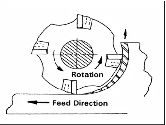
Figure 2.1: Up milling (Ronald and Denis, 2006).
It is a common practice for many years in the industry to mill against the direction of
feed. This was due to the type of tool materials then available (HSS) and the absence of
antibacklash devices on the machines. These methods are known as conventional or up
milling as in Figure 2.1. Up milling is also considered to as conventional milling. The
direction of the cutter rotation opposes the feed motion. For example, if the cutter rotates
clockwise, the work piece is fed to the right in up milling. The chip formation in up
milling is opposite to the chip formation in down milling. Nevertheless, for up milling
the chips usually come to the user if they could not stand at the right side because the
cutting tool starts to mill the small chip thickness. Then, the chip thickness gradually
increased. This type of milling method is not preferred because it may injure the user
while machined the sample because the rotation of cutting tool makes the chips come to
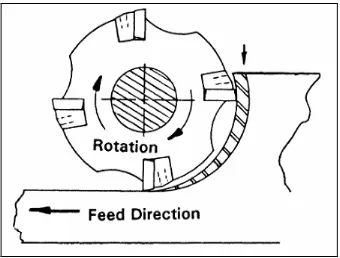
[image:23.612.159.500.69.326.2]Figure 2.2: Down milling (Ronald and Denis, 2006).
Ronald and Denis (2006) noted that climb milling or down milling is now the preferred
method of milling with advanced cutting tool materials such as carbides, cermets and
CBN as in Figure 2.2. The insert enters the cut with some chip load and proceeds to
produce a chip that thins as it progresses toward the end of the cut. This allows the heat
generated in the cutting process to dissipate into the chip. The cutting tool will rotate
anticlockwise and the work piece will come from right side. The cutting tool will climb
the work piece along the machining process. The user will be able to avoid the chips by
standing in front of the machine and at the right side.
Climb milling is preferred when milling heat treated alloys, stainless steel to reduces
work hardening. Climb-milling forces noted by Ronald and Denis push the work piece
toward the clamping fixture, in the direction of the feed. Conventional-milling
(up-milling) forces are against the direction of feed and produce a lifting force on the work
[image:24.612.158.498.68.326.2]