Rochester Institute of Technology
RIT Scholar Works
Theses
Thesis/Dissertation Collections
10-26-2010
Facilitating Rapid Response with a Relational
Indicator Database Schema and Client Agents
Jason Batchelor
Follow this and additional works at:
http://scholarworks.rit.edu/theses
This Thesis is brought to you for free and open access by the Thesis/Dissertation Collections at RIT Scholar Works. It has been accepted for inclusion in Theses by an authorized administrator of RIT Scholar Works. For more information, please [email protected].
Recommended Citation
Facilitating Rapid Response with a Relational Indicator Database Schema
and Client Agents
By
Jason Batchelor
Thesis submitted in partial fulfillment of the requirements for the degree of Master of Science in
Networking and Systems Administration
Rochester Institute of Technology
B. Thomas Golisano College
of
Rochester Institute of Technology
B. Thomas Golisano College
of
Computing and Information Sciences
Master of Science in
Networking and Systems Administration
~ Thesis Proposal Approval Form ~
Student Name:
Jason BatchelorThesis Title:
Facilitating Rapid Response with an Indicator Database Schema and Client AgentsThesis Area(s):
Networking Systems Administration(circle one) Security Other ________________________
~ MS Thesis Committee ~
Name
Signature
Date
Yin Pan
Chair
Eric Hutchins
Committee Member
Jason Koppe
Committee Member
Luther Troell
Thesis Reproduction Permission Form
Rochester Institute of Technology
B. Thomas Golisano College
of
Computing and Information Sciences
Master of Science in
Networking and Systems Administration
Facilitating Rapid Response with a Relational Indicator Database Schema
and Client Agents
I, Jason Batchelor, hereby grant permission to the Wallace Library of the Rochester Institute of Technology to
reproduce my thesis in whole or in part. Any reproduction must not be for commercial use or profit.
Abstract
The threat encompassing the critical computing infrastructure nations depend upon has shifted. A new
dynamic of adversaries leveraging a playbook of highly sophisticated, organized, and well funded cyber attacks has
emerged. These adversaries penetrate networks using exploits, tools, and techniques that are not detected by
traditional client and network security software. Compromised networks stand to lose irreparable amounts of
sensitive information and trade secrets if confidentiality is lost. The threat has shifted, but detection and response
mechanisms have largely remained the same. They have maintained the same largely ineffective result these
advanced adversaries count on.
To counter this, the development and implementation of a client based relational indicator database schema
was researched and designed. This schema represents information that, when aggregated over time, signifies an
archive of actionable intelligence. The relational model contains tables of client snapshots, each of which are
correlated to their respective subset of indicator metadata consisting of differing types of system information. A
complete proof of concept implementation was developed using an agent based reporting structure. The agent,
named CAITO (Collector of Actionable Intelligence for Threat Observations), reports relevant system information
to a database using the developed schema. CAITO is also capable of processing administrative instructions by
accessing a remote XML based configuration file. A front-end web portal was also developed to demonstrate the
facilitation of analyst queries with the derived dataset. The technical implementation is designed to be integrated
into any Microsoft Windows environment. It may be deployed as a Microsoft Self Installer through Active Directory
Table of Contents
Introduction ... 1
Problem... 1
Review of Literature ... 2
Document Outline... 6
Research and Design ... 7
Database Design Considerations ... 8
Relational Database Schema Design ... 10
Node Reporting Layout ... 10
Relational Model ... 10
Final Database Design ... 15
Development Strategy ... 16
Schema Development ... 16
Database Platform... 16
Analyst Front-end ... 18
Architectural Dependencies ... 18
Agent Development ... 20
Proof of Concept Considerations ... 22
Data Reporting Process ... 22
Reporting Architecture Details ... 23
Agent Persistence ... 24
Security Challenges ... 25
Results ... 29
Agent Software ... 29
Program Flow ... 29
Class Overview ... 31
Dependencies ... 33
Web Portal ... 35
Functionality ... 35
Conclusions ... 38
Future Work ... 39
Security ... 39
Integration... 39
Correlative Analysis ... 39
Benchmark Statistics ... 40
Instructions ... 42
Example InfoFile.xml ... 42
Example Client Sys.xml File ... 43
UniversalSchema.xsd ... 69
Agent code ... 73
Builder.cs ... 73
CAITO.cs... 78
Client.cs ... 79
DataConnection.cs ... 81
FileAggregation.cs ... 84
NetworkAggregation.cs ... 87
ProcessAggregation.cs ... 90
RegQuery.cs ... 92
ThreadAggregation.cs ... 94
WindowsServiceInstaller.cs... 96
Web Portal Code ... 97
Server Side... 97
Web Page ... 100
Acknowledgements
Thank you:
My family and fiancé, without which, I would not have been able rise to this point.
My friends, professors, and academic colleagues for their support throughout the years.
Past and present co-workers and employers, for further developing me professionally and technically.
“In the end it all comes down to one thing. You can‟t run from the wind, you face the music, trim your sails, and keep going.”
Introduction
During the first few moments of a computer security breach, responders seek to leverage any available set
of resources and tools in order to reduce the exposure of sensitive information and regain control. These tools often
process incident related indicators, such as Internet Protocol (IP) addresses, Uniform Resource Locators (URLs), or
email metadata, and return related results. The goal for the analyst is to identify exactly which systems have been or
are currently being compromised by an adversary. These systems also serve as a potential area to learn more about
the tactics, techniques, and procedures of the adversary. The information gathered from affected systems feeds the
incident indicator list which in turn, is used to detect and react to adversary presence on the network. The primary
purpose of these indicators in the early stages of an incident is to help establish scope. It is through the use of
querying different logging capabilities on the network with the appropriate indicators that overall incident scope is
established.
Problem
Achieving this result, especially in today‟s large scale and globally interconnected networks is extremely
difficult. The process is also complicated because many tools provide visibility in one specific area but not others.
Some of them may only provide visibility for a certain portion of the network. This forces analysts and companies to
invest money and time into other solutions which focus on different areas and use them in parallel to draw
correlations for the development of ideas about how serious the incident is.
Many tools responders use focus on the aggregation of network traffic. While this is useful, collection
points are typically set up at the perimeter of a network to maximize visibility. This technique is inadequate at aiding
in the establishment of scope. A defined incident scope necessitates not only knowing what was compromised, but
why it happened, and what the damage assessment was; all of which inform mitigation decisions.
When an undetected adversary compromises an internal system and begins to propagate laterally on the
intranet, network visibility is likely limited. The technique fails completely in identifying incidents where there is
little or no network fingerprint; such as USB based malware or an insider threat. Today‟s perimeter logging
In today‟s IT environment, the consequences of a security breach have never been higher, and incident
responders need a faster, broader, and more effective method to derive incident scope and establish a timeline to
understand the incident in its entirety. A logging framework needs to be created for the client, which provides a
verbose set of information about the client‟s current state.
The purpose of this study will be to identify gaps in client side data aggregation, and fulfill these gaps by
developing a relational indicator database schema that is capable of aggregating relevant computer incident
metadata. The utility of the schema will be augmented through the use of dedicated, time based, reporting agents.
Review of Literature
A survey conducted by Symantec suggests that now more than ever sophisticated and targeted attacks
penetrate the security measures on computer networks [1]. These attacks have resulted in the exfiltration of
personally identifiable information, such as the 30,000 SSNs that may have been compromised on a college campus
[2], or sensitive corporate information [3]. The threat of cyber espionage perpetrated by highly motivated and
advanced adversaries cited in the paper entitled “Shadows in the Cloud: Investigating Cyber Espionage 2.0,”
published by the Information Warfare Monitor and the Shadowserver Foundation, gives a starting perspective
pertaining to the capabilities and focused data collection methods employed by cyber criminals [8]. Documented
evidence concerning cyber espionage networks that have proliferated across government, business, and academic
networks [8] are of chief concern. The stakes are higher than ever before, and logging capabilities are vital to the
identification and remediation of these breaches.
Security Information Management Systems (SIMS) are designed to facilitate searching, data reduction, and
correlation of information [7]. They play a major role in identifying evidence of malicious activity. Event
identification, aggregation, and correlation methods that are scalable, and depict near real time activity for incident
responders continues to be an issue of priority for researchers and corporations. For the analyst, the more verbose a
given data set is, the higher the likelihood they will be able to use indicators they find to query for other
compromised hosts. It is necessary to dedicate large amounts of storage to the operation of SIMS databases. Much
of the data may initially seem too verbose and unneeded; however, the writer‟s experience as an incident responder
A comprehensive SIMS dataset assists in building momentum towards establishing an overall incident
scope. When a network intrusion occurs, defenders are placed in a position where they need to catch up to the
adversary, to determine what advantage enabled the adversary to progress that far in the intrusion. If the defenders
can recreate the entire sequence of events in the intrusion and develop new mitigations around the adversary's
process, which forces the adversary to adjust. On the other hand, if defenders cannot recreate the entire intrusion,
any aspect left unmitigated is an aspect the adversary need not adjust. Completeness of analysis drives completeness
of mitigations. If the defenders mitigate faster than the adversaries adjust, adversary‟s actions become dictated in
accordance with the defenders decision cycle. This paradigm shift enables defenders to regain control.
With time and research, SIMS tools will do a better job in fulfilling the needs of incident responders.
Mandiant Technologies has recently come out with a device that takes a slightly different approach to the traditional
SIMS architecture, but has also driven innovation in the field of host based incident detection and response. The
device is called the Mandiant Intelligent Responder (MIR), and it is designed to aggregate alerts that are generated
by its agents. The agents are deployed to computers within the enterprise, and are configured to alert on file system
indicators which may represent anomalous activity [4].
When designing a reporting architecture, this paper will follow a similar approach --assigning agents to
clients; and then having them report to a collection point. In addition to indicators present on the file system,
automated scripts can be assigned to the agents to gather a snapshot of the file system, running processes, and open
ports. MIR is one tool that is able to give vital actionable host based intelligence to the incident responder who can
then make decisions on remediation and mitigation.
While MIR is a significant step forward, this research proposal aims to develop a time based approach that
scales, and is able to consistently aggregate client side information to a centralized relational database. MIR applies
a list of known bad indicators and reports which systems contain those indicators. The goal of this project is to
design a schema and architecture that builds and stores a comprehensive snapshot of a system across a period of
time. This allows analysts to identify approximately when a system was compromised using a specific indicator, and
lends the ability to cross reference that snapshot with a snapshot of the system before hand. Doing so may yield
Scanning using MIR is done on a manual basis [4]. Manually scanning for one period in time will not
capture offline clients. This will also fail to capture indicators on systems adversaries have visited, and executed
some basic techniques to hide their presence afterwards. A specific indicator might also only exist on a system for a
day before deleted. Furthermore, the analysts must know the indicator in advance to find it on the affected systems.
The proposed methodology in this paper will increase the chances of the indicator being captured by automating
collection and collecting all indicators, thus enabling a better definition of incident scope. The MIR solution is able
to gather information on deleted files [13], however, this information can be overwritten on the file system given a
reasonable amount of time. The presented solution is more likely to have past records of a clients state since scans
and uploads are performed periodically. As analysts uncover new indicators, they can leverage this historical state to
identify systems that may not currently have that indicator but did at a previous point in time. Identifying incident
scope requires identifying all affected systems, past and present. The matrix below represents some of the
fundamental differences in approach with MIR vs. the proposed solution, CAITO (Collector of Actionable
Intelligence for Threat Observation).
Interval Visibility Usage Historical Data CAITO Automatic Daily Snapshot Daily Client Intelligence Fully Supported
MIR Manual Limited Collection Reactive Intelligence Limited
In order to develop a relational database schema that gives a comprehensive view of a client‟s state, an
examination of what is important to an analyst is essential. There are few realms of computer analysis which share
as much symmetry here as the area of computer forensics. By examining what data attributes and elements of the
client Operating System (OS) and file system are most vital, one may begin incorporating these ideas into a schema
design.
A study conducted by Yinghua Guo, Jill Slay, and Jason Beckett entitled “Validation and Verification of
Computer Forensic Software Tools - Searching Function,” assists in identifying client data elements that should be
aggregated. The study focuses on providing a framework to ascertain whether a given piece of forensic software can
be validated as forensically sound in a given domain. The study provided a hierarchal overview of the important
elements of a client node that forensic analysts commonly examine. Some of these areas included registry
points can be aggregated off each client in the fashion and frequency deemed appropriate. However, the research
here will help guide thoughts as to what may and may not be worth considering.
Another study entitled “Investigating Sophisticated Security Breaches,” by Eoghan Casey denotes the
importance of clear and comprehensive logging throughout the enterprise. The study also asserts that present SIMS
solutions such as Cisco‟s CS-MARS and nFX from NetForensics, are not designed with enough forensics principles
in mind since only some attributes typically stored assist in digital investigations [6]. A schema designed to
aggregate client information would aid in facilitating the rapid response of digital investigations. A data point such
as virtual memory from clients is noted in the study as being a rich resource of information on compromised hosts
[6], and is worth considering adding to the schema.
Currently, adversaries are exploiting the lack of our forensic readiness [6]. The use of a client indicator
database to identify an adversary‟s tools on a compromised host facilitates a more effective response strategy. A
standard IP address firewall block can be simply thwarted by a piece of malware contacting a new command and
control address once the original IP times out. At this point, not only is the network still compromised, but the
security team has alerted the adversary to their activity, and they may take extra steps to obfuscate their presence on
the network. Field research has suggested that sophisticated attackers may migrate hosts to new command and
control channels and install new malware, neither of which may be publicly known [8]. The use of a SIMS database
designed on client side forensic principles would aid in a quicker identification of compromised hosts, which will
allow for a more coordinated and effective incident response.
The creation of a time based agent reporting system that leverages a schema with forensic principles will
also assist analysts in the profiling of a system. The paper entitled “Computer Security Incident Handling Guide,”
published by researchers at the National Institute of Standards and Technology, states that networks and systems
should be profiled at a healthy state to facilitate the identification of malicious changes [7]. Taking this level of
profiling down to the client affords incident responders the ability to more accurately determine the time of
infection. In addition, it allows analysts to understand what is and is not expected behavior on a client [7].
Automation of client profiling also reduces the need for manual interaction with a compromised host, an action that
Since more advanced and persistent attack styles are being observed as the computing industry matures,
reliance on SIMS to identify breaches and the scope of existing compromises will become more and more vital to
the overall health of an organization. The latest research and products represent an exciting and innovative trend for
the future of SIMS. As attacker profiles shift to the use of more sophisticated and targeted malware, the more
thorough and effective defenders need to be with the information they store in SIMS databases.
The collective attitude towards information security needs to be tailored more towards rapid incident
response, now. A client based indicator database is the key to establishing the appropriate amount of visibility
needed to combat advanced threats. Network compromises are now inevitable; it‟s a matter of when, not if.
Document Outline
The remainder of this paper is divided into five main areas. Research and design is the first, which explains
many of considerations and strategies that needed to be researched pertaining to the database and the proof of
concept development. This section also covers the design of the relational database schema and the proof of concept
program. The results page is the next main section which gives a detailed overview of the technical results
pertaining to the proof of concept. The agent software installed on the client is explained, as well as the web portal
template that was developed for analysts use. Conclusions are then drawn and future work is discussed. Finally, the
Research and Design
There are two central elements to this thesis document. The first is the development of a forensically
principled relational database schema. The term „forensically principled‟ pertains to the aggregation of select host
based information. Storage of this information is mapped using a relational modeling methodology. The second
element of research is the development of a practical proof of concept architecture and its implementation in the
enterprise.
Both areas contained their own unique set of considerations. However, decisions regarding one area also
had a significant chance of impacting the other. For instance, while considering the aggregation of a particular data
set, one also needs to consider how plausible that aggregation might be on an automated and consistent basis, and
whether or not that would scale. Also, the data set needs to be aggregated in an efficient, low impact way for the
client. Programmatically, it is also desired that methods and functions required to aggregate a certain data set are
supported natively to reduce agent size.
Realizing how simultaneously, independent and interconnected these two facets of this thesis is, the writer
decided to research and develop them in parallel. This approach lead to a more integrated end result that others will
be more likely able to manipulate, and adapt for use in their own environment. It also allowed the writer to make the
most of the time he dedicated, by partially mitigating the need to double back and restructure portions of the schema
or proof of concept due to an issue pertaining to implementation or feasibility.
This section breaks apart the database schema and the proof of concept portions of the thesis into their
respective considerations and designs. Some of the considerations are unique to one specific area, but they will
always in some part play a role in the research and design of the other. The first area touched upon is the database
schema considerations and design, followed by development strategy that applied to the proof of concept
Database Design Considerations
At the outset, this thesis focused on two core questions: what kind of information is necessary to gather on
the client, and how can this information be structured using a relational database modeling methodology. However,
consideration of information gathering naturally led to questions of effective data aggregation and identifying
information which is most important. Finally, there is the analyst, the consumer, and the success of this thesis is
measured by how well an analyst could use it in the course of an incident response.
Ultimately, the writer needed to first evaluate the fidelity of the information used to aggregate before
making any other assessments. The information aggregated needs to be something the analyst can use to pivot on
during an incident. An example would be a directory an adversary creates or uses on target systems to pool data for
exfiltration or drop tools. Such a finding might yield further insight into what the adversary is targeting or what
other file system indicators the incident response team can query on. Rapid response is further facilitated as a result
of this.
Value of this information should not just apply towards providing incident responders with actionable
intelligence to use directly in incident response activities. It should also help facilitate the feasibility of
implementing host based mitigations using other security tools that are deployed. For example, analysis of adversary
activity indicates their tactics, techniques, and procedures involve the use of a specific malware specimen which
drops executables or dynamic link libraries in a created system directory folder. The incident responder should be
able to use aggregate information to make an impact assessment of possibly mitigating files with exe or dll
extensions that are written to that given directory. Such activities might be accomplished by developing custom rules
for tools such as McAfee‟s Host-based Intrusion Prevention System (HIPS).
Ideally, aggregation of all host based indicators would be achieved through the use of one single unified
query which captured all possible indicators. However, this is where feasibility and scalability issues come into play.
The research aims for automatic scans to be performed on a routine basis, so the ability to consistently store that
much information from clients may vary in accordance with the environment the end result is implemented on.
Some environments may possess the ability to consistently aggregate this much data to the database server and allow
the analysts to query the dataset in a minimal timeframe. Others may implement the solution on a database server
issue if scaled to environments supporting several thousands of computing nodes. Clearly, a flexible and instruction
based approach needs to be considered to afford administrators the ability to customize client visibility to a degree
due to volume and performance concerns pertaining to the server and network.
Client collection volume is a dual pronged concern, and while it may be partially mitigated by granting the
administrator the ability to limit the amount of directory information created, simultaneous reports from thousands
of clients presents its own unique array of issues. The primary concern is data collisions occurring on the database at
the time multiple clients choose to upload their data. In order to remedy this, some variance will be needed once the
appropriate reporting time has been determined by the client. A random back off interval implemented in the client
code would help distribute the amount of reports that are uploaded to the database around the same timeframe.
Finally, once the issues surrounding the information being aggregated are thought out, considerations made toward
the relational modeling of this information must be made.
Relational modeling is beneficial because it allows for transparent correlation of data between two different
data sets. The Database Management System (DBMS) governs the relational mapping of data, so long as a schema
definition is present. As the writer began assessing how to model the different types of information aggregated from
the client, it became clear the end result would emulate a combination of hierarchal and relational modeling. Each
client will have one or more snapshots associated with it, which together represent the overall scan. The snapshot
will contain related tables which contain more detailed information concerning data tables and attributes. Many of
the subsequent relationships between tables will be one-to-many relationships. One snapshot will have many
directories enumerated, each directory will contain many files, and each file may contain one or more alternate data
streams. Once the necessity of combining hierarchal and relational modeling methodologies into the overall design
Relational Database Schema Design
After all relevant issues regarding the creation of the database schema had been identified, crafting the
overall table mapping and structure began. The general node reporting layouts were established so that each client
could be uniquely identified and possess multiple snapshots (or scans). Individual snapshots contain more granular
information captured in relational tables represented in a hierarchal fashion. Once the mapping was complete, a
relationship diagram was created using Microsoft Access, and was also used to upload the schema definition to
server running Microsoft SQL.
Node Reporting Layout
In deciding how to map clients and subsequent snapshots effectively, the writer incorporated data
pertaining to them both into a single parent table. The snapshot table is the parent table which maps to sub tables in
the relational hierarchy containing state information of the client. They are taken over a pre-defined, yet consistent,
time period. Primary and foreign key constraints are automatically created to uniquely map data tables passed from
each client over time.
All clients are uniquely defined using the MAC address that they use to report. That attribute is used as the
identifier of unique clients in the snapshot table. So a client with a given MAC address can be queried for in SQL to
see what corresponding snapshots it has generated. The client hostname and reporting IP address is also recorded in
the snapshot table to better facilitate client identification. Pivoting on MAC address alone is not necessarily a
reliable enough indicator, since network cards get replaced from time to time. Hostname and IP addresses may also
be used as possible identifiers to zone in on a particular client. This approach was found to be the most consistent
and effective way to grant analysts the ability to map unique client identifiers, while taking into account that one or
more of these parameters may change over time.
Relational Model
The following section seeks to describe each of the tables with respect to the attributes they possess and
their relationship mappings. A figure representing the design layout of each table is presented initially, along with its
Snapshots Table
Figure 1 – Snapshots Table
The Snapshots table is the parent table in the entire relational hierarchy. It maps directly to the following
tables: ProcessList, Directories, ActiveTcpConnections, TcpListeningConnections, and UdpListentingConnections.
All relationships from the Snapshots table to other child tables are one-to-many. The SnapID attribute is the primary
key for this table and it used as the foreign key in all sub tables. SnapDate represents the date and time that that
client began generating the report for upload. ClientMAC is the unique MAC address assigned to the first active
IPv4 enabled Network Interface Card (NIC) in the client‟s hardware profile. The IPAddress attribute represents the
clients IPv4 address and is derived using the same method as the ClientMAC attribute. The Hostname attribute
represents the computer name given to the client by the Windows Operating System (OS).
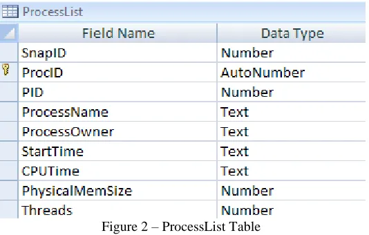
[image:20.612.175.442.465.635.2]ProcessList Table
Figure 2 – ProcessList Table
The ProcessList table is the child table of the Snapshots table and a parent of the ThreadList table. It
identifier. The PID is the unique identifier associated to a given process by the client when the agent scan was
invoked. ProcessName is the name assigned to the process, and ProcessOwner represents the client user the process
is running as. StartTime represents when the process was invoked and CPUTime shows how much total time was
used by the client CPU when processing instructions. PhysicalMemSize represents the associated physical memory
usage for a given process. Finally, Threads shows how many threads are running under the given process.
[image:21.612.174.443.230.359.2]ThreadList Table
Figure 3 – ThreadList Table
The ThreadList table is a child to the ProcessList table, and has no sub tables listed under it. It maintains a
many to one mapping to the ProcessList table. The ProcID value is inherited from the ProcID table as a foreign key
value. This table uses no primary key. The ThreadID is the identifier the client associates with a given thread.
StartTime represents the time when the thread was invoked, and CPUTime denotes how much time the CPU has
dedicated to processing instructions on the threads behalf. The Priority attribute contains the corresponding priority
value the client gave the thread. StartAddress displays the starting address the thread used when invoked,
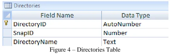
Directories Table
Figure 4 – Directories Table
The Directories table is a child to the Snapshots table and a parent to the Files table. A many to one
[image:21.612.170.442.558.646.2]value as a foreign key value and generates its own primary key value of DirectoryID. The DirectoryName value is
the directory path that was enumerated on a given clients.
[image:22.612.173.440.159.332.2]Files Table
Figure 5 – Files Table
The Files table is a sub table of the Directories table, and a parent to the AdsData table. To the Directories
table a many to one relationship is drawn, while a one-to-many relationship is drawn to the AdsData table. The Files
table inherits the DirectoryID value as a foreign key value while generating its own primary key value of FileID.
The FileName attribute denotes the name given to the file from the client. LastWriteTime, LastAccessTime, and
FileCreationTime denote the file Modified, Access, and Creation (MAC) times. FileSize represents how large the
examined file was in bytes. FileMD5 is the unique MD5 hash value generated for that given file. Finally, FileADS is
a Boolean attribute used to determine if a file possesses an Alternate Data Stream (ADS).
[image:22.612.174.441.555.640.2]AdsData Table
Figure 6 – AdsTable
ActiveTcpConnections Table
Figure 7 – ActiveTcpConnections Table
ActiveTcpConnections is a child table of the Snapshots table and has no child tables. The relationship
ActiveTcpConnections has to Snapshots is many to one, and it also inherits the SnapID value as a foreign key. There
is no primary key value for the ActiveTcpConnections table. LocalTCPConnection denotes the client address and
port number used on the client for the connection. RemoteTCPConnection holds the remote IP address and
corresponding port number. TcpConnectionState gives insight into the status of the existing connection.
[image:23.612.173.442.382.450.2]TcpListeningConnections Table
Figure 8 – TcpListeningConnections Table
TcpListeningConnections is a child of the Snapshots table with no sub tables. The relationship the table has
with Snapshots is many to one. It inherits SnapID as its foreign key value and maintains no primary key of its own.
TCPEntry lists the client IP and port number for the given connection.
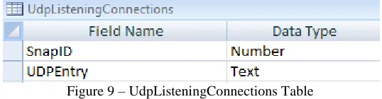
UdpListentingConnections Table
Figure 9 – UdpListeningConnections Table
The UdpListeningConnections table is a child of the Snapshots table and does not have any sub tables
[image:23.612.172.441.588.658.2]key. There is no primary key value for the UdpListeningConnections table. The UDPEntry attribute holds the IP and
port information for a certain connection on the client.
Final Database Design
The chart illustrated in Figure 10 below, depicts all nine tables that are part of the client indicator database
as well as their containing attributes. This diagram was generated using MS Access, as was most of the initial
[image:24.612.70.540.229.553.2]mapping of the schema.
Development Strategy
When making high impact decisions pertaining to programming language, tools, and capabilities to make
use of, the writer needed to consider the chief target for the proof of concept. Since most security concerns are
directed toward Microsoft operating systems and its line of products are the most widely deployed in commercial
enterprises, it made the most sense to target clients running some variant of the Microsoft Windows OS. The
decision to develop for these systems had high impact pertaining to the options and capabilities the writer had at his
disposal. When deciding on development languages and tools to leverage, the author primarily went with solutions
developed by Microsoft due to their tightly integrated product line and compatibility.
Schema Development
At a high level, the creation of the database schema was done using MS Access. The software offered an
easy and straight forward way to create data definitions and illustrate how they are interconnected with each other.
Changes made to attribute definitions in tables could be done with relative ease using the design view, and tested
using sample data sets.
Perhaps the largest advantage found when using this software was the ability to upsize schema changes to
an MSSQL database on the fly by using the MSSQL wizard in MS Access. This enabled a quick way to make
schema changes and then replicate then to the MSSQL database. When troubleshooting issues pertaining to incorrect
attribute or relationship definitions, this functionality is vital.
Database Platform
Through observing the capabilities uncovered in the MS Access software, exploration began pertaining to
the viability of MSSQL Server as a database hosting solution. The transparent support for MS Access table upsizing
was a large plus from a schema development perspective. When considering the clients need to upload its scan
results to the database, the writer needed to consider capabilities MSSQL supports that facilitate this.
Data content is able to be uploaded en masse using a supported Component Object Model (COM) referred
to as XML Bulk Load. When seeking to evaluate the utility of this capability and what other additional requirements
would be needed, the following excerpt from the Microsoft‟s MSDN library was instructive [9].
An annotated XML Schema Definition (XSD) or XML-Data Reduced (XDR) schema. The XML Bulk Load utility interprets this mapping schema and the annotations that are specified in the schema in identifying the SQL Server tables into which the XML data is to be inserted.
An XML document or document fragment (a document fragment is a document without a single top-level element). A file name or a stream from which XML Bulk Load can read can be specified.
XML Bulk Load interprets the mapping schema and identifies the table(s) into which the XML data is to be inserted.”
If utilized at the agent level, an accompanying schema definition file would need to be provided with the
resulting data from the scan before the data upload could take place. This means that some sort of schema definition
file would need to be developed so the database would understand the data mappings of the system scan. If this
methodology was adopted, the client scan file would also need to be generated in XML.
Another option was using the INSERT statement to upload XML data into the SQL database using an
OPENXML function. However, Microsoft states that using the Bulk Load utility lends better performance results
when inserting large volumes of data [9]. Ideally, one simultaneous upload would be best from an efficiency
standpoint. Less uploads from the client leads to a decreased chance of data collision on the database server. It also
allows for one unified upload process, which will be easier to control. This control will be critical when
implementing random back off sequences in client upload to mitigate data collisions and network congestion.
Upload capabilities for MSSQL are supported in C# and the ability to query this data is supported through
the SQL language itself. However, a usable front-end provided to the analyst is a reasonable requirement since it is
unreasonable to expect that analysts should query the database directly. MSSQL supports multiple web languages to
serve as front-ends for analyst‟s queries. So there are few restrictions in the area of web development when going
with MSSQL server.
The ability to change schema definitions quickly through the MSSQL upsizing wizard in MS Access, is
helpful from a development and testing perspective. The Bulk Upload support capability the C# programming
language has for MSSQL has the trade off of providing an additional schema file once the database upload takes
place. However, it provides a better performing methodology to use when uploading large amounts of data. It also
an array of open web programming languages that can be leveraged for front-end web development. Due to these
advantages, MSSQL server made the most sense to utilize as a database platform.
Analyst Front-end
For the proof of concept, a demonstration of the potential front-end capabilities a web platform could
leverage to display and manipulate aggregate data was desired. There were two main approaches examined when
seeking to decide on a language combination to develop a sample front-end: HTML/PHP and ASP.NET/C#.
The use of an HTML front-end with PHP to query the backend database represents the most open potential
since the development and hosting of the front-end can be done on free and open source platforms such as Apache
Web Server. ASP.NET/C# would require me to use the Visual Studio IDE and host on IIS, both of these solutions
are not free, but offer a great degree of usability and native support with MSSQL. With respect to ASP.NET/C#, the
ability to retrieve and display database information in a visually pleasing manor was seamless and can be
accomplished through the use of one integrated IDE.
One of the most attractive aspects of ASP.NET/C# was the ability to quickly develop SqlDataSource query
objects and place them into the web page layout. This facilitates real time data feeds from the database, so it would
be possible to easily display to the analyst statistics such as: how many reporting clients they are, how many
snapshots are stored in the database, and the total amount of Alternate Data Streams identified. ASP charts can also
be mapped to SqlDataSource objects, so graphs illustrating data trends can be easily rendered. Also supported is the
use of grid view layouts to display the results of analyst database queries.
The cited reasons offer a high degree of usability and native support when compared to the alternative of
HTML and PHP. For these reasons the writer decided to use ASP.NET and C# for front-end development. The
usage of both of these languages was available in Microsoft Visual Studio 2008. The IDE offers a simple way to
host and troubleshoot the web solution.
Architectural Dependencies
The agent based reporting solution follows the client server paradigm, so typical dependencies regarding
retrieve or store information. The agent will need to connect to the database server to initiate the upload; it will also
need to retrieve information such as the schema definition file and an instruction file with reporting details.
Regarding the client upload, a database server running MSSQL as the database platform is required.
Primarily due to the way data is uploaded from the client to the server using the MSSQL Bulk Upload COM object.
This is the only true dependency that needs to be addressed; however, the client needs to know where to store the
information and this information needs to be retrieved from an instruction file.
An instruction file containing details for the client to parse when invoked will need to be hosted. These
specific attributes are discussed in greater detail later in the document, but they primarily concern information
regarding where to report information, when to report it, and what information to aggregate. The client needs to be
able to parse this information in a unified and supported manor. The eXtensible Markup Language ( XML), provides
a standard framework, where elements containing attributes can be processed. Parsing XML documents is also
supported in many object oriented programming languages since it is a well accepted standard for representing data.
Due to these reasons, the writer concluded it best to host the configuration file in this format. The client will need to
retrieve the configuration file from a web server. Microsoft IIS was chosen as the hosting web server for the
configuration file since it was used to develop the analyst web front-end.
The common schema definition file will also need to be hosted for the client to retrieve. Before the agent
uploads the results of its scan to the database, a schema definition will need to be provided to the bulk upload
method. The XSD file will be hosted as a web download for agents when its primary method is invoked. IIS was
used to host this XSD file since it was already being utilized for web development and the hosting of the XML based
configuration file.
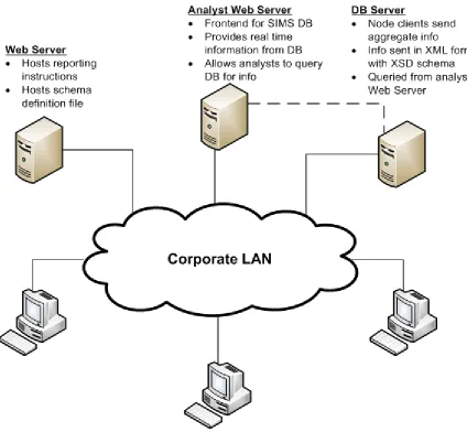
Reporting is primarily accomplished using the client server paradigm, and a centralized database server is
used to aggregate this information. Two files will need to be hosted for client retrieval, the XML based
configuration file and the schema definition file. Figure 11 illustrates the architectural dependencies required for the
Figure 11 – Sample Proof of Concept Architecture
Agent Development
Development of the agent needed to be in an object oriented programming language which took advantage
of a framework with both backwards and forwards compatibility, which is a standard part of any Microsoft
Windows operating system. It also needed to support the Bulk XML upload component which uploaded from the
client to the central database.
The .NET framework in Microsoft is a standard part of any Microsoft Windows installation, and is a
requirement for many of the applications which run on Windows. The C# development language is a highly
object. Programs developed in C# using the Visual Studio IDE can be compiled into Microsoft Self Installer (MSI)
files.
MSI files are useful for enterprise deployment via Active Directory. For an agent-based solution intended
to be deployed on Windows clients, this is a tremendous advantage, since most enterprises with MS Windows
clients use Active Directory for client management and authentication. MSI files are also highly configurable even
when compiled. For example, registry entries that are assigned values as a part of an install can be changed in the
MSI file itself using Microsoft tools such as Orca. This capability affords administrators the ability to manipulate
these values before enterprise deployment. The MSDN library provides the following description of Orca‟s
capabilities [10].
“Orca.exe is a database table editor for creating and editing Windows Installer packages and merge modules. The tool provides a graphical interface for validation, highlighting the particular entries where validation errors or warnings occur.”
The integrated capabilities C# affords programmers using the Visual Studio IDE are extremely beneficial
during the development phase. Administrators of Windows environments will also appreciate the customization
options afforded to them through the use of MSI editing tools such as Orca. Considering the many advantages
Proof of Concept Considerations
The considerations pertaining to the proof of concept portion of this thesis required careful and calculated
decision making, with ample amount of attention going towards items such as data reporting processes and overall
reporting architecture. Once the writer decided on a reporting architecture there were several challenges needing
consideration pertaining to usability and security. Local agent error handling was also something that needed to be
dealt with appropriately on the client. Achieving effective error handling means careful consideration of all the
things that could go wrong at and during run time. Anticipating security concerns that might arise when the agent is
deployed is also paramount. The agent needs to be robust, and withstand attempts at sub version by the adversary.
Establishing overall program flow and architecture are the first two objectives discussed in this section.
Next, an identification of the architectural and security challenges are made and described further. Finally, a section
that speaks to considerations given towards establishing overall agent persistence on the client is given.
Data Reporting Process
The intention when this proof of concept began was for the client to upload the results of their system scan
to a centralized database using the schema definition previously created. The process by which this is done falls on
the agent itself once a system scan is complete. At a high level, the reporting process is broken down into three
phases: schema retrieval, generation of the client scan file, and data upload.
When invoked, a GET request is generated from the client to the web server hosting the schema file. The
file is downloaded by the agent to the local client file system. Once the download is complete, the schema file will
be used to partially fulfill the requirements needed in order to upload data to the relational database. The schema
definition file provides the mapping for all data generated from the client to the relational database.
Generation of the system XML file is the next step in the process. The agent makes calls to subsequent
classes to aggregate client information, and this information is then stored within the appropriate XML element.
Retrieval of system information is done in parallel with the creation of the XML based system file. Once the system
XML file is complete, it is written to the file system in the programs working directory.
Finally, with the retrieval of the schema definition file and the generation of the system XML state file, the
the XML SQL Bulk Upload COM object can be used to upload all the system data. This upload is done in one
procedure call, and once complete, the system XML file and schema XSD is deleted from the file system.
Reporting Architecture Details
The agent will retrieve reporting instructions through accessing a XML based configuration file hosted on a
web server. The configuration file will contain XML elements with the following information: the time for the client
to report, the address of the database server, the name of the database, and the root directories that the client should
aggregate files and file metadata from. This approach allows administrators to adjust client report volume with
respect to the file metadata that is aggregated. The reporting time can be adjusted to compensate for times of high
bandwidth usage or for maximum client visibility. Database name and address can also be changed on the fly to
compensate for infrastructure changes or unexpected server malfunctions. While some configuration options are
retrieved through the access of a hosted configuration file, there are some local configuration parameters that need to
be supplied.
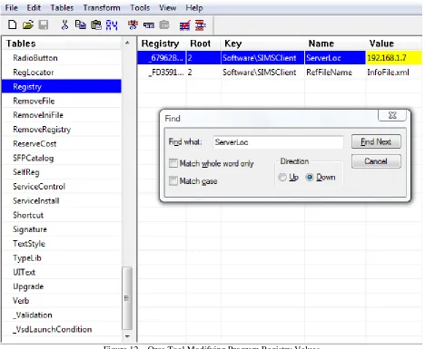
There are two main parameters that are defined as registry values once the program is installed. The first is
the address of the web server hosting the configuration file, and the second is the name of the configuration file
itself. These attributes are defined in the local registry of the client once the agent is installed, however, that does not
mean that they cannot be customized by administrators prior to deployment. As stated, since the installer is an MSI
file, the Orca tool developed by Microsoft as part of the Windows SDK Components for Windows Installer
Developers package, can be used as an editor to modify these attributes [10]. Figure 12 illustrates the usage of the
Figure 12 – Orca Tool Modifying Program Registry Values
The final element that impacts the overall architecture is the schema definition file, which is statically
named “UniversalSchema.xsd”, and stored remotely on a web server. The file cannot be stored locally on the client
for one central reason. The schema definition file, if modified, could corrupt the overall data upload. Hosting this
file in a central repository partially mitigates this from occurring.
Agent Persistence
The program is ran as a service in Windows, which is advantageous because the .NET framework has a
Windows service structure which integrates seamlessly into the design. The service can be viewable though
Windows in “Services and Applications.” By default the service can be automatically started once installation has
While persistence is established natively though the use of the Windows service framework, errors and
issues in the agent itself need to be appropriately handled to ensure the program stays operational. Potential errors in
the code were handled with try and catch statements where the appropriate exception was logged if encountered and
written as an event to the application portion of the Windows event viewer.
Some errors are dealt with transparently where the overall state of the program is unaffected, while others
may force the program to abandon the current runtime function and revert back to the main method. An example of
an issue handled transparently would be a directory that was specified to be aggregated from the client that did not
exist on the local system. If this exception is encountered, the directory is simply discarded and the program
continues unabated. However critical errors, such as the inability to retrieve the schema definition file, are recorded
and the program reverts back to the main method where it will wait until its reporting time before reattempting.
Agent persistence is very important to the overall client visibility the solution provides. It is crucial that
potential anomalies be accounted for and dealt with gracefully. Non critical errors are documented without much
impact to runtime, while high impact errors are documented and a reversion is made to the main method.
Security Challenges
Security issues surrounding the discussed implementation revolve around the agents data upload process
and some potential architectural vulnerabilities. By attempting to proactively identify areas of concern, the software
can be developed from the ground up with security threats and advanced adversaries in mind. The perpetual
argument of usability versus security is certainly applicable with the challenges identified. Multiple solutions are
presented to potential problems identified.
One of the concerns considered early on by the writer was the potential for an adversary who has
successfully compromised a client PC, to try to grab the registry values containing location of the remote web server
an agent queries for instructions. An adversary with sufficient privileges on a compromised client may be able to
view or modify this setting. Through the viewing of this registry value, and adversary could potentially try to
connect to the remote web server to view the file. By viewing the file they could gain a greater understanding of
To partially mitigate the potential of this occurring, the web server hosting the configuration file should be
doing so via secure HTTP. By doing so, conventional HTML get utilities the adversary may pull down to the
machine will need to be compiled with SSL support enabled. In the interest of time and scope, the development of
the proof of concept focuses on the retrieval of the configuration file over standard HTTP, however enabling this
functionality is relatively trivial.
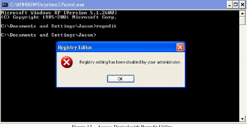
Denying the use of some command line tools is another way to inhibit adversaries. One way this could be
accomplished is through the use of proper security pre cautions implemented in Active Directory. By implementing
the group policy object entitled “Prevent access to registry tools,” and setting the value to enabled, users are
disallowed from using the command line tool regedit. Figures 13 illustrates the effectiveness of implementing this
[image:35.612.75.544.324.564.2]policy by showing the results pertaining to the command line utility regedit.
Figure 13 – Access Denied with Regedit Utility
Denial of read and write access to registry elements for standard domain users is the best and most
comprehensive mitigation against adversaries who seek to subvert the functionality of the proof of concept. The
measures taken in the group policy application described above do not mitigate on command line utilities such as
“reg”, which can be used to query specific registry values. Therefore, setting the proof of concept registry entries to
inhibit domain user accounts that may be under adversary control, from querying these registry values. Figure 14
[image:36.612.75.539.127.490.2]shows an example of this configuration.
Figure 15 – Appropriate Permissions for Registry Folder
Such changes can easily be made on a mass scale through Active Directory. These permission changes do
not impact the program runtime in any way since the process runs under the SYSTEM account in Windows. Figure
16 illustrates the result of these permission changes, when an attempt to query the registry key is made.
Figure 16 – Result for User Attempting to Enumerate Key Information
By implementing these permission settings, adversaries are inhibited from leveraging standard command
not have appropriate permissions to access the key values. So long as appropriate permissions are associated with
user accounts in the enterprise, potential damage to the functionality of the proof of concept and unauthorized
intelligence gains by the adversary should be largely reduced.
For the proof of concept to remain an effective intelligence gathering solution, it is imperative that
intelligence pertaining to aggregated directories remains undisclosed. Utilizing appropriate permissions to client
keys that hold this information is one way administrators may preserve this information. From a programming
perspective, it is important that residual scan and schema files that are uploaded from the client are removed once
the operation is complete. Both of these files will need to be removed from the client by the agent once data
processing is complete.
Since the program will be designed as a service that operates in the Windows “Services and Applications”
group. The potential exists for the service to be terminated on the client. In order to mitigate against an adversary
shutting off the service all together, appropriate provisions should be made on the local machine or through the use
of group policy in Active Directory to ensure that only enhanced accounts can modify and change the service.
Access Control Lists (ACLs) for the service can be created and applied to the group policy object. In the ACL,
specific users and groups can be added who have authority to start, stop, or pause the service [11].
Lastly, write access to the central database is given to clients with the agent deployed. While this is
necessary for the program to function, it may also represent a potential security vulnerability. There are two ways
authentication can be handled to the database server, through a hardcoded connection string or by using integrated
domain authentication. The most appropriate method largely depends on the environment where the solution will be
implemented.
The functionality of the program as well as the protection of aggregate data integrity were two key items
that needed to be considered from a security perspective. The writer was able to leverage the use of Active Directory
in many of the potential risks identified as a means to facilitate universal policy deployment creation and
implementation. This is one of the key advantages toward choosing to use Microsoft‟s line of products for
development. More security precautions can be implemented since the program operates on a single vendor OS
Results
The results section speaks to the final versions of the client agent and web portal. In the agent software
section, the program flow is presented, along with hierarchal overview of the all the classes created. Afterwards, an
overview of the references and dependencies the agent utilizes are given. The next section details how the sample
analyst front-end was laid out, and provides a basic template of how the aggregate data may be displayed in real
time to the analyst, as well as how analysts may query the database directly. In the final section, a discussion
regarding the schema definition file and a sample system snapshot is given.
Agent Software
The final version of the agent software is named CAITO (Collector of Actionable Intelligence for Threat
Observations). When compiled as an MSI, the software is approximately 548Kb, which is relatively lightweight and
an appropriate size for enterprise deployment. There are no advanced installation options that would complicate the
automation of deployment; all required libraries are compiled with the MSI package.
Program Flow
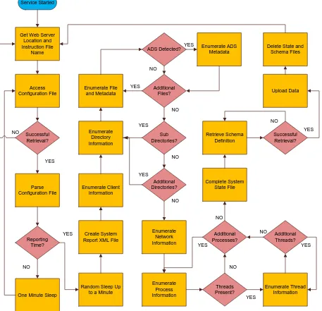
The overall flow of the CAITO agent begins once the service is started in Windows. When invoked, the
software collects two important attributes that are stored in the registry; the file name of the instruction file, and the
IP address of the of the web server hosting the instruction file. Once the attributes are retrieved, an attempt is made
to access the hosted instruction file. If this attempt is successful, then the XML elements in the instruction file are
parsed for further processing by the agent, if not then the client will attempt to require registry attributes and try
again.
The instruction file is parsed for the following information; the time to report, the database location, the
database name, and subsequent directories to aggregate. Once these attributes are parsed, a check is done on the
reporting time attribute, if the time on the client matches the reporting time given by the instruction file a random
sleep is initiated before further progress is made in the process tree. If the agent time is not a match with the
reporting time derived from the instruction file, then the agent sleeps for one minute before it accesses the
every other day, or weekly, then adjustments would need to be made in the requisite class. Moving forward
however, this functionality is something future versions of the agent could support in a more flexible manor.
Once the reporting time is reached and the random back off sequence is complete, the agent creates an
XML file on the local client where system data will be aggregated. After this is done, client information is
aggregated and written to the system XML file. Directory information is then enumerated next, and each directory is
processed once at a time. Files within the given directory are processed and checked for presence of Alternate Data
Streams (ADSs). If one or more streams are detected, then they are enumerated as well and written to the system
state file.
Once files in a given directory are processed, then the parent directory is checked for presence of
subdirectories. If there are subdirectories, then they themselves are enumerated along with any files and ADSs in a
recursive fashion until the end of the directory tree is reached. After the parent directory given by the instruction file
has all requisite information aggregated, the next directory in the instruction file is processed. If there are no more
directories to process, the next phase of aggregation begins.
Network information is aggregated from the client next. All active and listening TCP connection are
enumerated, and stored. Next, any listening UDP connections are listed and stored in the system state XML file. The
next element in the flow is the enumeration of processes.
Each process in the process tree is enumerated individually. A given process has the information pertaining
to it aggregated, and any subsequent threads running under that process are aggregated as well. Once all processes
and their respective threads have been examined by the CAITO agent, the aggregation phase of runtime has
completed.
The system state configuration file is completed and the last XML element is written to disk. The schema
definition file is then pulled down from its remote server to the local client. If this operation completes successfully,
then the upload sequence is initiated, and the agent passes the system state file along with the schema definition file
to the database. Failure to retrieve the scheme definition file from the host will result in a reattempt from the agent.
After the upload is complete, the schema and system state files are deleted from the client, and the overall process is
Service Started
Get Web Server Location and Instruction File Name Access Configuration File Successful Retrieval? NO Parse Configuration File Reporting Time? YES
One Minute Sleep NO
Random Sleep Up to a Minute YES Create System
Report XML File Enumerate Client Information Enumerate Directory Information Enumerate File and Metadata Sub Directories? Additional Directories? YES NO YES ADS Detected? Additional Files? Enumerate ADS Metadata NO YES YES NO Enumerate Network Information Enumerate Process Information Threads Present? Additional Processes? Enumerate Thread Information Additional Threads? YES YES YES NO NO Complete System State File NO Retrieve Schema Definition Successful Retrieval? NO YES Upload Data Delete State and
Schema Files
[image:40.612.80.537.80.521.2]NO
Figure 17 – CAITO Flow Chart
Class Overview
The classes developed for the agent were done so in a hierarchal fashion. There are four main levels of the
hierarchy. Each level denotes a phase of the agent run time process. Figure 18 illustrates how all the classes are
CAITO.cs
Builder.cs Client.cs
DataConnection.cs RegQuery.cs
FileAggregation.cs NetworkAggregation.cs ProcessAggregation.cs ThreadAggregation.cs WindowsService
Installer.cs
Level 1
Level 2
Level 3
[image:41.612.86.540.75.375.2]Level 4
Figure 18 – Hierarchal Overview of CAITO Classes
The first level encompasses the main classes that are used to install the CAITO program as a service in the
Windows OS, as well as instruction and details pertaining to the service itself. WindowsServiceInstaller.cs provides
important installation details such as; the account for the system to install under, the service description and name as
observed in “Services and Applications,” and the automatic start type for the service once installed. The CAITO.cs
class provides functionality to the start and stop methods that the service uses.
Level two refers to the base class, Client.cs. The majority of agent runtime is performed in this class, and it
is invoked by CAITO.cs. The Client.cs class handles procedure calls to the DataConnection.cs class and
RegQuery.cs class where attributes are retrieved and stored either locally or remotely. The Client.cs class also
handles the call to the Builder.cs class once the correct reporting time is achieved.
The third level contains the three classes that are invoked in by Client.cs. The DataConnection.cs class
handles the processing of the remotely hosted instruction file and the retrieval of the schema definition file. The
class also handles the upload of the system state file to the relational database. RegQuery.cs retrieves the local
file, enumeration of directories, and all calls to subsequent classes responsible for the aggregation client state
information.
The final level of the program hierarchy deals with the aggregation classes. FileAggregation.cs contains all
methods responsible for returning file metadata attributes, such as MD5 and ADS data. NetworkAggregation.cs
manages the functions which gather data on active and listening TCP connections currently active by the client as
well as UDP listening connections. Finally, ProcessAggregation.cs enumerates data associated with processes
running on the client; subsequent calls are made to ThreadAggregation.cs from Builder.cs for all threads belonging
to a given process.
Dependencies
Each class represented in the CAITO agent hierarchy maintains a list of references to various components
of the .NET Framework. There are also other Dynamic Link Libraries (DLLs) that are used by the agent which are
not a direct part of .NET and are therefore packaged with the MSI as dependencies. They are as follows:
Trinet.Core.IO.Ntfs.dll, sqlxml4m.dll, and xblkld4r.dll.
The Trinet.Core.IO.Ntfs.dll assembly library was written by Richard Deeming, and was recently rewritten
to support the release of .NET v3.5. According to the developer of the library, the .NET Framework does not
support the native retrieval of ADSs associated with files. The following explanation elaborates further on this [12].
“If you attempt to open a FileStream on an alternative stream, you will get a „Path Format not supported‟ exception. I have been unable to find any class in the CLR that provides support for alternative data streams…”
The addition of the author‟s library makes it possible to easily detect and aggregate information pertaining to the
existence of an ADS. The DLL is a third party extension, and compiled into the CAITO agent MSI.
The two remaining DLLs sqlxml4m.dll and xblkld4r.dll are not part of the .NET framework, but are
necessary because they both support the use of the XML Bulk Upload procedure used to store data from the client to
the database. These libraries were to be retrieved from Microsoft SQL Server, and were registered using the
regsvr32 utility. The xblkld4r and sqlxml4m libraries are dependencies of the main library needed to execute the