_______________________________________________________________________________________________________________
Building Information Modelling
Impacts and Opportunities
for Land surveying and the Cadastre
by
Ferenc Acs
Declaration
This report contains no material which has been accepted for the award of any other
degree or diploma in any tertiary institution, and to my best knowledge and belief,
contains no material previously publishes or written by another person, except where
due reference is made in the text of this report.
Signed
Ferenc Acs
Student Number: 114522
_______________________________________________________________________________________________________________
Abstract
Land surveyors are using sophisticated digital equipment and the best available technologies
to make observations in the field. These three-dimensional data are rigorously tested and
adjusted in the office using advanced mathematical and software tools.
In the case of surveying data provided to architects and engineers, a common workflow is for
the surveyor to derive representations of surfaces such as terrain in a 2.5D TIN format and to
deliver products to clients as 2D vector drawings. From these representations, architects or
engineers, reconstruct these simplified 2D drawings into a 3D terrain object.
The latest technological advances of building information modelling (BIM) methods create
exceptional opportunities for the land surveying profession. The utilisation of BIM not only
preserves the spatial integrity of the 3D components of the field observations but also offers
numerous additional opportunities. BIM allow the creation of 3D terrain objects which can be
used directly by the other stakeholders on the project. Terrain models within a BIM
environment can be equipped with attachments and attributes and therefore used to store
supplementary information. Custom made additional objects can describe certain features of a
property in 3D, such as a building envelope, easements, underground services or even soil
layers. Relevant addition data, such as long- or short-term climate data, precipitation and
wind conditions, sun-path, and shadow-casting data can be attached or linked. Customised
3D objects can indicate the internal space-structure of a building, and thus support an Indoor
Navigation system. Other customised 3D objects may indicate the ownership or strata title,
consequently supporting a future 3D Cadastre registration with accurate spatial data. BIM
procedures are automatically recorded therefore the BIM models are legally transparent and
traceable.
The project seeks to investigate the impacts and opportunities presented by Building
Information Models for land surveyors, and argues that the 3D modelling and common data
environment provided by BIM creates important opportunities for land surveyors and for the
Acknowledgements
I would like to take this opportunity to thank everyone who has provided assistance to me
throughout the course if this project.
Supervisor
Dr Jon Osborn UTAS
Technical Assistance and constructive comment
Veronika Vincze ABC Hobart
Johanna Acs UWA
Ken Webster UTAS
Trevor Parry UTAS
Dallas Wilson DWDD Hobart
_______________________________________________________________________________________________________________
Table of Contents
1 Introduction ... 1
1.1 Brief history of BIM ... 3
1.2 The Building Information Model ... 7
1.3 Land Surveyors and the potential impacts of BIM ... 8
1.4 Why BIM? ... 11
1.5 What is BIM ... 16
1.5.1 Parametric objects ... 20
1.5.2 Library Elements ... 21
1.5.3 Visualisation ... 22
1.5.4 Zoning (Indoor navigation) ... 24
1.5.5 Simulations ... 26
1.5.6 Clash detection ... 27
1.5.7 Communication - Collaboration ... 28
1.5.8 Computational Design - Algorithm Aided Design ... 29
1.5.9 Traceability ... 30
2 Aims and Objectives ... 32
3 Methodology ... 33
3.1 Literature review ... 33
3.2 Simple example: virtual construction with BIM ... 34
3.3 Case Studies: the BIM environment for land surveying ... 34
4 Literature Review ... 37
4.1 Key articles in the BIM literature ... 37
4.1.1 IFCv1.0 (Bazjanac & Crawley 1997) ... 37
4.1.2 BIM to Building Energy Model (O’Donnell et al. 2013) ... 37
4.1.3 3D GIS for a mine development (Duncan & Abdul Rahman 2015) ... 38
4.1.4 Multi-Level Indoor Path Planning Method (Zlatanova et al. 2015) ... 38
4.1.5 Utilising data modelling to understand the structure of 3D cadastres (Aien et al. 2013) 39 4.2 Computational Design – Algorithm Aided Design ... 40
4.2.1 Grasshopper - Rhinoceros ... 40
4.2.2 Grasshopper – Ecotect Analysis (Endesa Pavilion) ... 41
4.2.3 FME ... 43
4.3 Potential indoor navigation tools - Nationalmuseum@ ... 45
4.4 Return On Investment – ROI ... 46
4.6 YouTube Tutorials / Workshops ... 48
4.6.1 B1M ... 49
4.6.2 ArchiCAD (Architectural BIM authoring software) ... 49
4.6.3 REVIT (Architectural BIM authoring software) ... 50
4.6.4 TEKLA –Trimble (Structural Engineering BIM authoring software)... 50
4.6.5 FME - Safe Software Seminars ... 51
4.6.6 DDS – MEP ... 52
4.6.7 Intelligent BIM Solutions TV ... 52
4.6.8 Rhino - Grasshopper / 3rd party video lectures ... 53
4.7 Blogs... 54
4.7.1 Geometry Gym ... 54
4.7.2 Shoegnome ... 54
4.7.3 bimwise ... 55
5 Virtual Construction with BIM ... 56
5.1 Crafting three-dimensional virtual objects ... 57
5.2 Constructing a BIM of a building ... 60
5.3 Creating a BIM terrain model ... 63
5.4 Creating a BIM feature survey plan ... 67
5.5 Creating Library Elements ... 70
5.6 Level of Information (LOI) - Level of Development (LOD) ... 71
5.7 File exchange - IFC / BCF / BIMx ... 73
5.7.1 Common Data Environment and the Federated Model ... 73
5.7.2 PDF ... 74
5.7.3 IFC / BCF ... 75
5.7.4 BIM explorers ... 77
5.8 Zoning ... 79
5.8.1 Zone-stamps... 79
5.8.2 Building Envelope ... 80
5.8.3 Indoor Navigation ... 82
5.8.4 3D Cadastre ... 84
5.9 Workflow for small business... 94
5.10 Return of investment – ROI ... 96
6 Case Study 1: A Crossover (Small Residential Development) ... 99
_______________________________________________________________________________________________________________
7 Case Study 2 – Addition (Residential Development) ... 103
7.1 The Site / Data Acquisition ... 103
7.2 Terrain Modelling ... 103
7.3 Building Envelope ... 105
7.4 Deriving set-out data from IFC model ... 107
7.5 Summary ... 108
8 Case Study 3 – New Building (Residential Development) ... 110
8.1 The Site / Data Acquisition ... 110
8.2 Terrain Modelling ... 111
8.3 Building Zone-Stamps for Indoor Navigation ... 113
8.4 Zone-stamps for 3D Cadastre ... 116
8.4.1 Obtaining spatial information and geometry ... 117
8.4.2 Attached documents / Link to map projection ... 119
8.4.3 File sizes ... 119
8.5 Conclusion ... 121
9 Summary ... 122
10 Glossary ... 124
11 Bibliography ... 131
1
Introduction
Architects, engineers, builders and construction industry professionals need detailed spatial
information to support and manage their projects. Every natural or man-made feature or
object on a building site can influence the whole project. A meticulous three-dimensional
representation of the area of interest underpins reliable decision-making for all stakeholders.
Surveyors are amongst the first on every building site; their work is an integral part of the
building industry.Moreover, there is a growing demand to document the existing or ‘as built’
stage of buildings and their surroundings. Real estate owners, operators, property managers, financing institutions, insurance companies, city councils, fire departments and others require
detailed reliable spatial data sets that can be stored, analysed or distributed digitally. During
the lifespan of a project a great number of digital 2D and 3D data are created and published.
The latest developments in information technology allow the processing, storing and
distribution of high resolution, fully three-dimensional spatial data even in large file sizes.
The building industry design procedure produces and makes use of a collection of annotated
digital vector data with various attributes attached including their spatial distribution in a
coordinate system. The more complicated or complex the subject of the project, the more 3D
data is produced. A correlated group of 3D data can be organised as a digital object so that it
can be identified, interrogated, manipulated or visualised when needed. The spatial resolution
of an object can be set for its purpose; it can be very low or extremely high. Countless
attributes, written documents, drawings, images or digital files can be linked to an object
whenever required by the project. A series of linked digital objects, i.e. one produced and
shared collaboratively as a representation of the physical and functional characteristics of a
facility in order to form a reliable basis for decisions, is called a Building Information Model
or BIM (Agar et al. 2014).
Architectural and engineering software can deliver three-dimensional virtual models with
_______________________________________________________________________________________________________________
derived and exported to other software packages. The data exchange uses specific file
formats, accessible data storage and an integrated 3D model-based process as a common
platform. Any change or improvement of the BIM model can be accessible in real-time and
almost simultaneously for the stakeholders involved. The BIM model can be used for various
analyses, simulations, budget monitoring and documentation at any stage of the development.
Off-the-shelf objects can be added, or previously created objects can be re-used if required.
The coordinated data flow is traceable and accountable as both a whole and in detail. This
collaboration utilises various computing capabilities and tools in order to improve the quality
of the product and save time and resources for the project.
Nowadays digital collaboration between professionals is a common practice. The use of
networked computers is a daily routine; 3D digital maps, on line land-information services,
satellite navigation, Google Earth and Street View, and mobile applications have not only
generated more demand for a three-dimensional representation, but also built an awareness of
the advantages of complex digital features such as BIM amongst trades and professionals.
This projects investigates the current status and capabilities of Building Information Systems
and explores the integration of BIM into building design and construction, with a particular
1.1 Brief history of BIM
The Australian Institute of Architects define BIM as (Agar et al. 2014):
… a digital representation of physical and functional characteristics of a building. As such it serves as a shared knowledge resource for information about a facility forming a reliable basis for decisions during its life-cycle; from inception onward (buildingSMART)
Historically the physical and functional characteristics of a building as well as the
three-dimensional appearance of a future project were all in the head of the architect or builder.
Sets of drawings, plans, elevations, sections, sketches or perspective drawings were used as
representations of the appearance and as a communication tool between the participants of
the building process. The architect or the builder could be considered a ‘walking database’,
holding a conceptual understanding of the building and a substantial knowledge of the details
of the construction (Czmoch & Pękala 2014). The client or the other professionals had to
cognitively recreate the 3D appearance of the object using the presented 2D drawings. To
imagine an object in 3D from several related drawings, to ‘read’ the drawings as it were, can
be an intimidating procedure. To make the procedure easier, a scaled model of the future
project was often crafted. The museum of the Royal Institute of British Architects (RIBA)
holds a large number of scaled timber models. As Error! Not a valid bookmark
self-reference. shows, several different models can be prepared for the same project according to
_______________________________________________________________________________________________________________
The models can be a very detailed representation of the exterior appearance. In the past
whole new buildings were erected just to test complex structural elements or the strength of
building materials. The Tempietto (Figure 2) was built in order to model in a real-life situation the
structural composition of the central dome of the
St Peters Basilica (Lehmer 2013). Constructing
scaled models or three-dimensional sketches for
presentation is a routine procedure of architectural
design.
The scaled models however have several
disadvantages. First of all, the models are
generally observed from a bird’s-eye view which
is not the natural vantage point for a human. In
addition to this, constructing and frequently
modifying a scaled model is a time consuming exercise. The construction of scaled models
has become an industry in its own right. Up until recent times, specialised firms produced
‘artistic impressions’ of future projects. These elaborate models, however, are used mainly
for marketing or to create publicity (Figure 3).
It is easy to understand the enthusiasm of the
architects, engineers and the construction industry
professionals (AEC) when the first virtual reality
(VR) objects appeared on high-resolution colour
monitors. The end of the 20th Century ushered in the beginning of a new area. Tools and equipment never
seen before suddenly become part of everyday
reality. The 21st Century has also seen GPS, high-speed internet, wireless communication networks,
smartphones and high performance computer
devices used commonly and routinely world-wide.
Figure 2 The "Tempietto" in Rome (Source: www.studyblue.com )
A BIM is a complex network of virtual objects created and stored digitally. Therefore, the
early history of BIM is strongly connected with the capability of computer hardware and
software. In the early 1960s at the MIT Lincoln Laboratory a Human-Computer Interaction
experimental software was running on a room sized computer (Sutherland 2012). The
program was called “Sketchpad” (Sutherland 1963). This software already possessed the
basic features of modern computer aided design (CAD) software, such as the following:
constraint or object-oriented programming, graphical user interface (GUI), interactive
drawing pen (“light-pen”) and keyboard function control. The computer screen could
simultaneously and interactively display the designed object as a:
top view (Plan)
front view (Front Elevation)
side view (Side Elevation)
axonometric view (3D representation)
The design could be represented in ‘wireframe’ form or as a ‘solid object’. The ‘solid
objects’ could also be multiplied, zoomed in and out of, or even ‘subtracted’ or ‘added’ to each other. A series of operations could be semi-automatically executed following a
visualised flow chart (WGBH-TV 1964; https://youtu.be/USyoT_Ha_bA). The Pandora’s
Box of the digital 3D modelling had been opened.
The notions of extensive use of digital 3D models, the semi-automated geometric data
extraction of models, the library elements and the building database or Building Description
System (BDS) appeared in the mid-1970s (Bergin 2011). An important next step, from the
author of BDS, Charles Eastman, was the concept of Graphical Language for Interactive
Design (Eastman & Henrion 1977), from which most of the characteristics of the recent BIM
platform originate. The results of the research were however decelerated by the very high
costs and relatively low performance of computer hardware at that time, and the lack of
specialised personnel. An unforeseen breakthrough came from private companies in Eastern
_______________________________________________________________________________________________________________ ‘virtual building’ that could be constructed from fully 3D parametric objects and library elements. Within a very short period of time ArchiCAD has become an international
corporation, one of the leading forces behind BIM worldwide.
The other major player, Autodesk, was the principal CAD software producer for engineering
from the early 1980s. By the time AutoCAD R12 was released, the software had an advanced
3D solid modelling capability. At that stage of the software’s development an object could
only be built manually from node-to-node. The objects were static, as opposed to the
dynamic or parametric objects that maintain associations with other objects within a model.
With the acquisition of the object oriented and parametric REVIT software, Autodesk
literally entered into the new millennium. A whole family of parametric software products
are now produced by Autodesk, with REVIT the dominant software of the global BIM
market (Bergin 2011). The use of parametric objects as a design tool has become an integral
part of almost every software used by the AEC industry.
The nature of software development is constant change and the periodic hype of a new
software invention. Architects, engineers, construction professionals, facility operators and
owners (AECOO) and the authorities need to be able to make informed and sophisticated
decisions about if, how and when they will adapt their work practices and workflows to take
1.2 The Building Information Model
The concept of a future building is usually formulated in the head of the designer or architect
while interpreting the requirements or brief described by the client. The design is
fundamentally three-dimensional, a virtual object ‘stored’ in the brain. Until recently, various
tools were used to transform the design ideas or the solutions into 2D drawings or scaled
models. The client or other professionals are ‘reading’ these drawings, plans, elevations,
sections and details in order to recreate the virtual object again. Every change in the project,
every modification or improvement goes through this procedure again and again. The more
complex the project is, the more time consuming this procedure can be.
The Building Information Model is an attempt to create a model of the design that captures
every aspect of every detail. The BIM is a virtual realisation of the project. When a BIM
environment is used, the designed building or building elements are not drafted but virtually
built in the computer:
The scale of the virtual model is 1:1. Every element, the footings, the wall, the slab,
the roof and even the terrain around the building, is a fully three-dimensional virtual
object equipped with all the necessary attributes needed for the project at any stage of
the development.
Every stage of the virtual building procedure is recorded and can be visualised in 3D
immediately or as required.
The attributes of the objects can contain all of the necessary information including the
cost.
Prefabricated elements, such as windows, doors, furniture, light fittings etc. can be
downloaded from the manufacturer’s digital library and customised or just simply
added to the project. The parametric nature of the custom designed or the library
elements (objects) allow a consistent relationship between the elements, which may
result in a seamless workflow and accelerate the virtual building procedure. On-line
BIM libraries allow direct access to the product with all specifications, costs and the
_______________________________________________________________________________________________________________
enquired objects (or library elements) is traceable, which can be important regarding
the security and the quality assurance.
The virtual building can at any stage be transferred or distributed to other consultants
or to the client. This procedure can be a direct digital transfer, or via a structured and
secured cloud-database. The transferred BIM does not have to be recreated; it can be
read and visualised immediately. The architect or the builder does not have to be a
‘walking database’ because all the necessary details are attached to the BIM. The
individual files, objects, even 2D drawings can be hyperlinked (similar to a web
hyperlink) which enables an efficient navigation within the complex file structure.
This way the designers and the builders save time and reduce the risk of errors in the
building approval and construction processes.
The fast and efficient collaboration between the different fields of engineering and the
construction professionals is the result of on-line communication achieved through
networked computers. One of the major advantages of the BIM environment is that it
utilises already existing hardware devices and software. The file exchange and the
collaboration can be executed from a simple e-mail attachment, via the popular social
media or ‘cloud’ services (e.g. Skype, Facebook, Dropbox) to professional LAN
facilities. This feature allows user-friendly communication between professionals or
with the client, even for very small companies. Moreover, personnel who have freshly
entered the job market often have extensive knowledge and experience of various
forms of on-line communication. The next generation is also accustomed to the
various different product families and able to engage with the rapid and frequent
adaptation of new digital equipment and software.
1.3 Land Surveyors and the potential impacts of BIM
The profession of land surveying has a history that dates back thousands of years.
Observations have been recorded and presented in every epoch through the means available
at the time. In ancient Greece, geometry and map making became a sophisticated science.
Five hundred years ago surveyors already used triangulation (Gemma Frisius 1533) and the
map makers were using the Mercator projection (Crane 2003). The use of points, lines,
measure and represent the terrain for centuries. By the end of the 19th century arduous tasks, such as the triangulation of India, were completed with rigorous precision by a small group
of professionals with the use of simple optical instruments (Keay 2001). With the invention
of photography, the use of aerial cameras enabled the collection of large amounts of data
within a short period of time. Elaborate optical instruments and methods had to be developed
in order to extract the required information from the images. The next step in the 21st century is the common use of digital instruments and methods, which will enable the production of
far more precise and accurate survey data almost instantaneously and in full 3D. The past
demonstrates that the surveying profession is quick to integrate the latest developments of
science and technology1.
Land surveyors are working almost invisibly at every stage of a building construction.
Various tasks, such as cadastre surveying, site surveying, setout-surveying, construction
surveying and as-built surveying are an integral part of the AEC industry. Land surveying is
a mature science that possesses its own highly sophisticated and up-to-date digital
technology. The use of the latest communication and data transfer tools is a part of the daily
routine of the spatial science professional. The integration of Building Information Modelling
seems to be a natural step for land surveyors. The surveyor’s observations are usually points
with xyz coordinates and attached attributes. The observations are rigorously adjusted and
evaluated. The observations are then further processed, interpreted, and various lines such as
alignment, boundary lines, edge lines or breaklines are added in a proper projection using
specialised software. A digital terrain model (DTM) is generally created using a triangulated
irregular network (TIN) typically based on the Delaunay triangulation. The TIN surface is
usually overlaid with contour lines. A traditional survey product is a vector drawing that
contains various points, lines and polygons equipped with annotations. The product is usually
exported into a commonly used digital CAD file format.
Within the BIM environment surveyors are able to produce the terrain as a parametric object
with attributes such as the survey points, reference points, alignment lines, projection, the
TIN or the data validity calculations attached. Services such as utilities on the surface and
_______________________________________________________________________________________________________________
Existing buildings can be surveyed and added as custom-made BIM objects or point-cloud
data. In the near future it is likely that underground geological layers, masses, rocks and even
water bodies can be represented within a BIM. All the objects and their attributes can be
semi-automatically obtained from the model, including every change of the terrain, such as
Cut and Fill volumes and the surfaces of roads and walkways. The direct link between the
BIM environment and the GIS dataset may open the possibility of incorporating the outputs
of various GIS operations.
The BIM object oriented methods combined with the results of as-built surveying offer
useful information for the 3D Cadastre. The results of the 3D Cadastre combined with other
mobile digital technology might be used for an integrated Indoor Navigation within buildings
or dense built city environments. The Indoor Navigation solution might positively influence
the efficiency of Facility Management (FM) and Security and the Emergency Services (SES).
While further development of the BIM environment might be the task for the AEC industry
professionals, site surveying, underground service surveying, 3D Cadastre and Indoor
1.4 Why BIM?
Although a large number of great historical buildings have been erected in the past, design
and construction were for a long period of time a hands-on exercise. Scaled models,
empirical experiences, traditions and trial and error construction methods were used until the
early 19th century. The development of material sciences, structural engineering, the steel industry and the introduction of Portland cement can be considered the beginning of the
modern building industry (Kurrer 2012). By the end of the 19th century, complex engineered structures such as the Eiffel Tower could be erected. By the 20th century the building industry had become accustomed to mass production where a team of experts, architects, various
engineers and construction professionals were involved with the design of buildings. Sets of
2D drawings and various written documents were used as the main communication tool
between these professionals. Even though by the mid-90s early digital equipment and CAD
software presented the opportunity for digital communication and data exchange, the 2D
nature of the data exchange remained the norm in the building industry. The flow of
information between the stakeholders remained time consuming and difficult to follow
(Figure 4).
Figure 4 The flow of information and data during the design Mechanical
Engineers Architects Designers
Structural Engineers
Stakeholders Financial Inst.
Supply Chain
Survey Data
Gov. Authorities
Construction Professionals
_______________________________________________________________________________________________________________
Usually the architect receives instructions from the client and creates a design program. The
surveyor passes the site survey to the architect, who prepares the first sketches or a
preliminary design. These sketches are circulated to the engineers, builders and building
material suppliers for an initial budget estimate. When the initial building permission is
received from the local authorities, the future building is designed in detail by the architect,
in cooperation with other engineers and the owner. When the authorities approve the final
design, a lot of detail drawings are prepared in order to be able to finalise the bill of
quantities, the logistics, the time schedule flow-chart and the budget. The flow of information
usually has a very similar pattern between the various departments of the local authorities or
between the professions on the construction site.
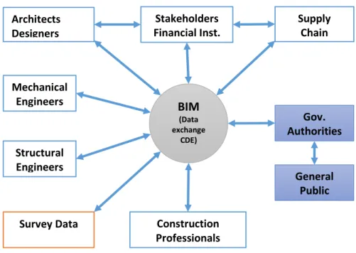
The characteristics of the BIM environment are a rationalized data flow and data exchange
procedure (Figure 5). A 3D virtual building contains many 3D elements such as footings,
slabs, ceilings, roofs walls, doors, windows and so on. An element can be composed from
several parametric objects.
Each object has a 3D geometrical description including its location within a reference frame
and can have several attributes and documents attached. The objects can be custom made by
a particular software or imported as prefabricated parametric library elements that are either
part of the software package or imported from a third party. The parametric nature of the
BIM (Data exchange CDE) Architects Designers Structural Engineers Mechanical Engineers Stakeholders Financial Inst. Supply Chain Survey Data Gov. Authorities Construction Professionals General Public
objects allows them to be altered or modified and that variation is automatically applied to
objects related to the modified object. Any object or virtual building element can be exported
using an independent file format. At the time of writing (June 2015) the Industry Foundation
Classes 2 edition 3 TC1 (IFC2x3) file format is recommended for data communication within
BIM environment (Liebich et al. 2007). The current major BIM authoring software such as
ArchiCAD, DDS, LISTECH NEO, GLODON, REVIT, and TEKLA2 can read and write the IFC2x3 file format3.
The 3D virtual model and the attached attributes and documents including 2D drawings and
images can be distributed from a common database, which enforces a ‘single version of
truth’ type of data in a structured and controlled manner. The BIM platform is accessible
24/7 from the very moment it is published. Every event, login, upload or download is
recorded; consequently the data flow is transparent and traceable. Variations, updates, issues
and events are simultaneously available for the designated participants. The data exchange or
distribution can have, but does not require, new hardware or network infrastructure. The BIM
platform routinely uses the already existing broad-band internet (ADSL2 in Australia) and
the widespread and commonly used, mostly free web applications and ‘cloud’4 services such
as OneDrive, Google-Drive, Dropbox, provided that sufficient data storage and security is
offered. Tablet and smartphone apps for BIM, among others the BIMx or SlimBIM2go, are
already available for off-the-shelf mobile devices. These apps do not require special training
or exclusive knowledge to use. The mobile variant of the documents or even the 3D model
are accessible using already existing mobile devices, and thus require no further investment.
The use of mobile devices and real time and simultaneous access to the data can also be an
advantage on a building site. Although the architectural or engineering data are distributed in
indexed packages sorted by reference number, the drawings - even the drawing fragments -
or the designated 3D elements can be hyperlinked. This feature makes a swift and
target-oriented navigation through the vast amount of data. Similar to the web-page hyperlink
feature, the hyper-linked documents can be physically located and stored in different
databases at will. If the security allows it, there is no need for the committed use of a
_______________________________________________________________________________________________________________
For the reasons mentioned above, the BIM environment can be considered a valuable
contribution to communication. The BIM concept and 3D models contain far more than a 3D
geometric representation of objects. It is an organised prototype of the building in terms of
footings, floors, walls, roofs and the attached attributes and documents (GSA-US 2007)5. The BIM model can be considered an index of the physical and the functional characteristics of
the design and construction. The BIM model is ‘computable’ and can be visualised by other
building analysis applications. It can be used directly for countless third party BIM
compatible software such as cost estimating, energy simulation, building code checking,
collision checking, and structural analysis. The exchange of data and the transferable records
of building information across the platform are intended to last throughout the lifecycle of the
building. The BIM environment should serve as an updatable and reliable source of
information for analysis and decision-making in design, construction, operation and
maintenance. The BIM is also a catalogue of the design, construction and the operational
status of the building (GSA-US 2007). Every participant, modification, change of event and
data exchange is recorded and traceable. The data is organised in time sequence, often called
the fourth dimension (4D) of the BIM. The 4D models support visualisation, coordination
and optimisation of the construction sequencing and supply of resources. The various
stakeholders, organisations, construction managements and facility management (FM) supply
chains can obtain exact, up-to-date and traceable logistical information from the start of the
design to the end of the lifecycle of the building (GSA-US 2009).
The cost estimate, budget and cash-flow monitoring can also be modelled or visualised when
the 3D BIM objects are logically linked with the 4D time sequence of information. This
derived product is usually called the 5D BIM model. This model enables integration of the
construction activities and related costs over the time (VICO 2014). The benefits of the 5D
model are that it provides a traceable, up-to-date documentation of cost planning and budget
control. This derived dataset can be a source of cost planning from a single owner-manager
to the financial institutions specialised for budget management of the construction.
Although the 4D/5D/6D/7D coding was probably introduced as a marketing ‘term’ to target
particular groups of professionals, it is widely accepted and used within the AEC industry
5
worldwide. The acronym of 6D BIM is assigned to Facility Management (FM) (Agar et al.
2014), although a paper from Europe allocates the 6D to sustainability assessment and the 7D
for FM (Czmoch & Pękala 2014). The 8D BIM is connected to Hazard Assessment and
Accident Prevention Through Design (Kamardeen 2010).
The growing number of ‘n’D BIM demonstrates that the BIM data is palatable for a wide
range of professionals. The structured information derived from a BIM model is capable of
serving several disciplines. Currently, the ‘n’D BIM operators may utilise the capabilities of
the free BIM-viewer software. Most of the free model-viewer software can open and
interrogate several BIM objects from different sources simultaneously. A wide range of
comments, screenshots and conflict detection notices can be located and saved. 2D and 3D
surfaces and polygons from (earlier version) CAD software also can be added, visualised and
saved into a single file together with the 3D objects. The capabilities of viewers seem to be
increasing rapidly. Free BIM-viewers can be a great help for a small business, FM
professionals or for the owners who otherwise would not be able to visualise the accessible
data. Free BIM-viewers also might help the professionals when the quality of the BIM model
is initially assessed. The errors, omissions (E&O) can be visualised or interrogated even on
mobile devices before the job is allocated for further process.
Although the shift from drawing table to CAD drafting was a spectacular, almost dramatic,
change, it also coincided with the honeymoon stage of the digital age. Practically everyone
wanted to see or have a desktop computer. Labour intensive tasks such as printing or copying
became very easy as the mutually compatible PDF file format could be used. The product,
the printed drawings, and especially the annotation, all appeared to be sophisticated and
visually pleasing. The drawings started to be transferred via the Internet and the drafting
table receded from view. Since most CAD software has 3D capabilities the use of 3D
parametric objects may seems to be a step that only requires a simple upgrade of the of the
CAD system. This however is not the case; the transition to a BIM environment interrupts the
design process from its commencement. The BIM model of a building is not drafted, but
digitally built in the virtual space. The building elements (parametric objects) are the virtual
_______________________________________________________________________________________________________________
The design, construction and building application approval processes require BIM
compatible authoring or viewer software
The BIM environment, due to the settings of the attributes for the 3D objects, requires
far more initial attention than a CAD drawing
The designated BIM authoring software require the essential third party library
elements of the specific building code jurisdiction
The collaboration requires BIM-ready partners
The third party library elements should be ready for download from the
manufacturer’s websites or databases
Government Authorities should be prepared to receive and accept BIM documents
The legal profession will need to deal with the issues of the acceptance of the BIM
objects as part of a legally binding contract.
As indicated, the technological background, the hardware, software and network
environment are ready for the adoption of BIM. The transition to BIM however requires a
greater level of participation and changes to professional practices. Although the benefits of
the transition are generally acknowledged amongst engineers and architects, it is only
cautiously being adopted within the AEC industry. The land surveying profession as an
integral part of the AEC industry can expect to be substantially and directly affected by the
growing role and importance of the BIM environment.
1.5 What is BIM
The CAD systems use simple vectors such as points and lines to compose drawings or 3D
elements. A design generally contains a great number of vectors, which are often created and
organised in a three-dimensional Cartesian coordinate system with a local origin. In a
traditional CAD system every shape, surface or object is drafted individually. When a feature
need to be tediously modified one by one. The CAD model may contain the geometry of the
design features, however the product is principally static, contains annotated plans, sections
and elevations as separate groups of drawing entities. The use of a three-dimensional design
tool such as BIM authoring software could be seen as a logical next step in the development
of CAD systems. The introduction of BIM has the potential to reshape the building industry
by literally adding a new dimension to the AEC industry practice.
There are several characteristics of BIM that makes this development significant.
Parametric objects
o BIM authoring software defines 3D objects with its parameters and relations with other objects. A parametric object maintains consistent
interactions between the objects and the model; if an object is modified the
related objects automatically implement the changes via the changed
parameters (ISA_Project_Team 2008). Each object can carry attributes,
attachments and hyperlinked uniform resource locator (URL) addresses.
The active link between objects and the digital network (Internet or local
network) make the parametric objects exceptionally useful compared with
a static CAD system
Library Elements
o Prefabricated Library Elements allow construction of accurate models. A library element is the virtual representation of an industrial product, such
as a steel beam or a sewer pipe. Most of the library elements are produced
and distributed by manufacturers, therefore the object represents the latest
model, which contains the actual attributes and specifications including its
price. The library elements are the direct interactive link between the
designer and the available building materials and fixtures.
Visualisation
_______________________________________________________________________________________________________________
professionals, clients, operators and the general public.
Zoning – Indoor Navigation – 3D Cadastre
o The 3D geometry of the enclosed spaces within and around a BIM project are called ‘zone-stamps’. The zone-stamps are usually stored on a hidden
layer within the BIM authoring software and are programmed to store
metadata about the area and immediate surroundings of a particular room
or space. The linked zone-stamp objects can be considered as the skeleton
of a project. While the various BIM, such as the architectural, structural or
mechanical models, can be significantly different within a project, they are
all directly linked to the chain of zone-stamps. Since the zone-stamps are
the skeleton of the project the AEC professionals are using this property as
an internal navigation tool within the project. The features (it can store
hyperlinked data) and the parametric geometry of the BIM zone-stamps
can be a valuable tool for indoor navigation systems. Moreover, the
coordinated and purpose built zone-stamps have the potential to be the
basic elements for 3D Cadastre systems.
Simulations
o At the very early stage of the development of BIM software the
programmers realised the potential of the parametric objects for various
building simulation. Recently almost every BIM authoring software
contains integrated simulation processes, such as Energy Evaluation, Fire
Rating, or Shadow Casting modules. The structural software can simulate
effects of various static and dynamic loads and vibrations in order to find
the best solution for a particular project. The BIM authoring software are
capable of connecting to other software or software modules as well,
therefore simulation can be governed by a remote, third party software via
Clash Detection
o BIM compatible software or BIM viewers are usually equipped with clash detection capabilities. This feature is used to semi-automatically detect
intersections or connections between 3D objects. This feature can be
increasingly advantageous when several complex models from various
sources are interrogated in order to detect the physical relationships
between objects. Similar to zone-stamps, special 3D objects, referred to as
an ‘aura’ can be created around a particular object (or object group) which
indicates certain characteristics, such as extreme heat or other hazard zone
or zones. Moreover certain rules, such as a Building Code or Fire Hazard
also can be coded using additional parameters to the zone stamps or other
groups of objects. A modified clash detection procedure therefore can be
applied in order to be able to investigate the clashes with the rules of a
particular jurisdiction.
Collaboration
o One of the most beneficial features of a BIM is the capability for communication and collaboration via the Internet. The Common Data
Environment (CDE) allows exchange of 3D models in commonly
recognised file formats. The parametric objects are equipped with
machine-readable data which allows extraction of attached attributes
semi-automatically. As was indicated previously, a BIM utilises the already
existing mobile communication and social media resources in order to
facilitate a wide range of methods of the collaboration which are familiar
to both the professionals and the general public.
Traceability
o BIM software are programmed to record every step of the design
_______________________________________________________________________________________________________________
1.5.1 Parametric objects
Within a CAD system two points create a line, and three points create a triangle. The area
within the triangle can be considered a two dimensional surface. Four points can compose a
three-dimensional surface or an object called a tetrahedron. Three-dimensional objects also
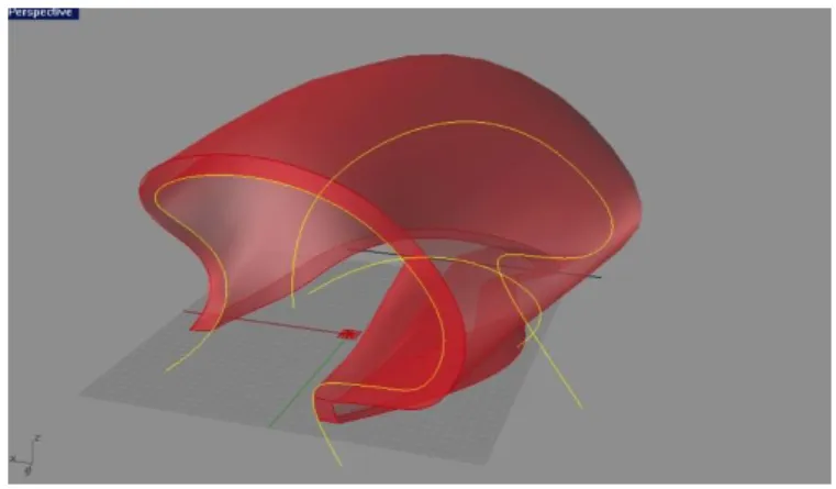
can be created using polylines and ‘extrude’ or ‘revolve’ commands (Figure 6). The objects
can also be ‘added’ or ‘subtracted’ from each other in order to form the shape required by the
design.
Figure 6 Free-form three-dimensional shapes can be produced with mathematical precision using polylines and the REVOLVE command (Source:
http://api.ning.com/files/Hcd6BcljSXcZ8RklX1*UDzn9nzFqAdRh3sQJy3kvKSVcytNlCvZk9ad9cuWpttxtLGYZePksyWElpQmBdMeAWCxSi
V06o7rN/2.jpg )
The objects created by a CAD systems are static; every modification has to be executed
step-by-step manually, whereas the object oriented parametric design technology embeds all the
features and capabilities of CAD systems into an integrated process-based solution:
“The geometry of a parametric object is defined in terms of named and interactive variables instead of fixed values…” (Model-Support-Group 2015a).
The parameters can be defined or modified interactively via an intelligent and user-friendly
GUI. The relationships of the parameters within the object and between the objects are
determined by the algorithm of the software.
“Any change, even the modification of a single parameter is automatically transformed to all related objects within the entire project.” (Model-Support-Group 2015a)
As a result all relevant parameters of the other objects are influenced and updated. The
with the use simple adjustments,
by applying complex ‘what-if’ rules, or
by executing Boolean operations within various constraints and criteria.
The operations within the software are configured, pre-determined and prearranged by the
software manufacturer. The designer is afforded a wide range of customised rules, operations
and modification. The configurations can be adjusted to specific tasks, according to the
definition of the software or by means of the operator’s knowledge.
Structural calculations, energy simulations, sun studies or visual impact assessment can also
be executed via an intelligent GUI, which invokes the appropriate variations of the
parameters and processes. Consequently the same object, or the whole project, can be altered,
modified or developed by architects, structural engineers or construction professionals. The
various industrial standards and local variations of the regional building regulations can also
be added to the software via the selection of the appropriate parameters, which further
customises the design procedure.
1.5.2 Library Elements
A building is generally constructed from standardised building materials and manufactured
using off-the-shelf elements such as rafters, bearers, beams, columns, lintels, doors,
windows, plumbing fixtures, various pipes and wires. All of these elements can be stored
digitally as parametric objects and stored in an on-line catalogue which, in BIM terminology,
is called the library. Even complex composite (multi-layered) walls, roofs, ceilings or
footings are stored as parametric library elements. The parametric library elements are fully
three-dimensional, hence the designer is not drafting, but digitally constructing the virtual
building.
_______________________________________________________________________________________________________________
local library and is ready to be re-used in other projects. These objects and their linked web
sites are gradually replacing the printed product catalogue library of the designer offices.
Moreover the digital library elements can contain the latest upgrade directly from the
manufacturer or can be replaced with other products without producing waste, and saving
costs and time.
1.5.3 Visualisation
An object, a small detail of the building or the whole project, can be simultaneously
visualised, rotated, and zoomed in or out of on the split screen of a computer. Objects are
usually colour coded in order to enhance the visual navigation within the virtual space. There
is no current general rule for the colour code; offices apply their own policy. The surface of
the objects however, can be wrapped with high-resolution photorealistic images for better
navigation or for presentation purposes. The high-resolution images usually represent various
surfaces such as face brick, blockwork, concrete, timber, stone or rough rendered surface, all
of which are provided by the software vendor. The painted surfaces also have their own
colour surface catalogue (library) which can be updated from the paint manufacturer’s
website (e.g. Dulux-online 2015).
Most of the BIM authoring software are equipped with accurate sun path data and shadow
casting capabilities. The local origin of the project can be linked to the exact geographic
location, which is usually expressed using longitude and latitude values. The sun position is
determined by the software when the local date and time (including Daylight Savings) is
keyed in. Some currently available software is able to emulate ambient light conditions or
add artificial light fixtures for night-time conditions. All light fixtures are proper parametric
objects and the default characteristics of the emitted virtual light, such as light direction,
angle, colour and fading are all pre-set by the manufacturer.
The precise position of a virtual camera also can be interactively determined. The settings of
the integrated virtual camera via GUI mimics a realistic digital camera. In the preview the
actual scene can be monitored. The process allows production of photorealistic images in
perspective projection for presentation purposes. Several virtual camera positions can be
allow the capture of images of a future project from given positions of the camera and the
sun. These images can be merged with actual images of the building site in order to
determine the visual impact of the building. This technology allows the user to produce
augmented reality images, in which the images of real scenes can be enhanced with the
objects created in the BIM software.
The augmented reality images produced by BIM authoring software are not ‘artistic
impressions’ or sketches, as all properties including the geometry of the objects are
representing the exact three-dimensional positions determined by the designer. Parametric
virtual cutting planes produced by the software enable the user to visualise the project in
sections and consequently the traditional plans, elevations and sections can be visualised and
printed out ‘on demand’. The software also allows the user to temporarily change object
properties such colour or transparency in order to facilitate the visual investigation or
enhance the virtual navigation between the objects (Figure 7 ). Objects that are occluded or underground, such as stormwater or sewer pipes, can be visualised using this method. The
exact future location of the objects, such as the inverts of a stormwater line, can be ’seen’
directly and instantaneously from the BIM model at any point if required
Figure 7 An augmented virtual reality map of the Las Vegas underground services on
_______________________________________________________________________________________________________________
1.5.4 Zoning (Indoor navigation)
A building is conventionally organised by floor levels or storeys. For a designer, the Floor
Level (FL) value determines the vertical separation of the sheets of plans, which may also be
referred to as Ground Floor Plan, First Floor Plan and so on. The architects and engineers
customarily design each FL or storey separately. The BIM authoring software allows the user
to see the storey below or above as a ‘ghost-storey’ in order to establish the relationship
horizontally (registration) between the storeys. The FL is usually a height value given in
metres above the temporary bench mark (TBM) of the project. In Tasmania, when the TBM
is linked to the site survey map by the land surveyor, the values are given as Eastings,
Northing6 and AHD837. In BIM authoring software a building is virtually constructed using parametric objects such as footings, slabs, walls, windows, doors, roofs and so on. The
objects usually enclose areas or spaces with various functions such as living room, bedroom,
bathroom or corridor. The ‘air space’ of a room can be considered an empty cell with a
usable function.
Within some BIM authoring software, an enclosed space or cell is treated as an object. In
order to distinguish this special ‘empty’ object, it is often called a zone-stamp. By default a
zone stamp object is a three-dimensional cell, which exactly matches with the inside area
enclosed by the walls, the floor and the ceiling of a room (Figure 8). The zone object is
mainly used for internal navigation within a building.
Figure 8 The ZONE object is indicated with blue colour within the 3D horizontal section of the building. (Source: GraphiSoft BIMx tutorial)
Every zone object has an ID number that matches with the room number used in traditional
CAD drafting. The Zone object is predominantly used to extract the list of rooms, as well as
calculate specific surfaces such as floor (e. g. carpet) and wall or calculate the air volume.
Zones can be colour coded to indicate the different functions of the zone. Colour codes can
be used to indicate various attributes such as fire rating, price range or ownership, etc. Zone
volumes are also used for the energy evaluation or for the design of the MEP features.
When the doors, the windows and indoor obstacles are attached as parameters to the zone
object, it can be used as a basic unit for Indoor Navigation. The software can calculate or
simulate the lengths, the direction and the cross section of the evacuation path for security
design purposes or for Emergency Services. The parametric Zone object will change its
shape automatically whenever a related object is altered or a new object introduced, and can
as a result update all related objects, calculations and design features.
These BIM zones are potentially significant for land surveyors. Within a project more than
one group of zone-stamp objects can be produced. When a strata title is composed by
property lawyers the document clearly describes the ‘metes and bounds’ of the property.
Consequently, a set of customised zone-stamp objects can be created that follow the 3D
boundaries of the ownership within the area of interest. The ownership zones can be
extended to outdoor easements, the common owned areas, or below surface to indicate
easements for underground services within the boundaries of the title. When a land surveyor
is involved in the creation of the ownership-zones, then in practice a 3D cadastral survey is
implemented. Further, an interactive link between the BIM environment and the 3D cadastral
_______________________________________________________________________________________________________________
1.5.5 Simulations
Energy Evaluation
Most BIM authoring software can produce an Energy Evaluation simulation based upon the
function and shape of the building, the characteristics of the building materials and the
finished surfaces. Special add-on software evaluates all objects both individually and
collectively within the given climate conditions of the area and the requirements of the local
authorities. This add-on software reads the given parameters of the project and implants them
into the required model environment. The functions (profiles) of the building are ‘read’ from
the Zoning, and the materials and the surfaces from the object groups. Usually elaborate
settings of the parameters can be used such as Surface Heat Transfer, Material Thermal
Conductivity, Surroundings Characteristics, Wind Protection, Horizontal Shading, all year
Climate Data (sun, wind, temperature, precipitation, due point, humidity),
Heating-Ventilation type and Energy Source factors. The software collects the data
semi-automatically from the settings of the objects and third party ‘cloud’ databases acceptable for
local requirements (Figure 9). This initial energy evaluation simulation can be run at any
stage of the design in order to keep the design within the required local parameters. Although
climate related Energy simulation modules are available in almost every BIM authoring
software other, more specific simulations can be found in specialised engineering software
equipped with BIM authoring capabilities.
There are various software available tailored for Structural or Mechanical Engineering. These
varieties of software can simulate the deformations or vibrations of the steel, concrete or
timber structures under loading or the influence of various fluid dynamics on pipelines. The
parametric nature of the BIM also allows a semi-automatic design procedure. The typical and
frequently repeated design can be ‘coded’ and customised to the new site adjusting just the
parameters. Various simulations can be executed with the ‘coded’ design through using a
systematic modification8 of the parameters in order to find the best solution. The final
product is either integrated or linked to the final BIM model, which is the key area of interest
for a land surveyor within the AEC industry.
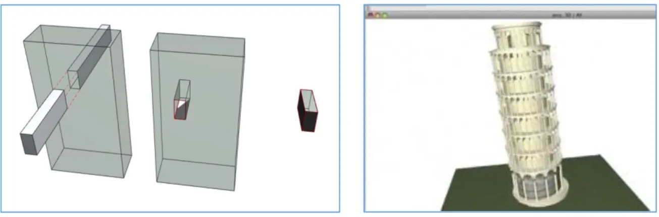
1.5.6 Clash detection
A project may consist of several closely related BIM models. Even a simple building can
contain a separate architectural model, a structural model and hopefully a model of the
terrain (Figure 10). These models are generally produced by different professionals, who use
different BIM authoring software packages. When the various related models are
simultaneously interrogated the automatic clash detection can be one of the first steps to
execute.
_______________________________________________________________________________________________________________
The software visualises and marks the detected
clash points and creates an automatic clash
detection report. The user can create a section and
navigate, orbit, and zoom in and out freely within
or around the 3D model. Filtered clash detection
procedures are routinely used by designers in
order to accelerate the identification and marking
of conflict areas between architectural, structural
and mechanical engineering models (Figure 11)
Land surveyors may identify building elements
protruding into easements or areas outside of the
building site. Clash detection can also executed
between a BIM model and the Building Envelope object (zone-stamp) in order to detect
clashes with any height restriction imposed by authorities.
1.5.7 Communication - Collaboration
A project requires communication and collaboration between several stakeholders. Even a
small building needs a designer, a structural engineer, a land surveyor, a building surveyor
and a builder. The purpose of the communication is to make the information plain and
explicit, and as a result the intentions of the design can be unambiguously understood
(McNell et al. 2009). The design program can therefore be realised within an expected
timeframe and budget. The aim of the collaboration is to perform as a team in order to create
a functional, sustainable and aesthetically pleasing building.
The BIM documentation is predominantly digital data stored on various digital mass storage
devices. The digitally connected teams exchange project data, models, review and mark-up
documents using the Internet and local networks. The collaboration usually is an iterative
process where the digital data flows back and forth as the design processes require. Each
project stage of the design may be developed concurrently by different disciplines. The
Figure 11 Screen capture of the results of a Clash Detection procedure. (Source:
http://cenews.com/article/7771/the_benefits_of_reinventing_the_
design information is translated to a standard data format (interoperability) acceptable within
the CDE used for the particular project. The coordinated model view automatically arranges
the spatial location of the objects while the hyperlinked documents allow swift navigation. If
land surveyors are involved, the local coordinate system of the project can be linked to the
relevant projection and datum.
A wide range of available cloud services and communication software allows solutions to be
adopted that are suitable to the size and the nature of the particular project. The open BIM
might offer flexible and effective collaboration environment through the life-cycle of a
project (Sebastian 2010).
1.5.8 Computational Design - Algorithm Aided Design
Recent developments of architectural design increasingly rely on the capabilities of computer
technology. CAD systems allow the preparation of very accurate line drawings, which were
unachievable on a drafting table. The BIM environment introduces parametric objects and
the building simulation. The potential next step, the Computational Design allows creation of
very complex objects utilising the resources of more than one software simultaneously
(Figure 12). This method opens a new field of geometric possibilities, while the result is
highly optimised and the process is fast and efficient (Kotnik 2006).
_______________________________________________________________________________________________________________
Typically a plug-in software equipped with custom made scripts and interactive GUI
governing a BIM authoring software are used to execute specific tasks in order to create and
optimise a series of parametric objects. The plug-in GUI usually contains a custom made
network of various task-icons or process-components which act as a visual script. The data
and the information flows between the software and the results of the various processes
create new objects or change the parameters of existing objects. The design workflow is
comparable to a series of simulations and optimisation processes.
Algorithm Aided Design (AAD) is a variation of Computational Design. It also uses scripts
and GUIs that contain prefabricated and custom made process components. Within the AAD
however, almost the whole building is designed via visual script. While a BIM software
constructs every virtual building from scratch, step-by-step, object by object, the AAD script
can be swiftly adjusted and re-used almost immediately for another similar project.
For a land surveyor, when the task is to design a difficult cut-and-fill process, or a complex
setout plan, employing AAD may be an advantage. The AAD software can automatically
extract the geometry of the existing terrain and the future building. The land surveyor may
input the basic data as constrains and the criteria for the design, via GUIs, to a prefabricated
visual script. The software package creates and optimises the design and may offer more than
one solution. Finally a draft BIM documentation can be produced semi-automatically which
only requires manual fine tuning and checking before submission.
1.5.9 Traceability
The BIM authoring software records and stores every single step during the entire process
into a log file. In the case of a collaborative workflow, the involved hardware-, software-,
user-ID, and all commands9 are recorded in time sequence. The log files permit the execution of multiple ‘undo’ commands for the designer and allow monitoring of the design procedure
in great detail. The log files of the entire procedure make the design process transparent and
traceable. The details of the log files may help to improve design procedures and allocation
of resources for the management. Besides the details of the workflow, the objects and the
library elements also contain vital metadata of each of the objects. The land surveyor may
attach the required metadata, survey notes and calculations to the relevant BIM terrain object.
The traceability of the BIM objects and library elements might be one of the silent achievers
that will make the BIM environment welcome amongst budget sensitive management or
_______________________________________________________________________________________________________________
2
Aims and Objectives
Project Topic
Given the background provided in the first chapter of this report, the topic of this
investigation is:
An investigation of the impacts and opportunities of BIM for land surveying.
The objectives of this report are to:
i. summarise the characteristics of BIM, the practical use of parametric objects and
library elements
ii. provide an overview of the construction of a terrain object and elements of a BIM
feature survey
iii. investigate the potentials of ‘zoning’ for land surveying purposes; the notion of
customised zone-stamps such as
a. ‘Building Envelope’
b. ‘Indoor Navigation’
c. ‘3D Cadastre’
3
Methodology
3.1 Literature review
The peer reviewed literature was scanned first, using Scopus, Elsevier (via UTAS library)
and Google Scholar, in order to learn and understand current trends of the BIM. The search
criteria was narrowed down to the topic of BIM with spatial component. Key words, BIM
specific terms, abstracts and reference lists were collected and analysed for an extended
research within the ‘grey literature’10, which included:
online written documents
o software manuals, tutorials, examples
o professional magazines,
o web sites of organisations and government initiatives
o professional ‘blogs’
online video documents distributed via YouTube
o academic video lectures
o video recorded conferences and professional webinars
o professional video tutorials distributed by software vendors via dedicated ‘YouTube channels’
o video lectures and tutorials by third party professionals
This literature review has informed Chapter 1: Introduction and Chapter 4: Literature