Development and prototyping of a solid state lighting product for architectural and accent applications : a thesis presented in fulfilment of the requirements for the degree of Master of Product Development in Technology at Massey University, School of En
118
0
0
Full text
(2) Development and Prototyping of a Solid State Lighting Product for Architectural and Accent Applications. A thesis presented in fulfilment of the requirements for the degree of. Master of Product Development in Technology at Massey University, School of Engineering & Technology Albany Campus, New Zealand. M. T. Garnett. September 2009.
(3)
(4) ABSTRACT Far from being simply a necessary appliance to extend our day, artificial light has a great influence on human behaviour and wellbeing, perception of the surroundings and comfort. The energy needed for lighting is also a significant impact on our natural resources. For these two broad reasons lighting systems that improve the human visual and perceptual experience and reduce energy use are of widespread value. This work covers research into the application of LED technology as the next generation of mainstream lighting. It looks at the reasons why this technology is set to become the dominant way in which we light our lives, and the technical hurdles that are slowing this shift in lighting. It also presents the development, testing and prototyping of such an LED lighting product for use in the architectural market. This niche application is where LED lighting is currently most suited, due to the compactness, colour adjustability and lower colour rendering required. Establishing the technology here will help to gain consumer appreciation and acceptance of this beneficial and useful new paradigm in lighting. The design incorporates a shape that is pleasing to the eye with a simple oval profile. It was designed to be subtle and compact, blending into the ceiling as cleanly as possible. Practical testing on the finished prototype showed it to produce a wide range of colours and colour temperatures, while maintaining a safe LED temperature. The simplicity also makes the unit competitive in terms of cost..
(5) ACKNOWLEDGEMENTS The author wishes to acknowledge the assistance of members of the teaching staff at the School of Engineering and Advanced Technology at Massey University. Firstly, Roy Speed for his lighting theory knowledge and giving guidance throughout the project. Eddy Rogers for his practical advice and assistance with machining and design aspects. Finally, Aruna Shekar for her help and direction with the academic aspects of the report..
(6) TABLE OF CONTENTS LIST OF TABLES LIST OF FIGURES 1. INTRODUCTION.............................................................................1. 1.1 Background of Study ...................................................................1 1.2 Statement of the Problem ............................................................1 2 RESEARCH INTO LEDs, THEIR CHARACTERISTICS AND MARKETS....................3 2.1 State of the Art ........................................................................3 2.1.1 Specific questions that guided the research .................................3 2.1.2 Brief History and Development ............................................... 3 2.1.3 LED Operation ................................................................... 5 2.1.4 The Electromagnetic Spectrum ............................................... 6 2.1.5 White & Coloured Light Generation from LEDs ............................. 7 2.1.6 Colour Rendering Index and Colour Mixing ................................. 12 2.1.7 Binning to Reduce LED Variability ........................................... 15 2.1.8 Drivers & Control of LEDs ..................................................... 15 2.1.9 Other Applications of LEDs ................................................... 18 2.1.10 Global Lighting Markets & Government Promotion ....................... 19 2.1.11 Future Growth & Potential ................................................... 21 2.2 Current LED Limitations..............................................................23 2.2.1 Internal Quantum Efficiency ................................................. 24 2.2.2 Packaging & External Efficiency ............................................. 24 2.2.3 Heat Management Issues ...................................................... 25 2.2.4 Consumer Acceptance ......................................................... 26 2.2.5 Health & Safety ................................................................. 28 2.3 Benefits & Drawbacks of Solid State Lighting.....................................29 2.3.1 Benefits of Solid State Lighting.............................................. 29 2.3.2 Drawbacks of Solid State Lighting........................................... 33 2.4 Summary of Literature Review......................................................34 3 DEVELOPMENT OF AN LED FIXTURE .................................................. 37 3.1 Brief ................................................................................... 37 3.2 Competitor Products .................................................................40 3.3 Integrated RGB Vs Multiple Single Colour......................................... 43 3.4 Light Distribution Options............................................................44 3.5 Component Options .................................................................. 45 3.5.1 Lamina ........................................................................... 45 3.5.2 Tridonic Atco.................................................................... 47 3.5.3 Philips ............................................................................ 48 3.5.4 TIR ................................................................................ 48 3.6 Selection and Initial Testing of LED Components................................ 49 3.7 Refining the Design................................................................... 56 3.8 Heat Management.....................................................................58 3.9 Prototype Build........................................................................60 3.10 Production..............................................................................62 3.11 Testing of Final Product..............................................................64.
(7) 3.11.1 Aim ............................................................................... 64 3.11.2 Method & Results ............................................................... 65 3.11.3 Discussion of Prototype Testing .............................................. 71 3.12 Cost Analysis of Production..........................................................72 4 DISCUSSION ON THE RESEARCH & DEVELOPMENT...................................77 5. CONCLUSION..............................................................................79. REFERENCES BIBLIOGRAPHY APPENDIX GLOSSARY.
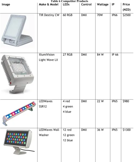
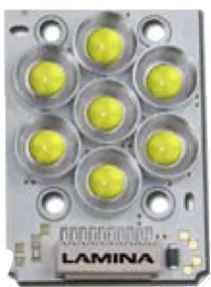
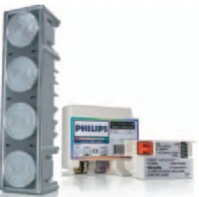
(8) LIST OF TABLES Table 1 UV, visible & IR light and their wavelengths Table 2 CRI guidelines Table 3 Comparison of lamps and lumens Table 4 Comparison of lamps and lumen hours Table 5 Summary of SSL benefits & drawbacks Table 6 Competitor Products Table 1 Component Options Summary Table 8 Philips light level grid (lux) Table 9 Tridonic Atco light level grid (lux) Table 10 Final light level grid (lux) Table 11 Manufacturing quotes for preferred cast option Table 12 Manufacturing quotes for cheaper extruded option Table 13 Cost amortisation for cast oval option (front) Table 14 Cost amortisation for cast oval option (rear) Table 15 Cost amortisation for extruded rectangular option (heatsink) Table 16 Cost amortisation for extruded rectangular option (mount) Table 17 Cost amortisation for extruded rectangular option (frame) Table 18 Bill of Materials for cast option Table 19 Bill of Materials for extruded option. LIST OF FIGURES Figure 1 (From left) the first LED, T1, SMD & High Power Figure 2 LED junction Figure 3 The electromagnetic spectrum Figure 4 SPD of a dichromatic LED (left) and an incandescent lamp Figure 5 Indication of CCT Figure 6 1931 CIE Colour Space Diagram Figure 7 Square Law Dimming Curve Figure 8 Efficacy trends for LED and conventional sources Figure 9 Geometry of fixture mount and wall Figure 10 Diagram for illumination equation Figure 11 Polar plot (parallel mount) Figure 12 Polar plot (angle mount) Figure 13 Light distribution concepts 1, 2 and 3 Figure 14 Lamina Atlas Figure 15 Lamina TitanTurbo Figure 16 Lamina LED with heat sink & optic Figure 17 Talex Eos LED and lens Figure 18 Philips LED Module Figure 19 Lexel LX-1000 Figure 20 Philips light distribution Figure 21 Philips Modules and test board Figure 22 Illuminance testing wall Figure 23 Talex light distribution Figure 24 Talex LEDs and test board Figure 25 LED mounting geometry Figure 26 Talex system block diagram Figure 27 (Left to right) DALI USB, DALI Power Supply & RGB Converter Figure 28 LEDs, mounting plate and heatsink Figure 29 SolidWorks model of prototype Figure 30 Machined prototype Figure 31 Mounting & wiring detail Figure 32 Production option 1: oval profile Figure 33 Production option 2: rectangular profile Figure 34 Temperature testing results Figure 35 Correlated Colour Temperatures of 3900K (left) and 7500K Figure 36 Theoretical colour gamut.
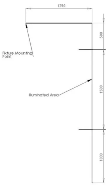
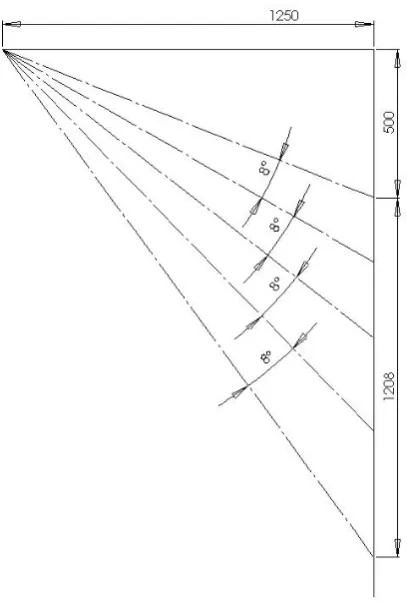
(9) Figure 37 Primary colour illumination (red, green blue) Figure 38 Mixed primary colours (yellow, purple, light blue) Figure 39 Developed Product - 1.25m setback, 29° optics, 25W.
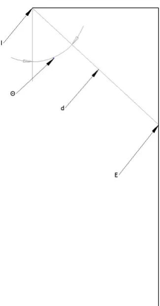
(10) 1 INTRODUCTION 1.1. Background of Study. As the world population continues to expand and develop, the pressure on our remaining resources rises with it. Achieving energy savings in any possible way is something that is destined to become increasingly vital in the future. Lighting consumes more energy than is often appreciated, around 19% of electricity produced worldwide is used purely for our lighting needs (Belshe & Kinney, 2006). The cost involved, both financially and in terms of carbon emissions, means any improvements are worth investigating. Moreover, finding ways to improve the everyday experience of people at work is significant for human productivity, enjoyment and wellbeing. Light emitting diodes (LEDs) are the next generation of lighting, and are set to become superior to conventional sources both in terms of performance and human benefit in the near future (Serpengüzel, 2003). While this fundamental change will not happen overnight, LEDs are beginning to find uses in niche applications. Promoting their use in these niches will help to bring in Solid State Lighting (SSL refers to the use of LEDs for illumination, as opposed to indication) as the new standard light source in the future. Generally, artificial light is considered by most people to simply be a necessary tool to help complete tasks and make the useful day longer. Rather than being a simple appliance, light has more of an effect on humans than it is often given credit for. There are three main ways in which light influences behaviour, the most obvious being as an aid to complete visual tasks. Light also has a perceptual effect, giving an impression of the environment and affecting motivation and contentment. Finally the illuminance, spectral content and duration of the light controls our circadian pattern and the wake/sleep cycle (Duffy & Wright, 2005). 1.2. Statement of the Problem. This leads to the motivation for this project. The aim for the literature review was to understand the background, benefits and peculiarities of LEDs in lighting applications. The review covers the use of SSL in a general illumination sense, Page | 1.
(11) with some of the information gathered used for the more specific architectural lighting application. Following this, the applied side of the project aimed to take this knowledge and develop a practical, working LED product for the architectural lighting market. More specifically, there was a need to research the reasons why LEDs are yet be widely accepted as a source of general illumination, and what can be done to overcome the problems. It also looks at the history, other uses and future potential of LEDs. The development of the working prototype included designing, building and large scale manufacturing methods and potential. The prototype was also used for testing and measurement of cooling ability, white light and colour range, intensity, power consumption and light intensity distribution.. Page | 2.
(12) 2 RESEARCH INTO LEDs, THEIR CHARACTERISTICS AND MARKETS 2.1. State of the Art 2.1.1 Specific questions that guided the research. The principle reason for the research was to find why LEDs are largely yet to be accepted as replacements for traditional lighting, despite the benefits they promise. Secondary to this was to understand the performance differences between LED and traditional sources in terms of spectral distribution, colour production and operating requirements. To help guide the research the following questions were proposed: -. What are the benefits to the end user that will make the high initial cost of Solid State Lighting systems more acceptable? How can consumers be convinced of these benefits and what effects do these benefits have on enjoyment, productivity, and visual perception?. -. Solid State Lighting has the potential to save vast amounts of electricity through lower power consumption and efficiency, reducing carbon emissions. What is being done to promote Solid State Lighting research and what are the problems it faces?. -. Many aspects of SSL are much different to traditional lighting (spectral output, power requirements, thermal management, lifetime etc). What do these differences mean for the design of lighting products? How can the benefits of SSL be enhanced by the design of the products?. 2.1.2 Brief History and Development Lighting technology can be grouped into three main areas; initially it was fire based (candles and lanterns), followed by vacuum tubes (incandescent and fluorescent) and gas discharge (Mercury and Sodium) and now semiconductors (LEDs) (Serpengüzel, 2003). While there were overlaps with the development of Page | 3.
(13) the different technologies, there is no doubt LEDs are the most modern. The principle behind them was first seen back in 1907, when a yellow glow was observed coming from a silicon carbide (SiC) crystal when an electric current was applied. However, the first practical, visible light emitting diodes were developed in 1962, based on gallium arsenide phosphide (GaAsP), which gave a red emission (Holonyak & Bevacqua, 1962). The measure of the ability of a light source to convert energy into light is called the “efficacy”. This is measured in lumens of light output per watts of input electrical power (Ian Ashdown, 2006). Essentially, this gives the portion of input energy that is converted to visible light and not lost as heat or non visible radiation. The early LED described above only had an efficacy of around 0.15lm/W, but found use as an indicator in control panels and similar applications (Steranka et al., 2002). Throughout the 1970’s and 80’s, the efficacy improved and a new compound; aluminium gallium indium phosphide (AlGaInP), allowed orange and yellow LEDs to be produced. Red LEDs still had the highest output however, which explains their dominance of the indicator market. They also began to be used for centre stop lights on vehicles in the late 1980’s. Efficacy had increased to around 10lm/W by this time. In the early 1990’s gallium nitride (GaN) LEDs emerged and allowed blue, green and, importantly, white. The flux (light emitted by a source) output of red LEDs had also increased to the point where they began to be used as principle automotive brake lights and single colour signs. The user still needed to look directly at the LED to see the light however, rather than the intensity being high enough for illumination purposes. Efficacy exceeded 20lm/W during the late 1990’s. Since their beginnings in the early 1960’s, the efficacy of indicator LEDs had been approximately increasing by a multiple of 10 per decade. A diverging point came in the late 1990’s when high power LEDs suitable for illumination (as opposed to indication) were developed. These formed a separate product market to the traditional signal LED. Up until this time LEDs were typically packaged in the “T1” style or surface mount (SMD) housings suitable for mounting in signal applications and on printed circuit boards. The new “high power” illumination LEDs, most Page | 4.
(14) notably the Luxeon range from LumiLEDs, required new packaging due to the heat produced. The fundamental LED developments are illustrated in Figure 1.. Figure 1 (From left) the first LED, T1, SMD & High Power. The Luxeon became somewhat of an industry benchmark and other manufacturers quickly produced similar products, and LumiLEDs also improved the design by reducing the thermal resistance, allowing higher input power and flux output. Now there are a number of these high power LEDs on the market from manufacturers such as Osram and Cree. In addition, systems become available that combined LEDs, heat sink and drivers, making them suitable for integration into lighting products.. 2.1.3 LED Operation The core of an LED is the semiconductor chip; this has two regions, where they meet is known as the junction. The ‘p’ region is dominated by positive charges while the ‘n’ is negative; this creates holes and electrons respectively. A voltage across the junction causes the electrons to recombine with the holes and release energy as photons of light (Shur & Zukauskas, 2005). This is shown in simple terms in Figure 2. This energy requirement is equal to the “band gap” energy; in semiconductors such as LEDs, the conduction band contains mobile charge carriers, while the valance band contains electrons bound to atoms. The band gap energy is that necessary to move an electron up a band. This band gap energy varies with temperature and current (S. Muthu, F. J. Schuurmans, & M. D. Pashley, 2002a).. Page | 5.
(15) a Figure 2 LED junction. Both the chromaticity (essentially colour) and intensity of the LED are determined by the material composition of the semiconductor. Aluminium Gallium Arsenide (AlGaAs) gives red, Indium Gallium Aluminium (InGaAlP) gives yellow and green, and Aluminium Gallium Nitrade (InGaN) produces blue and green. This covers much of the colour spectrum and the materials can be fine tuned to give the intermediate colours. Interestingly this principle is essentially the opposite of a photovoltaic cell (solar panel), a semiconductor which converts the incoming light into a voltage. Somewhat ironically, these two technologies are often used in conjunction.. 2.1.4 The Electromagnetic Spectrum Collectively, light emitting diodes are able to produce light in all visible regions of the electromagnetic spectrum (shown in Figure 3), and on into the infra red and ultra violet regions. However, they are narrow band sources; each LED can only produce light or electromagnetic radiation (the more correct term for IR and UV) at its particular peak wavelength and perhaps 25nm either side of this value. The specific colours and their corresponding wavelengths are given in Table 1. This is in contrast to traditional sources that produce light over much of the visible region. The sun produces light over the entire visible region and the ultra violet and infrared regions; this is known as a blackbody radiator. Despite this, some wavelengths are absorbed or scattered by the atmosphere depending on the time Page | 6.
(16) of day, giving the different sunlight shades we see. The inability of LEDs to produce light covering the entire spectrum has implications for the quality of the emitted light and is discussed next.. Figure 3 The electromagnetic spectrum Table 1 UV, visible & IR light and their wavelengths Wavelength (nm) Colour UV. < 390. Violet. 390 – 455. Blue. 455 – 490. Cyan. 490 – 515. Green. 515 – 570. Yellow. 570 – 600. Orange. 600 – 625. Red. 625 - 720. Infrared. > 720. 2.1.5 White & Coloured Light Generation from LEDs Our perceived colour of an illuminated area depends on the Spectral Power Distribution (SPD) of the incident light (S. Muthu, F. J. P. Schuurmans, & M. D. Pashley, 2002b). The SPD is the range and strengths of different wavelengths emitted by a light source. Figure 4 shows an example; light from a mix of two LEDs, and an incandescent source. The latter, with an SPD covering the entire. Page | 7.
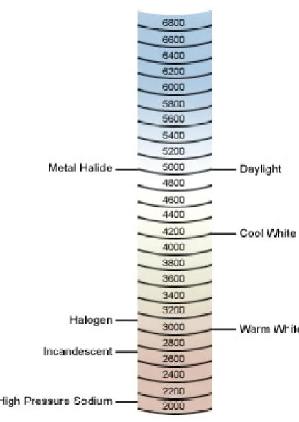
(17) spectrum gives good quality light and renders the colour of objects it illuminates very accurately (meaning they appear very close to their “true” colour).. Figure 4 SPD of a dichromatic LED (left) and an incandescent lamp. Ideally, all artificial light sources will emit light covering the entire spectrum, making them similar to natural light in terms of quality, colour rendering and human enjoyment. This is not always the case, but the more of the spectrum that is produced the better the colour rendering will be. The Correlated Colour Temperature (CCT) also becomes relevant here; this is a measure of the temperature of white light in degrees Kelvin. This measure is based on the output of a “black body radiator”; this is an object that emits a light spectrum that varies with temperature, such as the sun. Increasing temperature produces shorter wavelengths until white light is achieved. Slight variations are the basis for the CCT scale. This can range from reddish “warm” white with a value of around 2500K, to blue “cool” white at around 6000K (Yoshi Ohno, 2006). An indication of the CCT is given in Figure 5. This varying white light can be also be seen in examples such as very warm late afternoon sun and the much cooler fluorescent lighting often seen in hospital operating theatres or dental surgeries.. Page | 8.
(18) Figure 5 Indication of CCT. It is not currently possible to produce white light from a single LED, so instead several methods are used. One is phosphor conversion, where a coloured phosphor coating is used with a different colour LED to give white light. Polychromatic methods mix light from different coloured LEDs to give white. Schubert et al. (2006) gave the basic combinations to achieve acceptable white light: Phosphor Conversion: -. blue LED with a yellow phosphor coating. -. near ultra violet LED with red, green and blue phosphor coatings. Polychromatic: -. blue and yellow LEDs (dichromatic). -. red, green and blue LEDs (trichromatic). -. red, green, blue and amber LEDs (tetrachromatic). Page | 9.
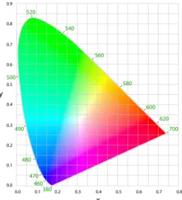
(19) Phosphor conversion allows cheap and simple white light with only one power source, although the efficiency is not as high as the polychromatic approach. The chromacity is also fixed at the time of manufacture, and is difficult to control accurately (Steranka, et al., 2002). Sheu et al. (2003) also compared the two phosphor conversion methods and found the UV approach to be more optically stable. As mentioned, traditional sources produce colour from all regions of the visible spectrum, and hence are combining many colours to produce white light. LEDs produce light in peaks so must take advantage of the human eyes’ ability to only perceive the primary colours and combinations thereof. The emergence of tetrachromatic (RGBA) LEDs was in response to this problem, and aims to “cover” a greater proportion of the visible spectrum than trichromatic (RGB) sources, and therefore provide a better perceived quality of light. Unfortunately, a greater number of chips involved gives a greater reduction in efficacy. Schubert et al. (2006) reported upper limits of 400lm/W, 300lm/W and 275lm/W for dichromatic, trichromatic and tetrachromatic sources respectively. At the current time it is accepted that using two colours to create white gives very low colour rendering but with good efficacy, three colours give reasonable values for both, and four colours have excellent rendering but lower efficacy. Five or more colours tends to give negligible increases in colour rendering but increases the complexity and cost (Zukauskas, Vaicekauskas, Ivanauskas, Gaska, & Shur, 2002). Crucially, this polychromatic approach also allows the CCT of the white to be varied, and produce an immense range of other colours, provided each individual LED can be properly controlled. The limits of this are defined by the particular colours of the LEDs used, and is discussed next. In 1931 the Commission Internationale de l´Eclairage, (International Commission on Illumination or CIE) devised the colour space diagram, which equates colour to an (x, y) coordinate system. A third value (Y) gives the luminance of each colour. Although the diagram was updated in 1960 and again in 1976 to give a more uniform colour variation, the 1931 edition is still widely used. Figure 6 shows this Page | 10.
(20) diagram and also includes the approximate wavelengths of the colours at the perimeter in green text.. Figure 6 1931 CIE Colour Space Diagram. In a polychromatic LED system, the coordinates of each LED can be plotted on this diagram, and the area between the points represents the range of colours achievable with that LED system (Ries, Leike, & Muschaweck, 2004). It follows that with two LEDs, only a straight line is given and poor colour rendering is achieved. For the RGB approach, the three LED points cover a triangular area, while RGBA gives a quadrilateral, and so on. This range of colours possible is known as the colour gamut. The greater the number of different colour LEDs used, the greater the colour gamut and colour quality possible, although the law of diminishing returns applies. The particular wavelengths of the colours used in a polychromatic system of LEDs have an impact on the colours gamut, the colour rendering and the efficacy, so they must be carefully chosen.. Page | 11.
(21) 2.1.6 Colour Rendering Index and Colour Mixing The Colour Rendering Index (CRI) is the current standard measure of the colour rendering ability of light sources. The values range from below 40 for poor quality lighting (such as the low pressure sodium used in street lighting), to 100 for natural midday sunlight. This is why colours appear “washed out” or simply wrong under street lighting. Conversely, much more accurate perception of colour is possible under sunlight. Perfect colour rendering sources are considered to be an incandescent lamp for warm white sources and natural daylight for cool white (B. G. Ashdown et al., 2004). In simple terms, the process to determine the CRI is first to match the CCT of the test light source to that of a reference light source. In turn, the test and reference sources are used to illuminate 14 standard colour samples. Of these samples, some are highly saturated and others are of a medium saturation, while skin and leaf tones are also included. The difference in perceived colour between the test and reference light sources on each sample is calculated using the 1964 CIE colour space diagram. This gives 14 values, but generally only the average is stated, this is the CRI (Yoshi Ohno, 2006). A high CRI theoretically indicates better colour rendering, with 100 being the maximum. Values of around 85 are generally given for trichromatic LED sources, and around 90 for tetrachromatic. The approximate CRI requirements for different situations have been given by Muthu et al. (2002b) and are shown in Table 2. Indoor retail space is considered the most demanding as consumers need to have the best possible appreciation of the appearance of products. Table 2 CRI guidelines CRI Situation. Page | 12. Indoor retail space. >90. Indoor office or home. 80. Indoor work space. 60. Outdoor pedestrian area. 60. General outdoor lighting. 40.
(22) Even though it continues to be in widespread use, work by Bodrogi et al. (2004), Sándor & Schanda (2005) and Ohno (2004b) and others has shown that the CRI does not give an accurate representation of colour rendering for LED sources. (Narendran & Deng, 2002) even found that the perception of colour quality increases as CRI decreases and that, for LEDs, RGB sources are preferred. One contributing factor to this problem is that the 1964 colour space diagram is highly non uniform and is now obsolete, but is still the basis for the calculation. Also, as the CRI is only the average of measured colour differences, the source may be poor at rendering colours needed for its particular application, but still have a reasonable CRI. Another problem is that the CRI only measures the absolute colour difference between the test and reference sources, and does not take into account the direction the difference is in. A higher chromacity will increase clarity, while a lower one will reduce clarity. Finally, the 14 colour samples do not cover enough of the colour spectrum (Wendy & Yoshi, 2005). There is now a consensus that a new metric is needed. Although it is widely used elsewhere, Philips does not list the CRI for its products in datasheets. Instead it states that the CRI is “not measurable” and directs readers to a 1995 International Commission of Illumination (CIE) paper entitled “Method of Measuring and Specifying Colour Rendering Properties of Light Sources”. A replacement for the CRI specifically for LEDs is needed. One possibility under consideration is the Colour Quality Scale (CQS). This uses some of the same colour samples as the CRI, but bases the calculations on the improved 1976 l*a*b* colour space rather than the 1964 version. An increase in chromacity is not penalized, as this often increases clarity, the CRI does not recognise this. Extremely high or low CCT also has a negative effect on colour rendering, unlike the CRI the CQS takes this into account. The final difference is that the CQS uses the root mean square of the colour differences rather than just the average like the CRI does. This helps to make the effect of one large colour difference obvious in the final CQS score, while the CRI approach can hide such a variation. The colour gamut, discussed earlier, is beginning to be used as an indication of colour rendering ability, as a wide range of possible colours also gives a good spectral content.. Page | 13.
(23) Nevertheless, there has been intense interest in maximising the measured CRI while maintaining an acceptable efficacy; this is a balancing act as these two properties are in a trade off relationship. The fundamental reason for this is that the potential luminous efficacy is highest with a single colour light source at 555nm (green) as this is where the human eye is most sensitive, while the CRI is maximised with light that covers the entire visible spectrum (Y. Ohno, 2004a). The CRI is generally considered to be the more important of the two, as this lags behind conventional lighting sources while the efficacy is comparable or ahead, so it is given preference. Also, lower intensity is needed to achieve comparable perception of brightness if the CRI is higher. Research into the areas discussed next became useful for the development section of the project. In a polychromatic white LED the wavelengths and the number of colours used (RGB, RGBA etc) have an effect on the CRI. Optimised setups are well known, an example for a RGBA setup given by Lei et al. (2007) is 460nm, 525nm, 590nm, 640nm, which gives a CRI of 95 and 306lm/W. The red wavelength in particular has the most impact on CRI and efficacy, although this is more of a problem for RGB than RGBA. In addition, to optimize the CRI of white light unequal proportions of each wavelength are needed. Gaines (2006) has published some thorough research in this area. With target CCT’s of 3500k and 7000k and two different sets of peak wavelengths, the proportion of each colour that maximise the CRI for an RGBA approach is given in the above study. Unfortunately similar information for an RGB approach is not provided. Further, the physical layout of 16 RGB or RGBA LEDs in a four by four array that maximise the CRI are given. One possibility related to this work is to use the suggested proportions of each colour as a guide to the actual number of each colour LED required. They can then be driven at a constant intensity. In doing this, the optimal layout would need to be researched, as those given use a different quantity of LEDs. The uniformity of such an approach would also need to be analysed. The benefit of this being successful is a simplification of the control system. Page | 14.
(24) One of the most important aspects of using solid state lighting is achieving an even and full mix of the different colours used, whether they are mixed to give just white or complete variable colour light. Without careful consideration, the illumination can appear to have a graduation of colour, or a “striped” effect. This is an area of intense interest as it directly as this striping will immediately discourage consumers, and as such is fairly guarded in the literature. 2.1.7 Binning to Reduce LED Variability As high power LED manufacture is still a relatively new industry and as the LED substrates are actually grown, the production process is not entirely predictable. This leads to the number of holes and electrons in a substrate varying, not helped by impurities in the materials used. Because of this, the quality of LEDs varies and can result in different characteristics for the same model of LED. Even two LEDs grown and processed side by side can have different values. The variations include lifetime, chromacity, viewing angle, voltage drop, temperature dependency and intensity. When these LEDs are used in light fittings it can result in unacceptable variations in performance. To help overcome this problem manufacturers group the LEDs, usually by peak wavelength or intensity. This is known as binning and the more accurate the bin the higher the cost to the purchaser. In lighting products the variation problem can also be largely controlled by incorporating a feedback loop into the control system, discussed next.. 2.1.8 Drivers & Control of LEDs There are two protocols by which stage and effect lighting is controlled; DMX and DALI. The older of the two, DMX is widely used and reliable, but is unidirectional. This means it can only send commands to a fixture; it cannot receive error messages from them. DALI (Digital Addressable Lighting Control) is a newer system that is bidirectional but has a lower maximum cable length than DMX. The DALI system has a further advantage in that its wiring requirements are much less strict.. Page | 15.
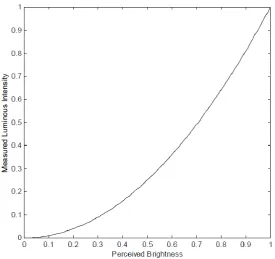
(25) On a more basic level, there are two ways to drive LEDs; constant current and constant voltage. Rubinstein (2007) researched current drivers for LEDs. The constant current system simply uses the mains alternating current and converts it to 350mA to drive non dimming LEDs. In a dimming application, a constant voltage supply is used between the AC input and 350mA converter. The dimming is controlled with a low voltage signal to the converter. In a constant voltage system, which is often used for RGB LEDs, the AC supply is first converted to DC. This low voltage is then split and maintained across the 3 channels, which are each varied by potentiometers or voltage controllers. This approach uses pulse width modulation to control dimming, discussed next. Another important aspect to the control of LED lighting is the dimming; this is handled in a similar way to conventional fluorescent light sources. One of two methods is used; the first, constant current reduction, is self explanatory. The second is pulse width modulation. This is where the LED is strobed on and off at a frequency of several thousand hertz. It is the ratio of 0% and 100% output that gives the dimming, as the human eye perceives the extremely fast strobing as different levels of brightness. Another phenomenon associated with dimming is the non linear response of the human eye. Essentially this means that increasing the intensity of a light source by, for example, 50% will not make it appear 50% brighter to the human eye. Figure 7 shows the relationship between intensity and perceived brightness, known as the “square law” dimming curve (Robinson & Ashdown, 2006). While most controllers take this into account, it shows again the subjective nature of many aspects of lighting.. Page | 16.
(26) Figure 7 Square Law Dimming Curve. Consumers place great importance on adjacent lighting products appearing to have the same colour temperature, chromacity and intensity. All of these parameters change with junction temperature, lifetime, and from LED to LED, even with accurate binning. The minimum perceptible colour difference (MPCD) can be calculated but a guide is a value of 50K to 100K near 4000K CCT (Muthu, et al., 2002a). This is a small amount so a method to maintain the colour point is necessary if binning is less accurate. A feedback loop is often used to maintain the emitted light as there are many factors that affect the light output, junction temperature being the most obvious. Complicating this is the different responses of each colour to temperature. Amber LEDs decrease in efficiency by 80% over a temperature range of 25oC to 120oC, while blue and green lose from 5% to 35% efficiency (Ian Ashdown, 2006). Furthermore, LEDs degrade at different rates, white and green wear faster than blue or red. The junction current also affects the light output parameters. As current increases the chromacity shifts to a shorter wavelength, while the shift for red is small, blue and green are much higher. This is alleviated somewhat by the fact that Page | 17.
(27) increasing junction temperature results in longer wavelengths, although there is still variability (Muthu, et al., 2002a). Monitoring these variables and adjusting the drive current to suit can be achieved in two ways: The simplest method involves measuring the temperature of the heat sink and using this to estimate the temperature of the junction. The junction temperature then gives the approximate colour point. The graphs of heat sink temperature versus junction temperature, and of junction temperature versus colour point, must be accurately known. These can be tested in a lab situation for each model of LED used, but there is still uncertainty with this method. The more accurate way to control the output is to use a colour sensor to measure the colour directly in terms of its coordinates on the CIE colour space. This of course is more expensive due to the sensors needed, and a portion of the light is blocked and lost by it, but it is much more accurate (Man & Ashdown, 2006). Regardless of which method is used, it will require the drive current to be gradually increased over the life of the LED as it degrades, to maintain intensity. This leads to further degradation, exacerbating the problem. Long life is still achievable, but it is less than if the LEDs are driven at a constant current and the intensity gradually declines. These systems allow some sort of end of life warning feature to be built in; one approach used is to run the LEDs at 100% up until the final 10 hours, where they operate at 50% intensity. The life claimed by LED manufacturers should not be taken as a guarantee, testing within the proposed fitting should be carried out as the temperatures will be different.. 2.1.9 Other Applications of LEDs There are five main areas where LEDs are used are; indication, automotive, signage, general illumination and communication (Arik, Petroski, & Weaver, 2002). Easily the largest market is communication, with the backlighting of keypads and LCD screens in mobile phone and other personal electronic devices using about 40% of LEDs produced. Backlighting for signs and video displays represent around 23% Page | 18.
(28) of production, while automotive (brake, signal and interior lighting) uses 18%. Indicator LEDs for traffic lights, electronic products and instrumentation panels use about 14% of total production. Finally, general illumination (architectural/accent, torches, boats and recreational vehicles) makes up 5% of the market (Schanda, 2005). The single colour indication and automotive stop light applications are particularly suited to LEDs as they are much more efficient than filtered incandescent bulbs at producing the needed colour. White applications are slightly less advantaged in this respect. Also worthy of note are LEDs relation; OLEDs, which are made from organic materials. Although development of this type of semiconductor is less advanced than LEDs, they have different properties that will make them suitable for different applications. OLEDs are a much more diffuse light source, and are typically found in a panel form rather than many single light points. As outputs increase, these will find use as screens (with lower power draw and no need for a backlight as with LCD), glowing illumination panels and even flexible displays as they do not need to be rigidly mounted. 2.1.10 Global Lighting Markets & Government Promotion The current global lighting market is dominated by fluorescent, incandescent and HID systems. Market information on LED systems is scarce and propriety, but these conventional sources can aid in understanding the lighting industry. Lighting uses from 5 to 15% of electricity generated in developing countries, and up to a substantial 80% in developing nations, averaging to a global figure of 20% (Bhusal, 2009). This shows how important energy savings through lighting have become. In the developed world, residential lighting practices vary from country to country. In recent years, residential US customers used incandescent for 86% of their lighting, a similar value is used in New Zealand and Australia. Meanwhile, Japan has a much higher proportion of florescent, around 65%. In Russia residential lighting is supplied almost entirely by incandescent. In developing countries, on grid residential lighting is largely fluorescent (off grid is mostly fuel based).. Page | 19.
(29) In commercial buildings lighting is split differently; with developed countries (data is based on OECD members) using fluorescent for three quarters of commercial needs. Notably the US is lower than this average, with around half fluorescent, one third incandescent and the remainder made up by HID. Again, usage varies across the developed world, with American opening hours and therefore lighting requirements being longer than the rest of the OECD. Finally, industrial consumers in developed countries used an average of 62% fluorescent, 37% HID and only 1% other sources (Bhusal, 2009). Although residential lighting is generally the least efficient, its short usage times mean it has low energy use for the size of the building. The opposite is true for fluorescent sources. Efficiency gains can be made in all areas with LEDs, this suggests fluorescent users should be targeted first, i.e. the commercial and industrial sectors. The US Department of Energy (DOE) actively encourages research and development by the industry. With the CALiPER program (Commercially Available LED Product Evaluation and Reporting), whereby LED products are independently performance tested and the results made public. This allows consumers to choose the best products thus creates competition. It also helps promote SSL to consumers. Through meetings with industry experts, the DOE has also established a framework of specific areas of LED research with targets for R&D progress, and a method for prioritising them. This is aimed at research organisations and helps the DOE to allocate funding. The Japanese government introduced the “Akari Project”, an association of 13 business entities and seven universities. This aims to produce a commercial white LED light with 120lm/W by 2010. Taiwan has a similar group of companies. The JLEDS association (Japan LEDs) aims to standardise SSL and promote research in the technology. China is developing four industrial bases related to SSL with support from the government. Page | 20.
(30) Despite the issues faced by the SSL industry, the high brightness LED market as a whole is considerable with a global value of $4 billion (Phillips et al., 2006). The majority of these LEDs are produced in North America, Europe, Korea, Japan and Taiwan. The dominant companies in the lighting industry are Philips, Osram and General Electric, based in the Netherlands, Germany and the United States respectively. In recent years all three have developed partnerships with, or bought, companies specialising in LED development. 2.1.11 Future Growth & Potential An interesting observation with regard to the future of LEDs is that as the efficiency improves and less energy is wasted as heat, less heat sink area will be needed, in turn reducing weight, cost and size. Steel (2007) and Navigant Consulting Inc (2006) forecast the growth of many different aspects of Solid State Lighting. It has been shown that, although the overall market growth for high brightness LEDs (encompassing signals, signs, mobile phones, automotive and illumination) has slowed since 2004, the illumination component has increased. Predictions for the next three years also show a strong increase in LED lighting products, with the world market value expected to increase from $400 million in 2008 to $1 billion in 2011. While the majority of this rise is predicted to come from the increasing performance of white LED lighting products, the RGB market is also set to increase from around $200 million in 2008 to nearly $400 million in 2011. As of 2006 architectural lighting was the largest sector of the LED lighting industry, although general illumination will grow as white LEDs become more cost effective for that application. Of course the main reason behind the expected growth of this displacement technology is the continued rise in life and efficacy, and the drop in price for high power LEDs. Navigant Consulting Inc (2006) gave a summary of the predicted values for life, efficacy and cost for different CRI levels, with extrapolation to 2027. These predictions have been converted to graph form and can be seen in Appendix 1, 2 and 3. Page | 21.
(31) The adjustability of Solid State Lighting makes it appealing for future use. There is the possibility of varying the CRI of a polychromatic LED source to provide enough colour rendering ability for the given situation, and higher efficacy at other times. For example, the system could use low colour rendering for low occupancy or for night time security, with a high CRI for normal use, or other similar schemes. This modulation would increase the overall efficiency of the system and reduce energy use. The system could also switch to red at night to preserve the users’ ability to see in the dark. The possibility of using the fast strobe ability for communication has been suggested by Schubert & Kim (2005). While invisible infrared light from television remotes are already used for this purpose, the high pulse frequency ability that LEDs offer means visible light could also be used in this way without being noticed by the human eye. This would allow short range communication of systems in a room, an alternative to overcrowded radio waves. Automotive LED head and tail lights could also communicate speed and distance information to other vehicles with no perceivable effect on the light output. There is also the possibility of using LEDs as standby or backup lighting, with fluorescent sources for normal use. This “hybrid” idea is a possible short term use for LEDs until the outputs increase sufficiently and they become cheaper. This concept would also make the technology more palatable to consumers for general illumination and show that it is useful in the meantime. As residential users are generally drawn to the lower purchase cost and compactness of incandescent sources (B. G. Ashdown, et al., 2004), LED “lamps” could be used in the residential retrofit market to replace older technology. This is much like compact fluorescent lamps which are currently replacing incandescent sources. While the major technical hurdle of converting the input power to low voltage in such a small space is a problem, a simple “plug and play” solution would be simple for consumers to adopt. Standardisation of the connectors and controllers would need to be increased for this to be successful. Page | 22.
(32) The low power needs of LEDs make them suitable for remote solar powered applications such as sea beacons, runway lights, general lighting for developing countries lacking infrastructure and so on. The use of LEDs for general illumination in developing countries also has great merit, if SSL is used in areas as they become connected to a national grid, the low efficiency and heavy metals of incandescent and fluorescent sources can be avoided entirely. Consideration has also been given to using LEDs for a lighting system to match our circadian rhythm. The benefits of such a system include more comfort and less stress, although this it is possible these benefits would not be attributed to the lighting type by many people. As their colour and intensity are variable LEDs are very much suited to this application. To be effective, a circadian system should be the main source of general illumination, which is currently too expensive with LEDs. However, there are some reduced light, general illumination applications that may be feasible sooner. One possibility is passenger aircraft interiors, which could benefit greatly with such an approach on long haul flights to reduce jetlag among passengers. The well known LED traits of robustness, compact size and low power consumption are also beneficial in this application. The weight of heatsinks would need to be considered given how strictly weight is monitored in aircraft design. One final intriguing possibility has been suggested by B. G. Ashdown et al. (2004). This involves using a single, invisible UV LED in a room to excite phosphors in special “bases” around a room, causing them to emit white light. This means a single powered source can be used to create light throughout the room via these movable, wireless bases. The only limiting factor is that the UV radiation would need to be kept to a safe level.. 2.2. Current LED Limitations. There are a number of technical areas where LEDs need to develop to become a genuine alternative for traditional lighting technology. These include quantum Page | 23.
(33) efficiency, thermal management, packaging and importantly, consumer acceptance. These issues are discussed next.. 2.2.1 Internal Quantum Efficiency To increase the brightness from each LED, the internal quantum efficiency needs to improve. This relates to the number of holes and electrons that successfully recombine. Currently this stands at around 80% and 50% for red and blue LEDs respectively, while the “green hole” has less than 10% (Yoshi Ohno, 2006). (Conveniently, the green region is where the human eye is most sensitive so light at these wavelengths appears brighter than other regions with the same intensity.) These efficiencies are increasing as the manufacturing process improves and produces fewer defects, and new materials are discovered. This offers insight into the future potential of LEDs, as the quantum efficiency is theoretically 100%.. 2.2.2 Packaging & External Efficiency The packaging of the LED chip is another avenue where improvements can be made and the overall efficacy raised. The optics used to define the shape of the light can cause internal reflections which reduce the light emitted. The necessary electrical contacts do not reflect light well, also hindering the efficiency. Improvements have been made to the substrate material, moving from partially absorbing to fully transparent to allow more light to reach the reflective surfaces. External efficiencies above 50% have been reached for infrared and red radiation/light emitting diodes, if similar levels are reached for LEDs over the whole visible spectrum 150 to 200lm/W is achievable for white light sources (Tsao, 2005). The rate that internal and external efficiencies are improving leads to an interesting trade off suggested by Tsao (2005). The efficiency that improves the most will eventually dictate the type of structure used by LEDs. If external efficiency proves to be highest, large area, lower power density and lower cost per. Page | 24.
(34) area chips will result. The other case is with higher internal efficiency. This will lead to small area, higher power density, low high cost per area chips.. 2.2.3 Heat Management Issues The other major concern that LED makers and lighting designers need to be aware of is the importance of managing the thermal needs of the LED system. The intensity, life and chromacity of LEDs are extremely dependant on the temperature of the chip. While one of the benefits of LEDs is that heat is not used to produce the light (as with incandescent), part of the input power is lost as heat due to inefficiencies. This is a serious problem as junction temperature increases of just 14oC can reduce intensity by 14% for red LEDs, although less for blue and green. The life of the LED is also reduced by 10% for every 10oC increase in temperature above the recommended maximum (I. Ashdown, 2002). Heatsinks (either blocks or fins, made from aluminium) are commonly used, with simple convection used to maintain the temperature. Heat pipes are also sometimes used in more complex or compact designs, while more extreme setups use cooling fans, although these can add noise and will increase energy use. The move to larger, “high power” style packaging was partly due to these thermal issues, as the increased chip sizes could now tolerate higher drive currents and heat. The older T1 style package, and especially the electrical contacts, could not. Nevertheless, good heat dissipation is still crucial to an LED system. Another issue here is that the larger the chip the more light is absorbed by internal reflections and lost. Compromise is a recurring aspect of LED design. The thermal resistance becomes relevant here; this is listed in most LED product literature. This is a measure of how effective the transfer of heat from the junction to the LED mounting surface adjacent to the heatsink. Obviously the lower this value the more input power the LED junction can withstand while maintaining acceptable temperatures.. Page | 25.
(35) 2.2.4 Consumer Acceptance Consumer research regarding specific preferences and demands of SSL is one of the key areas of interest for manufacturers and designers. Accordingly, it is almost always undisclosed to protect the research and investment they are undertaking. However, the Governments of various countries, in particular the United States, are keen to encourage the uptake of LED systems for energy and environmental reasons. To this end, they have released research and recommendations on making LED products as appealing as possible to consumers. Unsurprisingly, these studies inevitably find that the acceptance (or lack thereof) of LED systems is closely related to the cost. In a report prepared for the US Department of Energy, (B. G. Ashdown, et al., 2004) presented the various lighting characteristics and the importance given to them by consumers. The principle attribute found here was cost, in terms of initial purchase price, maintenance and efficiency. The key finding was that residential users are more interested in the initial cost, while commercial consumers are concerned with the total cost (which considers efficiency and replacement frequency). While LEDs currently have a place in niche applications, this and other investigations have shown that most residential consumers are generally not prepared to pay the higher initial cost of LED lighting yet, even though they will recover this cost through longer life and reduced energy use. This suggests that LEDs will find more applications in the commercial sector sooner, as the cost structure is more suited to this area. The colour of the light is also considered important in general illumination. Warm, reddish white light gives a sense of comfort and relaxation, while cooler, more blue light conveys awareness and activity. Further, some colours are perceived better when illuminated by cool white and others by warm white. It has even been reported that people prefer warmer white light in winter and cooler in summer (B. G. Ashdown, et al., 2004).. Page | 26.
(36) In terms of quality of light output, the same study found mixed preferences. While consumers’ value a high quality of light, they are not generally aware or appreciative of the wider benefits of good lighting. It also found that the colour rendering ability of new general illumination sources is critical and should approach that of incandescent bulbs. Consumers do value full, pure colour from light sources. However, in the case of LEDs, the area illuminated may be less atheistically appealing than the emitted light from the LED itself. Complete control of light sources is another feature appreciated by consumers. This includes being able to digitally tune the colour, temperature and dimming so it can be controlled remotely and integrated into other systems. Long life for lighting sources is also highly valued by consumers. This is beneficial both in terms of the cost of replacing lamps/bulbs and the inconvenience of doing so. Although to a lesser extent, the report also found consumers value compactness, safety, durability and low environmental impact for light sources. With the exception of cost and colour rendering, LEDs outperform conventional sources in all of the areas discussed above; suggesting cost is the main factor holding back market penetration. While improvements in manufacturing techniques and increases in production scale are reducing cost continually, the expenditure issue will need to be carefully considered and compensated by additional features and benefits. It has been reported that consumers are generally unaware of the possibility of using LEDs as a general “white” source of illumination, with the perception that they are limited to coloured and novelty applications. The use of LEDs in torches and desk lamps is helping to break this belief, but ways to increase understanding of LED potential are needed. Further, it has been shown that the measures used by engineers and designers to describe and compare performance (CRI, CCT, efficacy and so on) are of little interest to consumers. This suggests that a more qualitative approach be taken to measuring lighting performance with perceptions and “feel” of the light likely to Page | 27.
(37) be a more valuable indicator of preference than the raw numbers. A related observation regarding differing markets by (B. G. Ashdown, et al., 2004) is also relevant. They found that, in very general terms, US consumers tended to over light an area, while European and Asian markets were more aware of the aesthetic benefits possible. Additionally, these latter markets are more likely to consider the light fixtures as a piece of art as opposed to a simple appliance. Convincing commercial users that the benefits of LED systems for general illumination outweigh the purchase cost will need to be tackled as LED output becomes more usable. (B. G. Ashdown, et al., 2004) suggests that the principal benefit that should be made known is the strong positive influence good lighting has on behaviour. LEDs can be controlled to match the human circadian rhythm, making workers more alert and less stressed. The variability also allows interesting effects and atmospheres to be created. These benefits are more appealing to consumers than the technical and engineering qualities the designers and manufactures are concerned with, such as CRI and efficacy. It is clear that initially the commercial market will be more accepting of LED systems, than residential consumers. Part of the reason for this is that this market is more willing to pay a higher initial cost and have lower maintenance and energy consumption. 2.2.5 Health & Safety The low heat and low voltage requirement of LEDs have safety advantages, but there are some dangers to be aware of. There is a recognised “blue light hazard” with any intense light. As shorter wavelengths have more damaging energy, “blue” refers to that general area of the spectrum, as opposed to the red or green regions. Ultraviolet light is absorbed or blocked by the cornea and lens of the eye, but wavelengths around 440nm can reach the retina (Algvere, Marshall, & Seregard, 2006). There has been much research into this problem with regard to lasers, and now the outputs of LEDs have reached the point where they pose a risk. The environmental impact of lighting products should also be considered. In addition to the reduced emissions from lower energy consumption, LEDs also have Page | 28.
(38) less harmful heavy metals. Fluorescent lamps are the main concern here as they contain mercury, making manufacture and disposal more dangerous than with solid state sources. The cost to dispose of a fluorescent lamp safely can actually be higher than the initial purchase cost.. 2.3. Benefits & Drawbacks of Solid State Lighting 2.3.1 Benefits of Solid State Lighting. The principal benefit and main driver for LEDs increasing penetration into the general lighting market is the reduction in energy costs they offer. The fundamental reason for this is that LEDs convert electricity to light directly, while with other sources the light is a by product of other conversion processes. From initial efficacy values of around 0.1lm/W in 1960 for indicator lamps, high power LEDs now achieve over 100lm/W. In comparison, incandescent light bulbs give less than 15lm/W, fluorescent tubes between 60 and 80lm/W and metal halide around 120lm/W. However, as the materials and packaging technology for LEDs are constantly improving, the rate at which LED efficacy is increasing is far greater than other sources. The efficacy trends are illustrated in Figure 8 (Krames et al., 2007). The superiority of LEDs in terms of efficacy is further shown by the theoretical maximums of each source, imposed by fundamental physical reactions. Incandescent lamps are limited to around 17lm/W by the filament temperature. Fluorescent lamps have a maximum of around 90lm/W due to losses converting UV to visible light (Schubert & Kim, 2005). On the other hand, LEDs have theoretical maximum efficacies approaching 400lm/W, although it is lower for multicolour clusters as discussed later. This is because they directly convert electricity into light, rather than heating a filament or exciting a gas first. sarah_wendyclr18.jpg. Page | 29.
(39) Figure 8 Efficacy trends for LED and conventional sources. There was much optimism in the literature in the early 2000’s that the efficacy of LEDs would improve enough to replace fluorescent lamps within the decade. While this does not now appear realistic, the technology has improved greatly and few doubt that it will become the mainstream lighting system in the future. This is where the potential of LEDs is most obvious; the possible reductions in energy use are significant and important as environmental pressure increases. Around 20% of electricity generated globally is consumed simply by lighting, resulting in around worldwide carbon emissions of 2900 million tonnes annually (Singh, Gupta, & Poole, 2008). Guidelines and limits on the lighting power density are already in place and will likely become more stringent in the future. The US Department of Energy roadmap predicts the efficacy of white light LED sources will be 137lm/W by 2015. Although optimistic to the point of being simply hypothetical, a worldwide switch to LEDs by that time would yield energy savings of around 1000 tera watt hours per year. This equates to savings of US$100 billion and a reduction in carbon emissions of about 200 million tons, per year (Krames, et al., 2007). A side benefit is the reduction in heat produced by lighting placing Page | 30.
(40) lower loads on air conditioning systems. Savings of this order are one of the principle motivators for SSL. The other major benefit of LEDs as a light source is the long life they offer. Typical lifetimes are in the region of 100,000 hours, compared to 2000 hours for incandescent and 15,000 for fluorescent. However, as discussed later, the degradation of LEDs over their life means that in practice around 50,000 useful hours is achievable and is the lifetime claimed by most LED makers. As mentioned by (Steranka, et al., 2002), this long life fundamentally changes the way lighting fixtures can be designed as the LED can be expected to outlive the fitting. This removal of the need to access the light source for replacement means the product can be made more compact and aesthetically pleasing. As well as making manufacture cheaper through fewer moving parts, the maintenance cost of a fitting over its life is significantly reduced. It also means that the LEDs and control gear can be manufactured as one unit, easing manufacture and making the device more compact. In addition to the long life of LEDs, as they are a solid state device they are durable and impact resistant, again they are much better than incandescent and fluorescent sources in this respect. As other sources generally emit light in a 360o range, reflectors are needed to direct it, causing light losses and light pollution in some situations. LED offer flexibility in terms of light output pattern; they can range from spot to wash (from 10o to about 120o). LEDs also remove the need to isolate the “bulb” from people to prevent breakage. While they do produce heat, with adequate heatsinking an LED product is much less likely to cause burns than discharge type sources. The preferred correlated colour temperature has been investigated by Scuello (2004) who found that while typical white museum lighting is around 3000K, the participants in his trial believe that 3600K gives the most pleasing appearance. Furthermore, Ashdown (2002) reported that perceived CCT need only be reported in six (non uniform) increments across the white light range, as higher levels of Page | 31.
(41) accuracy are not sufficiently different enough to be justified. This suggests that the issue of CCT is subjective and should be assessed qualitatively in each application. LEDs allow infinitely variable CCT to be built in and therefore give the full range of white colour temperature spectral distributions to suit each situation and audience. LEDs also have no warm up time to achieve a given CCT. Continuing this idea, the use of RGB or RGBA (a mix of red, green, blue and often amber) LEDs allows the full range of colours to be created, as discussed earlier. This has great benefits in the architectural and stage/theatre markets as DALI/DMX control protocols allow each fixture to be identified and the colour changed instantly, remotely and individually. This is a great improvement over conventional sources where filters must be used to change the chromaticity of the light, these filters burn out and must be manually changed to achieve different colours (Gerlach, 2005). Like conventional fluorescent and halogen, dimming of the light output is also possible with the DALI/DMX interface. The light source in a museum or art gallery environment must only emit wavelengths in the visible region of the spectrum and not infrared and particularly not ultra violet, which is more damaging to delicate artwork (Scuello, Abramov, Gordon, Weintraub, & Weintra, 2004). While other sources such as metal halide and tungsten halogen lamps need a filter to block UV radiation, LEDs are free from this as they have such a narrow, controllable emission band. UV can be deliberately added for other applications. This removes the need for additional UV blocking filters and allows more certainty in claiming a “low/no UV source”. It should still be noted that, although to a much lesser extent, all visible light is potentially damaging to art. LEDs are also safer than traditional lighting as they operate on low voltage and are cool to the touch (although heat sinks can become hot). As they are solid state, they are durable with no fragile glass or filaments. Reliability is also a factor in some environments as they can operate at lower ambient temperatures than fluorescent. The compact size of LEDs allows new mounting options as well as reducing ceiling space requirements. Finally, they have less impact on the Page | 32.
(42) environment as, aside from the reduced energy consumption, they also contain fewer heavy metals, particularly mercury. 2.3.2 Drawbacks of Solid State Lighting The principle disadvantage of LEDs used in Solid State Lighting is that, despite their high efficacy, they have a lower light output than conventional sources. Essentially they are not very bright, despite the concentrated point source appearing so. Because of this more LEDs are needed to offer comparable overall light levels, increasing the initial cost. While the total flux of high power LEDs is constantly increasing, they have only recently reached levels that begin to be useful in lighting applications. (Gerlach, 2005) offers the following comparisons between various lamps and their retail dollar per lumen output value, reproduced in Table 3. Table 3 Comparison of lamps and lumens Lamp Technology. Lumens per Dollar. LED. 0.5 to 10. High Intensity Discharge. 250 to 500. Halogen. 500 to 1000. Incandescent. 1000 to 3300. The lumens per dollar can be used to compare different sources and LED will perform poorly at this comparison in the short term. However, when the lumen hours per dollar is calculated, LEDs offer similar value. Although LEDs have a higher initial purchase cost than other sources, there is almost no maintenance costs, and lower energy requirements. Conventional sources have a lower setup cost but need replacement lamps much more frequently. These contrasting cost structures often have a similar total, (Gerlach, 2005) provided this comparison given in Table 4.. Page | 33.
(43) Table 4 Comparison of lamps and lumen hours Lumen Hours per Dollar Lamp Technology LED. 50k to 1000k. High Intensity Discharge. 1000k. Halogen. 200k to 1000k. Incandescent. 100k to 500k. The problem is that convincing consumers that the higher initial outlay is justified by extra features and a similar overall cost can be difficult. Cowling et al. (2008) note that, as realistically priced LED products are not yet capable of replacing fluorescents which are still very efficient, their use should be restricted to accent, emergency and secondary lighting. This is preferable to attempting to use them for general illumination before the technology is sufficiently developed, potentially souring consumers on the technology. This appears to be the general consensus for now. 2.4. Summary of Literature Review. It can be seen that the literature review has allowed the research questions raised earlier to be understood, and is summarised in this section. It has shown that despite all the bold promises of LEDs, their use must be carefully applied to gain the most benefit from their positive features, while minimising the negatives. The first question related to the direct benefits to consumers that SSL offers. Firstly, LED systems offer intangible benefits, such as improved wellbeing and happiness. There is potential for them to replicate the changing colour of sunlight through the day, helping to match the human circadian rhythm, reducing stress and improving concentration. Like fluorescent sources controlled with digital ballasts, energy use can be reduced by monitoring the changing natural light level and adjusting lighting intensity to maintain a set level. For architectural applications they allow highly saturated and easy electronic (rather than mechanical) colour adjustment. They also offer high efficiency, compact size, robustness and long life. With fewer heavy metals they have less environmental. Page | 34.
(44) impact at disposal. In fact the only drawback is the current cost of achieving a usable light output that is comparable with conventional sources. However, the lifetime cost is similar due to the longer life, reduced energy and lack of maintenance needs already mentioned. Promoting the lifetime cost over the initial cost in marketing is crucial, as is the fact that LED lighting products can be “installed and forgotten” with regard to maintenance. The “feel good” benefits mentioned above are also important to help consumers overcome the high setup cost of LEDs. The next question asked of the steps being taken by Government and research organisations to promote LED use in lighting. SSL has been recognised as a key method for the developed world to reduce energy use and has been supported by programmes by the governments of the United States, China, Japan and several European countries. Most of these are partnerships between Universities and the private sector. There are also several programmes in place to educate consumers on the benefits of SSL and give impartial reports on available products. The final aspect questioned was the key differences between LED and conventional lighting and the ramifications for lighting design. There are a number of aspects to this point and it is important take note of the advantages offered, and manage the disadvantages. For example the spectral power distribution is much different, being “peaky” rather than covering a large section of the spectrum. This does mean care is needed to achieve reasonable colour rendering suitable for the application. Similarly, the colour possibilities of LEDs are far superior, with no filters needed. The lack of necessary maintenance means the fitting does not need to be opened to replace lamps. This, and the fact that LEDs are physically small, allows the designer to make the product compact and simple with no hinges or removable panels. This allows the LEDs can be sealed to prevent dust that reduces output. However, LEDs have a much greater need for cooling than conventional sources; the heat sinks will need to be ventilated to allow cooling via convection. Also, while the LEDs themselves are small, the optics needed to direct and mix the light will probably need to be larger. These issues can make the. Page | 35.
(45) product more bulky and unsightly if not designed carefully. A summary of the most important benefits and drawbacks is given in Table 5.. Benefits -. Table 5 Summary of SSL benefits & drawbacks Drawbacks. Commercial consumers attracted to low lifetime. -. Residential consumers put off by the high initial cost. cost (no lamp replacement & less energy use) -. Fewer toxic materials. -. Colour rendering lower than fluorescent. -. Range of colour including white, electronically. -. Intensity lower than fluorescent. controllable -. More design freedom. -. Compact & durable. Page | 36.
Figure
+7

Related documents
Section l.90(d) of the final rules requires each financial institution or creditor that offers or maintains one or more covered accounts to develop and implement a written
They are (1) as the purpose of this study was to identify the reaction of African American students to a culturally relevant (Ladson-Billings, 1992, 1995a, 1995b, 2009) visual tool
Transmitter Connected to Open Tank With Constan Overflow.
Each module includes a basic and a refresher course. NOTE: The Basic course in each module is required to be completed prior to any refresher courses... The IRB requirement
Although all our member centers provide space for various 12 step meetings and other peer to peer recovery supports – recovery centers are not affiliated with any of these groups..
• exclusive leader board ad on registration web site from date of contract through the summit • logo in pre-conference promotional material • Post-event registration lists
While the nature of the Durham Ritual means that the servus Dei trope is the most common form in which esne appears, it also refers to the slaves who summon
