Design and implementation of Internet of Things for home environment : a thesis presented in partial fulfilment of the requirements for the degree of Master of Engineering in Electronics and Computer Systems Engineering at Massey University, Manawatu, New
179
0
0
Full text
(2) Design and Implementation of Internet of Things for Home Environment. A thesis presented in partial fulfilment of the requirements for the degree of Master of Engineering in Electronics and Computer Systems Engineering at Massey University, Manawatu, New Zealand.. Sean Kelly 2013.
(3) Abstract An integrated framework for smart home monitoring towards internet of things based on ZigBee and 6LoWPAN wireless sensor networks is presented. The system was developed to retrofit existing sub systems of wireless technologies in order to reduce cost, and complexity.. The practical. internetworking architecture and the connection procedures for reliable measurement of smart sensors parameters and transmission of sensing data via internet are presented. A ZigBee based sensing system was designed and developed to see the feasibility of the system in home automation for contextual environmental monitoring. The ubiquitous sensing system is based on combination of pervasive distributed sensing units and an information system for data aggregation and analysis. Results related to the home automation parameters and execution of the system running continuously for long durations is encouraging. The prototype system (ZigBee based) was tested to generate real-time graphical information rather than using a simulator or a test bed scenario. A trail has also been performed with 6LoWPAN technology to provide functionality as the ZigBee based system. The overall internetworking architecture describes the integration of a low power consumption wireless sensor network with the internet. The proposed prototype has advantages in terms of low cost, flexibility of usage. The design of the integrated framework provides a template for other applications related to the Internet of Things.. pg. i.
(4) Acknowledgements I would like to thank my family for supporting me during my course of study. I would like to thank my supervisor Prof. Subhas Mukhopadhyay for his patience and support. I would like to thank Nagender Suryadevara for his technical help and support.. pg. ii.
(5) Abstract .................................................................................................................................................... i Acknowledgements................................................................................................................................. ii List of Figures ....................................................................................................................................... viii List of Tables ......................................................................................................................................... xiii 1. Introduction .................................................................................................................................... 1 1.1. 2. Outline of Thesis ..................................................................................................................... 1. Literature Review ............................................................................................................................ 3 2.1. Wireless Sensor Networks integrated with Internet of Things ............................................... 3. 2.2. Existing Internet of Things Systems......................................................................................... 4. 2.3. Home Automation through Internet of Things ....................................................................... 5. 2.3.1. Existing Wireless Technologies used for Home Automation ........................................... 6. 2.3.2. Existing Wireless Sensor Network Architectures for Home Automation ........................ 6. 3. Contribution to the topic .............................................................................................................. 11. 4. System Structure ........................................................................................................................... 12 4.1. Introduction .......................................................................................................................... 12. 4.1.1 4.2. Integrated Platform for IoT ........................................................................................... 13. Smart sensors requirements ................................................................................................. 13. 4.2.1. Signal conditioning ........................................................................................................ 14. 4.2.2. Signal Input and Output Processing .............................................................................. 15. 4.2.3. Network communication .............................................................................................. 15. 4.3. XBee Structure ...................................................................................................................... 16. 4.3.1. XBee Stack Specifications .............................................................................................. 16. 4.3.2. XBee Topologies ............................................................................................................ 17. 4.3.3. XBee Hardware Specification ........................................................................................ 18. 4.3.4. IoT adaptation ............................................................................................................... 19. 4.4. 6LoWPAN Structure............................................................................................................... 19. 4.4.1. 6LoWPAN Stack Requirements...................................................................................... 20. 4.4.2. 6LoWPAN Topologies .................................................................................................... 21. pg. iii.
(6) 4.4.3. 6LoWPAN Hardware Specifications ............................................................................... 21. 4.4.4. 6LoWPAN Hardware Options ........................................................................................ 22. 4.5. 4.5.1. Gateway Hardware ........................................................................................................ 22. 4.5.2. WSN Interface ............................................................................................................... 23. 4.5.3. IoT communication ....................................................................................................... 23. 4.6. IoT Server .............................................................................................................................. 23. 4.6.1. Minimum requirements ................................................................................................ 24. 4.6.2. Network connectivity .................................................................................................... 24. 4.6.3. Data Reception, Storage and Web server ..................................................................... 24. 4.7 5. IoT Gateway .......................................................................................................................... 22. Summary ............................................................................................................................... 24. Implementation ............................................................................................................................ 26 5.1. Software Development Environment.................................................................................... 26. 5.1.1. Code Composer Studio Setup – 6LoWPAN Module ...................................................... 26. 5.1.1.1. Obtaining and installing Code Composer Studio ...................................................... 26. 5.1.1.2. Project creation for CC430 ........................................................................................ 26. 5.1.1.3. Debugging a CC430 Project ....................................................................................... 28. 5.1.2 5.1.2.1. OpenWRT Toolchain with Eclipse IDE ........................................................................... 31 Windows OpenWRT Toolchain Setup........................................................................ 32. 5.1.2.1.1 Cygwin Installation .............................................................................................. 32 5.1.2.1.2 Windows configuration ....................................................................................... 34 5.1.2.1.3 OpenWRT tool chain compilation ....................................................................... 36 5.1.2.2. Eclipse ....................................................................................................................... 38. 5.1.2.2.1 Required directories from the OpenWRT toolchain ........................................... 38 5.1.2.2.2 Eclipse Setup for Windows/Linux........................................................................ 38 5.1.2.2.3 Eclipse Project Creation ...................................................................................... 39 5.1.2.2.4 Eclipse Remote Debugging.................................................................................. 42 5.1.3. Visual Studio Setup ....................................................................................................... 51. pg. iv.
(7) 5.2. 5.1.3.1. Installation................................................................................................................. 51. 5.1.3.2. Project Creation ........................................................................................................ 51. 5.1.3.3. Project Debugging ..................................................................................................... 54. Software Configuration ......................................................................................................... 55. 5.2.1 5.2.1.1. WAMP Installation..................................................................................................... 55. 5.2.1.2. WAMP Configuration ................................................................................................ 55. 5.2.2. Open source embedded Linux installation ................................................................... 57. 5.2.2.1. OpenWRT Compilation.............................................................................................. 57. 5.2.2.2. OpenWRT installation ............................................................................................... 59. 5.2.3. OpenVPN ....................................................................................................................... 63. 5.2.3.1. OpenVPN Installation ................................................................................................ 63. 5.2.3.2. OpenVPN Certificate and Key Generation ................................................................ 64. 5.2.3.3. OpenVPN Server Configuration................................................................................. 68. 5.2.3.4. OpenVPN Client Configuration .................................................................................. 71. 5.2.4. 5.3. Windows Apache MySQL and PHP (WAMP) ................................................................. 55. XBee Configuration ....................................................................................................... 74. 5.2.4.1. XBee Configuration Software .................................................................................... 75. 5.2.4.2. XBee Coordinator Configuration ............................................................................... 76. 5.2.4.3. XBee End Device Configuration ................................................................................. 79. Network Interface Implementation Techniques ................................................................... 82. 5.3.1. Tunnel Driver Interface.................................................................................................. 82. 5.3.2. Parsing raw data from buffers ....................................................................................... 83. 5.4. 5.3.2.1. Host and network byte order .................................................................................... 83. 5.3.2.2. XMacro technique ..................................................................................................... 85. 5.3.2.3. XStruct technique ...................................................................................................... 87. ZigBee IoT Platform Implementation .................................................................................... 91. 5.4.1 5.4.1.1. ZigBee Hardware Implementation ................................................................................ 91 XBee Gateway ........................................................................................................... 92. pg. v.
(8) 5.4.1.2. XBee Temperature Sensor Module ........................................................................... 96. 5.4.1.3. XBee Hot Water System Monitor .............................................................................. 98. 5.4.2. Address Translation ..................................................................................................... 109. 5.4.3. IPv6 UDP Encapsulation .............................................................................................. 110. 5.4.4. Software implementation on IoT Gateway for XBee................................................... 114. 5.4.4.1. Initialise Serial and Tunnel ...................................................................................... 115. 5.4.4.2. Select from Tunnel and Serial ................................................................................. 116. 5.4.4.3. Processing Tunnel Data ........................................................................................... 118. 5.4.4.4. Serial Has Data ........................................................................................................ 120. 5.4.5 5.5. 6LoWPAN IoT Platform Implementation ............................................................................. 125. 5.5.1. 6LoWPAN Development Hardware ............................................................................. 126. 5.5.1.1. 6LoWPAN Node ....................................................................................................... 126. 5.5.1.2. 6LoWPAN Gateway.................................................................................................. 127. 5.5.2. 6LoWPAN Node Firmware Implementation ................................................................ 129. 5.5.2.1. 6LoWPAN stack ....................................................................................................... 129. 5.5.2.2. Microcontroller Radio Interface for 6LoWPAN stack .............................................. 131. 5.5.2.3. Application to acquire and send sensor data using 6LoWPAN ............................... 135. 5.5.3. 5.6. ZigBee IoT Platform Summary..................................................................................... 125. 6LoWPAN Gateway Implementation........................................................................... 135. 5.5.3.1. Radio interface for 6LoWPAN gateway ................................................................... 135. 5.5.3.2. Software for 6LoWPAN Gateway............................................................................. 136. IoT Server Implementation ................................................................................................. 136. 5.6.1. Sensor Data Acquisition and Storage .......................................................................... 136. 5.6.1.1. Receiving Sensor Samples ....................................................................................... 136. 5.6.1.2. Storing Sensor Samples ........................................................................................... 137. 5.6.2. Graphical Web Interface ............................................................................................. 137. 5.6.2.1. Retrieving Sensor Samples from Database ............................................................. 137. 5.6.2.2. Plotting Retrieved Sensor Samples in Graph........................................................... 138. pg. vi.
(9) 5.6.2.3 5.7 6. Controlling WSN Nodes ........................................................................................... 138. Summary ............................................................................................................................. 138. Experimental Results................................................................................................................... 140 6.1. Fabricated Sensor Modules for monitoring the Smart Home ............................................. 140. 6.2. Efficient mechanism for sensor data storage ...................................................................... 145. 6.3. Quality of Service parameters for XBee IoT Platform ......................................................... 146. 6.3.1. Reliability ..................................................................................................................... 146. 6.3.2. Throughput ................................................................................................................. 147. 6.3.3. Jitter ............................................................................................................................ 149. 7. Conclusion ................................................................................................................................... 150. 8. Challenges and Opportunities..................................................................................................... 151 8.1. 9 10. Future Works ....................................................................................................................... 151. 8.1.1. ZigBee based IoT Platform Future Works .................................................................... 151. 8.1.2. 6LoWPAN based IoT Platform Future Works .............................................................. 151. References ................................................................................................................................... 153 Publications ............................................................................................................................. 164. pg. vii.
(10) List of Figures Figure 1 Topology and stack based approches........................................................................................ 7 Figure 2 Structure of integrated IoT platform ....................................................................................... 13 Figure 3 ZigBee start topology .............................................................................................................. 17 Figure 4 ZigBee Mesh topology ............................................................................................................. 17 Figure 5 XBee Module pin numbering (top view) ................................................................................. 18 Figure 6 IPv6 and 6LoWPAN stact operation to give Server application to Sensor Application communication ..................................................................................................................................... 20 Figure 7 6LoWPAN and IPv6 network topology .................................................................................... 21 Figure 8 Code Composer Studio - Create new project. ......................................................................... 26 Figure 9 Code Composer Studio - Create new project options for “Hello World” project. .................. 27 Figure 10 Code Composer Studio - "Hello World" project contents. .................................................... 28 Figure 11 Code Composer Studio - Debug button to start debug process. .......................................... 28 Figure 12 Code Composer Studio - Loading "Hello World" project onto microcontroller. ................... 29 Figure 13 Code Composer Studio - No debugging hardware connected to the computer Error. ......... 29 Figure 14 Code Composer Studio - Debugging hardware failing to communicate with microcontroller Error ...................................................................................................................................................... 29 Figure 15 Code Composer Studio - Microprocessor variant incorrectly set for current microprocessor connected Error. .................................................................................................................................... 30 Figure 16 Code Composer Studio - Procedure for setting the microprocessor variant for "Hello World" project. .................................................................................................................................................. 30 Figure 17 Code Composer Studio state after sucessfully starting a debug session. ............................. 31 Figure 18 Selecting a Cygwin package to install .................................................................................... 33 Figure 19 Selecting a Cygwin package to install with source code ....................................................... 33 Figure 20 Selecting the libncurses version 5.7-16 Cygwin package for installation .............................. 34 Figure 21 Editing registry to make windows case sensitive. ................................................................. 35 Figure 22 Adding Cygwin bin directory to the path .............................................................................. 35 Figure 23 Adding CYGWIN environment variable to suppress warnings .............................................. 35 Figure 24 Selecting build options for OpenWRT. .................................................................................. 37 Figure 25 Eclipse - packages required for remote debug of OpenWRT software. ................................ 39 Figure 26 Eclipse - new project dialog setting the project name and type ........................................... 40 Figure 27 Eclipse - selecting "Paths and Symbols" in project properties to configure header and library paths. ......................................................................................................................................... 40 Figure 28 Eclipse - setting the include path for OpenWRT toolchain. .................................................. 41. pg. viii.
(11) Figure 29 Eclipse - setting the library path for the OpenWRT toolchain. ............................................. 41 Figure 30 Eclipse - setting the cross-compiler prefix and path for the OpenWRT toolchain. ............... 41 Figure 31 Creating a new source file main.c ......................................................................................... 42 Figure 32 Eclipse - output of a successful build of the project "Hello World". ..................................... 42 Figure 33 Eclipse - displaying Remote Systems view ............................................................................ 43 Figure 34 Eclipse - selecting the remote resource type "Linux" for the OpenWRT router.................... 44 Figure 35 Eclipse - setting the Host name and Connection name for a remote resource. ................... 44 Figure 36 Eclipse - configuring remote resource file access. ................................................................ 44 Figure 37 Eclipse - configuring remote resource process access method. ........................................... 44 Figure 38 Eclipse - configuring remote resource shell access method. ................................................ 45 Figure 39 Eclipse - configuring remote resource terminal access method. .......................................... 45 Figure 40 Eclipse - User name and password for connecting to a remote resource (OpenWRT router). .............................................................................................................................................................. 45 Figure 41 Eclipse - sucessful connection to a remote resource "192.168.1.100" which is the OpenWRT router..................................................................................................................................................... 46 Figure 42 Eclipse - Menu to show debug configurations. ..................................................................... 46 Figure 43 Eclipse - Main remote application debugging configuration for "Hello World" project. ...... 47 Figure 44 Eclipse - Setting Location of GDB produced by OpenWRT toolchain. ................................... 48 Figure 45 Eclipse - "Hello World Debug" configuration location. ......................................................... 48 Figure 46 Eclipse - Confirming automatic change to Debug Perspective. ............................................. 48 Figure 47 Eclipse - Unable to locate source files error. ......................................................................... 49 Figure 48 Eclipse - Debug perspective for the debugging of "Hello World" project. ............................ 50 Figure 49 Eclipse - Program output in a debugging session.................................................................. 50 Figure 50 Visual Studio - Creating a new project. ................................................................................. 51 Figure 51 Visual Studio – New project creation dialog for “Hello Word” project. ................................ 52 Figure 52 Visual Studio - Opening reference manager for "Hello World" project. ............................... 52 Figure 53 Visual Studio - Adding MySQL.Data reference to "Hello World" project. ............................. 53 Figure 54 Visual Studio - Adding a breakpoint to the "Hello World" project. ....................................... 54 Figure 55 Visual Studio - Button for starting debug session. ................................................................ 54 Figure 56 Visual Studio - Debugger stopped at "Hello World" breakpoint. .......................................... 54 Figure 57 Visual Studio - "Hello World" Executable output. ................................................................. 54 Figure 58 WAMP - "Put Online" to enable access to WAMP from external IP addresses..................... 55 Figure 59 WAMP - Enabling "php_sockets" from the menu. ................................................................ 56 Figure 60 WAMP - opening a MySQL console session. ......................................................................... 56. pg. ix.
(12) Figure 61 MySQL - succesfully chaning the root users password. ........................................................ 56 Figure 62 WAMP - phpMyAdmin in Internet Explorer. ......................................................................... 57 Figure 63 OpenWRT - Uploading and flashing OpenWRT on WRT54GL router. ................................... 60 Figure 64 PuTTY settings for connecting to WRT54GL after OpenWRT installation. ............................ 60 Figure 65 OpenWRT - telnet connection to set root password. ........................................................... 61 Figure 66 PuTTY settings for SSH access to the WRT54GL router. ........................................................ 61 Figure 67 PuTTY key mismatch error. .................................................................................................... 62 Figure 68 OpenWRT - Secure Shell session login. ................................................................................. 62 Figure 69 OpenWRT - IP Configuration for joing local network. ........................................................... 63 Figure 70 OpenVPN - Starting a command prompt. ............................................................................. 64 Figure 71 OpenVPN - Changing to easy-rsa directory and running init-config. .................................... 64 Figure 72 OpenVPN - Running "vars.bat" and "clean-all.bat" to setup the environment. ................... 65 Figure 73 OpenVPN - Running "build-ca.bat" to create the main key and certificate for the OpenVPN server. .................................................................................................................................................... 65 Figure 74 OpenWRT - Generating server certificate and key. ............................................................... 66 Figure 75 OpenVPN - Generating IoT application gateway certificates and keys. ................................ 67 Figure 76 OpenVPN - Generating Diffie Hellman parameters. ............................................................. 67 Figure 77 OpenVPN GUI application on the server. .............................................................................. 69 Figure 78 OpenVPN - Sucessfully creating a tunnel service. ................................................................. 69 Figure 79 OpenVPN - Method to show status window. ........................................................................ 70 Figure 80 Opening networking and Sharing Center .............................................................................. 70 Figure 81 Opening properties for OpenVPN tap driver. ........................................................................ 71 Figure 82 Selecting IPv6 properties. ..................................................................................................... 71 Figure 83 Changing IPv6 address for OpenVPN tap driver. ................................................................... 71 Figure 84 OpenVPN - Downloading certificates and keys onto WRT54GL router. ................................ 72 Figure 85 OpenVPN - sever status window showing sucessful router connection. .............................. 74 Figure 86 X-CTU - XBee module configuration software showing connection settings and module settings. ................................................................................................................................................. 76 Figure 87 X-CTU - Selecting module type and firmware for coordinator. ............................................. 76 Figure 88 X-CTU - Setting network parameters for coordinator XBee module. .................................... 77 Figure 89 X-CTU - Setting serial connection parameters for coordinator XBee module. ...................... 77 Figure 90 X-CTU - upper is programming coordinator XBee module and lower is configuring coordinator XBee module. .................................................................................................................... 78. pg. x.
(13) Figure 91 X-CTU - serial configuration for testing connection to coordinator XBee module for the OpenWRT router. .................................................................................................................................. 78 Figure 92 X-CTU – Verifying settings by reading them from coordinator XBee module. ..................... 79 Figure 93 X-CTU Setting module type and firmware for End Device. ................................................... 80 Figure 94 X-CTU Setting PAN ID for End Device. ................................................................................... 80 Figure 95 X-CTU Setting Sleep Mode settings for End Deivce............................................................... 81 Figure 96 X-CTU Setting Input/Output settings for End Device. ........................................................... 82 Figure 97 WRT54GL - serial port pins provided on the board obtained from [73] ............................... 92 Figure 98 WRT54GL router with XBee Coordinator attached to serial port using fabricated PCB ....... 93 Figure 99 Schematic and PCB design for hardware interface between XBee S2 coordinator module and WRT54GL board ............................................................................................................................. 94 Figure 100 Raspberry PI with fabricated PCB for XBee coordinator to connect to serial port ............. 94 Figure 101 Raspberry PI header pins from [94] .................................................................................... 95 Figure 102 Schematic and PCB design for hardware interface between XBee S2 coordinator module and Raspberry PI ................................................................................................................................... 96 Figure 103 XBee temperature sensor hardware interface schematic................................................... 98 Figure 104 XBee temperature sensor hardware interface PCB............................................................. 98 Figure 105 Hot water system and solar heating system ..................................................................... 100 Figure 106 Graph of temperature Vs Voltage for hot water cylinder probe ....................................... 101 Figure 107 Schematic for circuit to condition signal from hot water cylinder probe ......................... 101 Figure 108 LTSpice simulation results for water cylinder temperature probe voltage signal conditioning ........................................................................................................................................ 104 Figure 109 Graph of temperature Vs votlage for solar heater probe ................................................. 105 Figure 110 Schematic for circuit to condition signal from solar heater probe ................................... 106 Figure 111 XBee to IPv6 Address translation technique ..................................................................... 110 Figure 112 Flow of sample information from XBee end device to Server .......................................... 112 Figure 113 Converting an XBee S2 API packet to an IPv6 UDP packet ................................................ 112 Figure 114 Flow of information from Server to XBee Module ............................................................ 113 Figure 115 Converting an IPv6 UDP command packet to an XBee API command packet .................. 113 Figure 116 Flow of information through software and hardware elements between XBee module and Server .................................................................................................................................................. 114 Figure 117 Flowchart of XBee IoT gateway custom software implementation .................................. 115 Figure 118 Flowchart of select process in XBee IoT gateway software .............................................. 117 Figure 119 Flowchart of reading tunnel data in XBee IoT Gateway software..................................... 118. pg. xi.
(14) Figure 120 Flowchart for writing an XBee API packet to the serial port ............................................. 120 Figure 121 Flowchart for reading an XBee API packet form the serial file handle in the XBee IoT gateway software ................................................................................................................................ 122 Figure 122 Flowchart for the process to parse different types of XBee API Packets .......................... 123 Figure 123 Texas instruments EM430F6137RF900 (left) and Olimex MSP430-CCRF (right) ............... 126 Figure 124 MSP430 Launchpad attached to the Olimex MSP430-CCRF for firmware upload and debugging ........................................................................................................................................... 127 Figure 125 6LoWPAN gateway using a WRT54GL router connected to a Texas Instruments CC430F6137 development board with MSP430 JTAG debugger attached. ........................................ 128 Figure 126 6LoWPAN gateway using the Raspberry PI connected to an Olimex CC-RF development board ................................................................................................................................................... 129 Figure 127 Flow chart for process of transmitting data using CC1101 radio ...................................... 132 Figure 128 Flowchart for process of receiving a packet using the CC1101 radio ............................... 134 Figure 129 Real-time Graph of sensor information for the solar water heater, and hot water cylinder ............................................................................................................................................................ 141 Figure 130 Real-time graph of sensor information on website for light intensity and ambient temperature ........................................................................................................................................ 142 Figure 131 Real-time graph of sensor information on website for voltage and current useage of electric pump ...................................................................................................................................... 143 Figure 132 Graph of temperature data from three temperature sensors for 45 days ........................ 143 Figure 133 Correlation of sensor information depicting two days typical usage................................ 144 Figure 134 Real-time graph of temperature data from a temperature sensor for 45 days ................ 145 Figure 135 Throughput of an electrical sensing unit for a period of one month ............................... 147 Figure 136 Throughput of temperature sensor units ......................................................................... 148 Figure 137 Jitter for a sensing unit for a period of one month ........................................................... 149. pg. xii.
(15) List of Tables Table 1 Comparison of various wireless sensor network technologies [47] ........................................... 9 Table 2 Etherios Device Cloud Services pricing (in NZD) ......................................................................... 9 Table 3 ZigBee Stack .............................................................................................................................. 16 Table 4 XBee Module pin information .................................................................................................. 19 Table 5 6LoWPAN Development Hardware........................................................................................... 22 Table 6 Memory storage locations of the value 0x12345678 with different endianness ..................... 84 Table 7 IPv6 header in network byte order ........................................................................................... 84 Table 8 IPv6 header structure in memory, or host byte order .............................................................. 85 Table 9 TMP3x parameters from [96] ................................................................................................... 96 Table 10 Temperature range for TMP3x sensor when using XBee module .......................................... 97 Table 11 IPv6 and UDP header structure ............................................................................................ 111 Table 12 CC430 Development Boards Comparison............................................................................. 127 Table 13 6LoWPAN header for sending UDP packet to server ............................................................ 130 Table 14 IEEE 802.15.4 header for 6LoWPAN UDP packet .................................................................. 131 Table 15 Comparison of compressed and uncompressed data for temperature sensors .................. 146 Table 16 Reliability of the data transmission in the integrated ZigBee –IPv6 networks of two sensing units for a period 31 days.................................................................................................................... 147. pg. xiii.
(16) 1 Introduction Home automation means the monitoring and control of household objects intelligently for effective usage. In order to have an intelligent home monitoring and control system (smart home), the household objects should be intelligently interconnected as well as provide information for better operation. The existing home automation systems consist of embedding household objects with sensors for getting usage information. The interconnection of various household objects have been realized into a sensor network for collective information gathering to perform home automation. Home automation augmented with the Internet of Things (IoT) provides better flexibility in managing and controlling household objects in a wider aspect. This will support the interconnectivity of a large number of smart homes for better resource utilization in wider area. The present work describes the integration of home automation with the IoT. The amalgamation of WSN and IoT involves the application of various wireless technologies with internetworking mechanisms.. 1.1 Outline of Thesis Design and development of the integrating the WSN with the IoT for Home automation is organised in the following chapters. Chapter 2 is the literature review which provides the background information about the integration of WSN and the IoT. Existing IoT integration systems related to Home Automation is also presented. Commercially available systems with their features have also been described. Chapter 3 highlights the important tasks that have been successfully implemented with the developed prototype. Chapter 4 describes the system structure of the integrated WSN-IoT platform. It also, specifies the requirements needed to have a compatible integrated networking architecture. The hardware and software components required for the design and development of the WSN-IoT system for Home Automation have been described. It also specifies low power wireless communication technologies to be used for the home automation. Chapter 5 details the implementation strategy for developing the components of the integrated system. It includes the following: x. Software tools required for configuring and managing various hardware resources and used for controlling the developed sensor modules.. pg. 1.
(17) x. Configuration of wireless technologies.. x. Techniques for internetworking the WSN with the IoT.. Chapter 6 provides details of the experimental evaluation of the integrated WSN-IoT Quality of Service (QoS). Chapter 7 and 8 describes the conclusion derived from the developed prototype and suggests improvements in the form of future work for an effective utilisation of integration WSN-IoT platform.. pg. 2.
(18) 2 Literature Review. 2.1 Wireless Sensor Networks integrated with Internet of Things The term Internet of Things (IoT) was initially given by Kevin Ashton [1] in a presentation in 1998. The IoT “allows people and things to be connected Anytime, Anyplace, with Anything and Anyone, ideally using any network and any service” [2]. It is expected that 50 to 100 billion devices will be connected to the Internet by 2020 [3]. According to the BCC Research [3], global market for sensors was around $56.3 billion in 2010 [3]. In 2011, it was around $62.8 billion [3]. Global market for sensors is expected to increase up to $91.5 billion by 2016, at a compound annual growth rate of 7.8% [3]. Due to the large number of internet connected devices, the connection, configuration, and management of these devices is not feasible if not done automatically. The sensor networks are the vital elements of the IoT. Sensor networks have one or more sensor nodes which communicate between each other using wired or wireless means [4]. Each sensor node may have the capabilities to sense, communicate and process data either locally or remotely. In sensor networks, sensor nodes may be homogeneous or heterogeneous. The sensors nodes are installed in densely manner around the phenomenon which we want to sense [4]. With the advancement of software and hardware technologies, the combinations of Wireless Sensor Networks (WSN) and “intelligent” objects of real-world entities, with the Internet capabilities have been a realistic approach. The IoT is the integration of distinctively recognizable Smart Objects, fabricated devices of real semantic objects and their realizations to the Internet. IoT developers work in-conjunction with the hardware of WSNs, but the procedures for installing and interpreting the sensor devices as smart (intelligent) objects are not trivial. Application development for the IoT is related to the usage features of WSNs in particular context. Design and development of IoT systems require addressing the basic issues such as [5]: x. Networking and connectivity issues related to hardware and software heterogeneity,. x. application flexibility and scaling,. x. standardized communication services and their descriptions,. x. Automation procedures,. x. Handling big data management.. The IoTs have the capabilities to deploy trillions of low cost wireless sensor nodes supported with internet protocol (IP), this will enable sensor nodes to detect and monitor every object, or entity around the real world [6]. The combination of sensing entities will allow us to interact with the pg. 3.
(19) environment around us easily [6]. Each device connecting to the internet, requires an IP address. The present IPv4 has 32-bit address space (i.e.) around 4.3 billion unique IP addresses, less than the present world population. In order to overcome the limitation of 32-bit address space problem, a new version known as IPv6 is active and playing an important role in the implementation of IoTs. IPv6 is capable of addressing over 340 undecillion addresses (128-bit address space). Hence, the IPv6 is capable of identifying trillions of sensor nodes for WSN [7]. Internet technologies and Wireless Sensor Networks (WSN), a new trend in the era of ubiquity is being realized. Enormous increase in users of Internet and modifications on the internetworking technologies enable networking of everyday objects [8]. “Internet of Things (IoT)” is all about physical items talking to each other, machine-to-machine communications and person-to-computer communications will be extended to “things” [9]. Key technologies that will drive the future IoT will be related to Smart sensor technologies including WSN, Nanotechnology and Miniaturization.. 2.2 Existing Internet of Things Systems In recent times, there has been significant activities in the context of combining WSNs and IoT [10] [11] that lead to a number of trials with enormous experiments and fabrication of systems dedicated on gathering sensing data from a diversity of sources. Global Sensor Network (GSN1) [12] is cluster of data streaming engines. Xively (formerly cosm) [13] is a secure, scalable platform that connects devices and products with applications to provide real-time control and data storage. Xively provides an online database service which allows developers to build their own applications based on the Xively sensorderived data. Simple Measuring and Actuation Profile sMap [14] is a web service which allows instruments and other producers of physical information to directly publish their data. Its strengths are that it is easy to consume, easy to implement for new device types, and simple to process. SenseWeb [15] is a prototype system which provides a .NET API. Applications using SenseWeb can initiate and access sensor data streams from shared sensors across the entire Internet. SenseWeb allows multiple applications to share concurrent common sensing resources. Sen.se is a platform to not only integrate the IoT but the “Internet of Everything where Humans, Nature, Machines, Objects, Environments, Information, Physical and Virtual spaces all mix up” [16]. It provides services to publish data to feeds and subscribe to feeds. The data in the feeds may be coming from or going to the IoT, and/or people, and/or the internet. Etherios Device Cloud (formerly iDigi Device cloud) allows the connection of any device to any application, anywhere [17]. The platform allows the development of embedded devices that connect with the device cloud, and providing access to the devices in applications using a RESTful interface. Management of the devices in the cloud is also provided.. pg. 4.
(20) At present, Commercial WSN frameworks in practise are similar in terms of their hardware architecture [18], which are fabricated using either the 16bit MSP430 microcontroller unit (MCU) or the 8bit ATmega128 MCU and the communication medium using the 802.15.4 Zigbee based network architecture, such as EPIC, IRIS, MicaZ, and Mica2, Sky, Tmote, and TelosB [19]. The popular use of the microcontrollers either MSP430 or ATmega128 is due to several reasons such as: Ultra Low Power energy consumption, community support, open source compilers based on GNU-GCC, and TinyOS support and flexible to design WSN platforms [20].. 2.3 Home Automation through Internet of Things Humans usually inside their home interact with the environment settings like light, air, etc., and regulate accordingly. If the settings of the environment can be made to respond to human behaviour automatically, then there are several advantages. The automation of home settings to act according to the inhabitant requirements is termed as intelligent home automation system. Ambient intelligence responds to the behaviour of inhabitants in home and provides them with various facilities [21]. In general, intelligent home automation system consists of cluster of sensors, collect different types of data, regarding the residents and utility consumption at home. Systems with computing capabilities analyse the assimilated data to recognize the activities of inhabitants or events. These can automate the domestic utilizations effectively and also can support the inhabitant by reducing the costs and improving the standard of living. In the recent past, several research activities were actively involved with IoT such as [22] [23] [24]. Most of the research activities related to IoT are confined to management of resource constraint devices [25], and different mechanisms of interconnection [26] [27]. The future cyber-age networked infrastructures of household appliances in homes are likely to be reliant on sensors embedded in/on the infrastructure. Such technologies will act as a catalyst to the evolution of a new generation services that will have a great impact on the social and technological eco-system. According to [21], it can be envisaged that the next generation systems and services will encompass several domains such as e-Governance, Health Care, Transportation, Waste Management, Food Supply Chains, and Energy & Utilities. New technologies and applications built on top of smart devices may fulfil the vision of Intelligent Infrastructure. There are several examples of intelligent home automation or “Smart Home Monitoring” in research labs around the world, such as the GatorTech Smart House [28], Casas Smart Home [29], iDorm [30], Georgia Tech Aware Home [31], Place Lab [32], etc. To date, there has been no complete development of a monitoring smart home of commercial perspective, nor any investigation into how such a house is perceived by either the inhabitants or their careers. The smart homes designed so far are for different pg. 5.
(21) purposes such as information collection and decision support system for the wellbeing of the inhabitants [33] [34], storing and retrieving of multimedia data [34] and surveillance, where the data is captured from the environment and processed to obtain information that can help to raise alarms, in order to protect the home and the inhabitants from burglaries, theft and natural disasters [34].. 2.3.1 Existing Wireless Technologies used for Home Automation In order to have low-power consumption, the ZigBee protocol follows the physical and data link layer stack of IEEE 802.15.4. On the other hand, it has limitations on network and application layer functionalities such as addressing, routing and interoperability with the internet. Alternatively, adapting to IPv6 Low Power Personal Area Network (6LoWPAN) protocol, help us to have better endend communication with the sensing devices. However, translation mechanisms such as SOAP/REST, GRIP [35] will increase the complexity of the network system. The concurrence impact of wireless sensor network on the IEEE 802.15.4 devices was assessed in [36]. Studies in [37] [37] have been proven theoretically that WSN performance is more perceptible to reduce when interfered with other radio networks and likelihood of faults in 802.15.4 network is high. In [38], the authors have studied the coexistence of IEEE 802.15.4 and other radio networks, based on outage probability, packet loss rate and changes in RSSI value. Research for internetworking 802.15.4 with IP networks has been conducted. 6LowPAN [39] provides well-defined method for transferring IPv6 packets over 802.15.4 network. However, complexity to deploy in 802.15.4 network nodes is very difficult [40]. IPv6 over 6LoWPAN is proposed by the Internet Engineering Task Force (IETF) working group to accomplish the concept of IP-based WSN. A new layer is incorporated between IPv6 network layer and 802.15.4 MAC layer, which is entitled adaptation layer. It was observed that the adaptation layer, in particular the fragmentation process may increase the energy consumption of a sensor node by 5 to 10 percent [18]. As mentioned above there are many issues related to integrating IPv6 with the WSN. The advantages of interconnecting WSN with IoT model is for remote monitoring of a contextual environment, where in heterogeneous data will be capable to work together and deliver collective facilities. According to an internetworking perception, a WSN can be fully integrated into the IoT by the kind of integration approach used for both the infrastructures.. 2.3.2 Existing Wireless Sensor Network Architectures for Home Automation The integration approaches of WSN and IoT can be categorized in two different ways: i) stack-based [7] and ii) topology-based [8]. In the first approach, the integration between the IoT and a WSN is contingent on the connections among their network stacks [41]. The second type of integration. pg. 6.
(22) approach (topology based) categorization depends on the definite position of the nodes in the environment that can provide access to IoT [42]. The exterior IoT hosts and WSN nodes certainly not communicate openly. The sensor node is entirely autonomous from the IoT. This has its specific customary protocols such as WirelessHART [43]. Interconnections among the external entities and the WSN are accomplished by centralized, coordinator (base station). The base station will collect the data arising from the sensor node, and it can well send data to the external entities through Web Services [15]. Also, requests coming from IoT hosts will come through the central coordinator. The second approach (topology based interconnecting), reflects the presence of a base- station and perform as application layer gateway. This will interpret the TCP/IP routing information from one socket to alternative socket. The IoT hosts and WSN nodes can interchange info without establishing really a thru association. In this approach, the Wireless sensor nodes are self-regulating from the IoT.. Figure 1 Topology and stack based approaches. In the developed system a third method, i.e. using only IP inter-connection a WSN is integrated with the IoT. The WSN nodes implement the TCP/IP stack (using compatible protocols such as ZigBee / 6LoWPAN stacks of 802.15.4). This method completely assimilates the wireless sensor nodes with the IoT. Wireless sensor nodes can be easily interconnected to the central coordinator (base station), and have communication vice-versa. This will also have the facility to implement different substation protocols onto a subgroup of the wireless sensor network. The following are the No-IP based solutions related to wireless technologies available in the market. x. ZigBee is just a wireless technology produced by the ZigBee Alliance for low-data rate and short-range applications [44]. ZigBee stack consists of 04 basic levels: i) physical level, ii) pg. 7.
(23) medium access control level, network level, and the application level. Physical and medium access control level of ZigBee is defined by the IEEE 802.15.4 standard, whilst the remaining portion of the stack is defined by the ZigBee specification. x. Z-Wave is just a wireless protocol design produced by ZenSys and promoted by the Z-Wave Alliance for automation in home and commercial environments. The key intent behind Z-Wave is allowing reliable transmission of short messages from a controller device to a number of nodes in network [45].. x. INSTEON [46] is a solution developed for home automation by SmartLabs and promoted by the INSTEON Alliance. Distinctive options that come with INSTEON is the provision of a mesh topology consists of RF and power line links. Smart objects could be RF/power line/ has the ability to support different kinds of communication.. x. Wavenis [47] is just a wireless protocol stack produced by Coronis Systems for control and monitoring applications in many environments, including home and building automation. It defines the functionality of physical, link, and network layers. Wavenis services could be accessed from upper layers via application programming interface (API).. pg. 8.
(24) Table 1 shows a comparison of existing wireless sensor network technologies with respect to their functionality. It can be seen that apart from 6LoWPAN a translational gateway is required for internet interconnectivity.. Table 1 Comparison of various wireless sensor network technologies [48]. Table 2 shows the cost of a commercially available internetworking to connect wireless sensor network to the internet. As an example a system with 100 sensors and 10 gateways would have an initial cost of $7300 NZD. The monthly cost for running the system, with data storage, and 1000 transactions per day would be approximately $5700 NZD per month.. Table 2 Etherios Device Cloud Services pricing (in NZD) Communication Gateway Cost. IoT Services [49]. Module Cost. $45 [50]. $280 [51]. Devices (per month). Web Services. 1-5 devices: Free. $0.19. 6-100 devices : $1.99. 1000. Data Storage. per $0.11 per day. 101-10000 devices: $0.74 transactions $2.49 monthly subscription pg. 9.
(25) pg. 10.
(26) 3 Contribution to the topic The following tasks have been implemented in integrating WSN with IoT for the purpose of Home Automation. x. An effective low-cost and flexible solution for condition monitoring and energy management in home is presented.. x. The basic operations include remote monitoring of household appliances or conditions through IoT.. x. The novelty of the developed system is the internetworking mechanisms, which are practicable to integrate with co-modules like intelligent home monitoring systems for wellness determination of inhabitants [52] [53] [54] [55] [56].. x. Performance measurements of network QoS for the integrated WSN with IoT with the proposed design have been presented.. x. Design and development of a front-end for effectively isolating the WSN sensors from the Internet.. x. Design and development of a gateway, allowing direct data exchange between sensors and a centralized server.. x. Implementation of high-level internetworking technologies and integration of open source software for effective middleware management of the integrated WSN – IoT.. pg. 11.
(27) 4 System Structure 4.1 Introduction An integrated platform for IoT allows things to communicate with the internet. There are several challenges associated with connecting things to the internet (IoT). These are: -. A Network to connect things, which requires a communication bus and protocol.. -. Providing internet connectivity to the network of things, which is achieved by an internet application gateway.. -. Discovering and accessing services provided by the things, which requires a software service that can run on a server.. -. Storing data produced by things, which requires a storage location which can be a server.. The end result of the internet of things is to provide people with access to information and services provided by things. Accessing things (from a client) can be done either directly or via a server. A server provides a centralised access point for an IoT platform, making service discovery, data storage, data access and security simple. Directly connecting to things from a client requires more advanced service discovery techniques, and more security measures. This thesis presents an integrated IoT platform that is server based, meaning clients communicate with things through a server.. pg. 12.
(28) 4.1.1 Integrated Platform for IoT The Integrated platform for IoT presented in this thesis consists of mainly four components, which is shown in Figure 2. The first component is the WSN as seen in Figure 2, which consists of sensor nodes and a coordinator. The second component is the Application gateway, as seen in Figure 2, which is connected to the coordinator of the wireless sensor network, and the internet. The application gateway provides the wireless sensor network with internet connectivity. The third component is a service running on a server, which is inter-connected via the internet to the application gateway. The Server stores data obtained from the WSN and provides access to the WSN and the stored data. The fourth component is a website, hosted on the server, which provides access to the stored data and the WSN. There are mainly two network domains involved with the integrate platform for IoT, the wireless sensor network and the internet. The application gateway bridges between these two network domains.. End Device Router Coordinator (Base Station). Internet Hardware Interface Wireless Sensor Network. Application Gateway. IoT Service. Website W Server. Figure 2 Structure of integrated IoT platform. The smart sensors consist of an XBee module and sensing device(s) OR a 6LoWPAN module and sensing device(s). The structure and requirements for the following components is given in the respective sections: x. ZigBee based implementation is given in section 4.3.. x. 6LoWPAN based implementation is given in section 4.4.. x. IoT Gateway is in section 4.5.. x. IoT Server is in section 4.6.. 4.2 Smart sensors requirements A smart sensor is a sensor that can condition a signal, digitize the signal and communicate the signal. In order to do this a smart sensor consists of a sensor, microcontroller and communication bus. An analogue sensor converts a measurable quantity into an analogue voltage or current, this signal is converted to a digital representation of the signal by the microcontroller, and the digital representation. pg. 13.
(29) of the signal is sent via the communication bus. A digital sensor produces a digital value that represents the measurement, which fed into the microcontroller to be sent via the communication bus. The following are types of sensors and examples of each type: x x x. Electrical – Voltage, Current, Phase Angle, Inductance, Capacitance, Resistance etc. Physical – Force, Movement, Acceleration, Orientation, Position etc. Environmental – Temperature, Humidity, Light intensity, Rain fall etc.. The communication is facilitated by either ZigBee standard or custom 6LoWPAN stack. The combination of a sensor and communication bus produces a smart sensors. In the current context, examples of smart sensors and their use are: x x x x. Electrical – Home appliances monitoring. Force Sensors – Home object usage monitoring. Motion detector – Inhabitant movement monitoring. Temperature, Humidity, Light intensity – Environmental monitoring.. 4.2.1 Signal conditioning Signal conditioning is required from analogue and digital inputs from sensors. Analogue inputs are provided in the form of a range of voltages, which must be conditioned to meet the input requirements for an analogue to digital converter (ADC) of the microcontroller. Analogue outputs are given to actuators in the form of a voltage produced by a digital to analogue converter (DAC). Digital inputs are provided in the form of voltages that indicate on or off, which must be conditioned to meet the input requirements of the microcontroller. Analogue inputs and outputs may need condoning such as increasing or decreasing the gain, removing or adding an offset and filtering. Increasing or decreasing the gain of a signal may be need to allow the signal to use the full range of the ADC or DAC in the microcontroller to achieve the desired input or output. Adding or removing an offset may also be required to use the full range of the ADC or DAC. To get an accurate measurement from the signal, noise filtering may be required as there are various sources of noises that are added to an analogue signal. Digital inputs and outputs are in the form of two distinct voltage levels, which are determined by the specifications. Adjustment of these levels may be required in order to satisfy the requirements of the microcontroller for a digital input. For digital outputs the microcontroller may produce voltages that are not sufficient or exceed the voltage levels required.. pg. 14.
(30) 4.2.2 Signal Input and Output Processing Signal Input processing involves the conversion of signals to a digital form, then packaging and transmitting the digital form. Signal output processing involves receiving and un-packaging signals in a digital form, then converting the digital form to a signal. An analogue signal requires conversion with an ADC to obtain a digital measurement of the signal. The accuracy and granularity of the measurement depends on the specifications of the ADC. After being obtained the digital measurement must be packaged and transmitted via the communication bus. To obtain an analogue output that represents a digital value received by the communication bus must be converted by a DAC. The digital value representing the analogue output must be in a packaged form in order to be received by the communication bus. The packaged form must be unpackaged to obtain the digital value, which can be converted by the DAC to obtain the analogue signal. To produce digital output requires a packaged digital value to be received on the communication bus. The digital value must be unpacked in order to produce the digital output represented by the digital value. Digital Input must be sampled and packaged in order to be transmitted on the communication bus. The digital input sample will be a digital value representing the state of the input, this value must be packaged in order to be transmitted on the communication bus. The XBee modules provide analogue input and digital input or output, including the packing and unpacking of digital representations of the signals. The 6LoWPAN modules use custom implementation to provide similar functionality to the XBee modules.. 4.2.3 Network communication The communication bus provides communication between smart sensors, and this requires management in order to create a network of smart sensors. In most cases a dedicated unit connected to the communication bus is required to manage and maintain the network of smart sensors. There are two requirements of a network of smart sensors, the first is that smart sensors can participate in this network, and the second is that smart sensors can send and receive sensor information on this network. In order to create a network of smart sensors a dedicated unit connected to the communication bus is required. This dedicated unit is usually called the coordinator, as it coordinates the data obtain from smart sensors to form a network. The coordinator requires configuration of parameters that specify pg. 15.
(31) the identity and operation of the network, and these settings must be identical for the smart sensors in order for them to join the network. The primary function of a network of smart sensors is to provide access to sensors and actuators. This requires that information is exchanged between the coordinator of the network and the smart sensors. Smart sensors will produce measurements that must be sent to the coordinator, and to operate actuators information from the coordinator must be received.. 4.3 XBee Structure The XBee WSN consists of end devices and a coordinator which communicate using modulated radio signals. The arrangement of the end devices, coordinator and their links is the topology. There are two topologies, mesh and star, provided by the XBee modules. A ZigBee stack facilitates the communication between XBee modules, network configuration and management. This ZigBee stack is provided by the XBee module. Sensor output sampling is provided by an internal ADC of the XBee module.. 4.3.1 XBee Stack Specifications The XBee module provides a ZigBee stack as defined in Table 3. The structure of the stack follows the Open System Interconnection model, where the upper layers are the ZigBee stack and the lower layers are the IEEE 802.15.4 standard. The XBee ZigBee stacks operation is proprietary and details are not provided.. Table 3 ZigBee Stack ZigBee Layer. Description. Physical. Defines the operation of the radio device which includes receive sensitivity, channel rejection, output power, number of channels, chip modulation, and transmission rate specifications. Most ZigBee applications operate on the 2.4 GHz ISM band at a 250kbps data rate as per the IEEE 802.15.4 specifications [57].. Media. Access. Control. Manages transactions between neighbouring devices (point to point). The MAC includes services such as transmission retry and acknowledgment management, and collision avoidance techniques.. Network. Adds routing capabilities that allows data packets to traverse multiple devices to route data packets from source to destination.. Application. Application layer that defines various addressing objects including profiles, clusters, and. Support Sub layer. endpoints.. ZigBee. Application layer that provides device and service discovery features and advanced network. Object. Device. management capabilities. pg. 16.
(32) 4.3.2 XBee Topologies The XBee modules provide two network topologies, Star and Mesh. The star topology is a simple topology, which consists of a coordinator and end devices connected to it, as shown in Figure 3. Communication between end devices is by means of the coordinator from destination to source. Each node (coordinator or end device) in the network a packet passes through is called a hop, therefore there are two hops in order for end devices to communicate with each other.. End Device A. End Device B. Network Coordinator. Router. End Device. Figure 3 ZigBee start topology. All nodes in the star network communicate directly with the coordinator and not with each other. For example if end device A wants to communicate with end device B they communicate via the coordinator. The mesh topology is a complex topology, consisting of a coordinator, routers and end devices, as shown in Figure 4. Each device can communicate with any device adjacent to it, therefore communication is via routing devices in a path between destination and source. The coordinator can also function as a routing device. The number of devices in this path between destination and source is called the number of hops a packet has to make to reach its destination. The advantage of a mesh topology is that it increases range, with the disadvantage that it is complex to implement. End Device B. End Device A. Network Coordinator. Router. End Device. Figure 4 ZigBee Mesh topology. pg. 17.
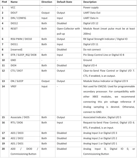
(33) End devices communicate with routers if the destination is not adjacent the end device, the routers determine the route a packet will take to reach its destination. For example if end device A wants to communicate with end device B then any routers between them will be used to as a route for the communication to take place. The number of routers between device A and B are the number of hops. When in operation the XBee modules may use a mesh topology or star topology with the appearance of each node be a single hop away. This means that routing decisions and packet transmission techniques are provided by the XBee module so that all packet transmissions appear as a single hop from peer to peer or peer to coordinator.. 4.3.3 XBee Hardware Specification The XBee module has 20 pins, which are used for powering the module, controlling the module, communicating with the module and input/output from the module. The details of these pins are given in Table 4 and their position on the XBee module given in Figure 5. There are 4 analogue input channels with 10 bit resolution capable of reading from 0 to 1.2 volts. These analogue channels can be configured as digital inputs or outputs, 7 additional digital inputs/outputs can also be configured.. Figure 5 XBee Module pin numbering (top view). pg. 18.
(34) Table 4 XBee Module pin information Pin#. Name. Direction. Default State. Description. 1. VCC. -. -. Power supply. 2. DOUT. Output. Output. UART Data Out. 3. DIN / CONFIG. Input. Input. UART Data In. 4. DIO12. Both. Disabled. Digital I/O 12. 5. RESET. Both. Open-Collector with. Module Reset (reset pulse must be at least. pull-up. 200ns). 6. RSSI PWM / DIO10. Both. Output. RX Signal Strength Indicator / Digital IO. 7. DIO11. Both. Input. Digital I/O 11. 8. [reserved]. -. Disabled. Do not connect. 9. DTR / SLEEP_RQ/ DIO8. Both. Input. Pin Sleep Control Line or Digital IO 8. 10. GND. -. -. Ground. 11. DIO4. Both. Disabled. Digital I/O 4. 12. CTS / DIO7. Both. Output. Clear-to-Send Flow Control or Digital I/O 7. CTS, if enabled, is an output.. 13. ON / SLEEP. Output. Output. Module Status Indicator or Digital I/O 9. 14. VREF. Input. -. Not used for EM250. Used for programmable secondary processor. For compatibility with other. XBEE. modules,. we. recommend. connecting this pin voltage reference if Analog sampling is desired. Otherwise, connect to GND. 15. Associate / DIO5. Both. Output. Associated Indicator, Digital I/O 5. 16. RTS / DIO6. Both. Input. Request-to-Send Flow Control, Digital I/O 6. RTS, if enabled, is an input.. 17. AD3 / DIO3. Both. Disabled. Analog Input 3 or Digital I/O 3. 18. AD2 / DIO2. Both. Disabled. Analog Input 2 or Digital I/O 2. 19. AD1 / DIO1. Both. Disabled. Analog Input 1 or Digital I/O 1. 20. AD0. Both. Disabled. Analog. /. DIO0. /. Commissioning Button. Input. 0,. Digital. IO. 0,. or. Commissioning Button. 4.3.4 IoT adaptation In order to provide internet connectivity to an XBee based WSN an application gateway is required to translate ZigBee to IPv6 as there are no mechanisms for connecting the XBee WSN to the internet without a gateway.. 4.4 6LoWPAN Structure A 6LoWPAN WSN consists of nodes and an edge router (application gateway) which communicate over a medium that uses modulated radio signals. The way in which the nodes communicate with the edge pg. 19.
(35) router and each other is the type of topology. A star topology was implemented for simplicity as there is a high complexity in implementing nodes that can act as routers for the mesh or tree topologies. The nodes require a 6LoWPAN stack, and the edge router requires a 6LoWPAN-IPv6 translation stack.. 4.4.1 6LoWPAN Stack Requirements A 6LoWPAN stack enables application to application communication between an application on a web server and an application on a 6LoWPAN node, as shown in Figure 6. The stack on the edge router must translate between IPv6 format and 6LoWPAN format and the node must decode and encode the 6LoWPAN format to achieve application to application communication. The stacks allow the abstraction of the communication to a simple peer to peer connection between the applications. Similar to ZigBee the 6LoWPAN stack operates above a MAC and PHY layer, defined by the IEEE 802.15.4 standard.. Figure 6 IPv6 and 6LoWPAN stack operation to give Server application to Sensor Application communication. The IEEE 802.15.4 Standard defines radio parameters in the PHY layer, and in the MAC layer network management, and communication techniques are defined. The 6LoWPAN stack requires the functionality provided by the IEEE 802.15.4 MAC layer to operate.. pg. 20.
Figure

![Table 1 Comparison of various wireless sensor network technologies [48]](https://thumb-us.123doks.com/thumbv2/123dok_us/8378566.320075/24.595.73.525.162.459/table-comparison-various-wireless-sensor-network-technologies.webp)

+7


Outline
Code Composer Studio Setup – 6LoWPAN Module
Eclipse Remote Debugging
Visual Studio Setup
OpenVPN Client Configuration
IPv6 UDP Encapsulation
Processing Tunnel Data
Serial Has Data
Microcontroller Radio Interface for 6LoWPAN stack
IoT Server Implementation
Quality of Service parameters for XBee IoT Platform
Related documents
The following inclusion criteria had to be met: (1) ran- domized controlled clinical trial (RCT); (2) population: type 2 diabetes mellitus diagnosed with periodontitis; (3)
Saliva acts by blocking C4 cleavage and deposition of C4b on the classical pathway activation surface and, in the alternative pathway, saliva bind to initial components of the
Impact of high-flow nasal cannula oxygen therapy on intensive care unit patients with acute respiratory failure: a prospective observational study. Sztrymf B, Messika J, Bertrand F,
Prevalence and factors associated with one-year mortality of infectious diseases among elderly emergency department patients in a middle-income country.. Maythita Ittisanyakorn 1,2
Although the information on cold-set gelation is limited as compared to that on heat-induced gelation, the results have showed that cold-set gels are different
The work is not aimed at measuring how effective your local polytechnic is, but rather to see what measures different community groups, including potential students, use when
The nutritive value in vitro organic matter digestibility, neutral detergent fibre and nitrogen content of Aries HD was similar to that of Yatsyn 1 perennial ryegrass, from
2 Equity Market Contagion during the Global Financial Crisis: Evidence from the World’s Eight Largest Economies 10..
