Invited Paper
W-band Gyro-devices Using Helically Corrugated Waveguide and
Cusp Gun: Design, Simulation and Experiment
W. He*, C. R. Donaldson, F. Li, L. Zhang, A. W. Cross, A. D. R. Phelps, K. Ronald, C. W. Robertson, C. G. Whyte, A. R. Young
SUPA, Department of Physics, University of Strathclyde, Glasgow, G4 0NG, Scotland, UK
*Email: [email protected] (Received 18 November 2010)
Abstract: This paper presents the design and simulation of W-band Gyro-devices using helically corrugated waveguides as the beam-wave interaction region and a cusp gun as the electron beam source. The electron beam system and the beam-wave interaction were optimized through numerical simulations by using a particle-in-cell (PIC) code MAGIC to predict (calculate) the output power and frequency bandwidth. The beam cross sectional measurement using a scintillator plate confirmed that an axis encircling electron beam was achieved with the designed beam parameters of current 1.5 A and energy 40 keV. The W-band helically corrugated interaction region for the gyrotron backward wave oscillator (Gyro-BWO) was manufactured with a dispersion from 80
GHz to 110 GHz measured using a vector network analyser which was found to be in good agreement with simulations and theory. The Gyro-BWO achieved frequency-tuneable operation by adjusting the magnetic field in the interaction cavity. A -3 dB bandwidth of ~84-104 GHz and output power ~10 kW were simulated using the electron beam from the cusp gun. The gyrotron travelling wave amplifier (Gyro-TWA) is designed to have a -3 dB frequency bandwidth of 90-100 GHz, output power of 10 kW and saturated amplification gain of 40 dB.
Keywords: Gyro-devices, Gyro-BWO, Gyro-TWA, Helically Corrugated Waveguide, Cusp Gun
1. Introduction
High-power, high-frequency, coherent radiation sources, especially in the range of mm and sub-mm wavelengths, have attracted significant research interest recently due to their desirable applications in many areas such as remote sensing [1], medical imaging [2], plasma heating [3] and spectroscopy [4]. Gyro-devices are promising candidates to fulfill such a demand due to their inherent characteristic fast wave interaction. A helically corrugated waveguide has been demonstrated with a wave dispersion that has a near constant group velocity in the region of small axial wave number [5]. This allows broadband microwave amplification to be achieved in a gyrotron travelling wave amplifier (Gyro-TWA) and wide frequency tuning in a Gyro-BWO as demonstrated by our previous experiments in X-band [6,7,8].
and output power when compared with its counterparts using cylindrical smooth bore waveguides. Previous experiments using such a microwave system at Ka-band achieved an output power of ~1 MW, an efficiency of 10%, a frequency tuning band of 15% using a 20 ns, 300 keV electron beam [11]. Recently a relative frequency-tuning band of 17% at X-band with 16.5% electronic efficiency was achieved [12,13] at the second harmonic of the electron cyclotron mode using a three-fold helically corrugated waveguide and an axis-encircling electron beam.
Variations to increase the bandwidth of gyrotron amplifiers have been investigated [14,15]. For example, a series of gyro-amplifiers have obtained 16% efficiency at a frequency of 5
GHz with a uniform magnetic field, increasing to 26% efficiency with 7% bandwidth using a tapered field [16]. Recently, impressive experimental results on a gyro-TWT were achieved by Chu et al., who studied the amplifier at the fundamental cyclotron harmonic. By stabilizing oscillations with the use of an interaction structure with distributed wall losses, this 35 GHz
Ka-band amplifier produced 93 kW of power at 26.5% efficiency and 70 dB gain with a -3 dB
bandwidth of 8.6% [17]. Gyro-TWA experiments based on a helically corrugated waveguide have been undertaken at Strathclyde University for the last few years. Experiments in X-band achieved 1.1 MW output power with 30% electronic efficiency, 21% relative -3 dB bandwidth [18 ,19].
Research projects investigating Gyro-BWOs and Gyro-TWAs in the W-band using helically corrugated waveguides started at Strathclyde University in 2010. Presented in this paper is the design, simulation of the gyro-devices and initial experimental results of the W-band Gyro-BWO.
2. Cusp electron gun
A novel cusp electron beam source is used to drive the beam wave interaction in the W-band Gyro-BWO and Gyro-TWA. This electron gun is required to produce an axis-encircling, annular shaped electron beam of current 1.5 A, energy 40 keV and a pitch alpha (= the ratio between the transverse momentum and the axial momentum of the electron beam) of up to 2 with the beam optimized for interaction with an operating eigenwave in the cavity. For the gyro-BWO interaction a pitch alpha of 1.5-2 could be used to drive the high efficiency beam-wave interaction. However for the Gyro-TWA a slightly lower pitch alpha in the range of 1.0-1.2 is preferred to maintain zero-drive stability of the amplifier.
The cusp electron gun is a novel way of creating an axis-encircling annular electron beam ideal for use in gyrotron devices. Conventional electron guns mainly used in gyrotron devices are the Magnetron Injection Gun (MIG) and Pierce gun. Mode selectivity is poor in the MIG as the coupling for such a beam is strongest to the fundamental mode. In the Pierce gun case, a straight linear electron beam is kicked into an axis-encircling path. However, for this CW source the Pierce gun would not be a suitable source as the kicker magnet is feasible primarily in pulsed mode. Due to the high power of the spent electron beam, an annular shaped electron beam is desirable for beam energy recovery using a depressed collector method. Therefore, the cusp gun is the best choice of electron gun for this Gyro-BWO and Gyro-TWA.
Schmidt described a threshold for magnetic mirroring and the effects on the electrons after they have passed through the cusp region, namely, azimuthal rotation around the central axis of symmetry due to conservation of the electron canonical momentum given in equation (1) which is satisfied by an off-axis beam, where vθ is zero.
θ θ
P -qrA =mv rθ (1)
When the magnetic field changes sign the vector potential also changes sign therefore cannot be zero to still satisfy this equation.
θ
A v θ
Following Schmidt et al. [20] continuous efforts and progress have been made through both theoretical analysis and experimental study in the generation of cusp-based electron-beam sources [22,23]. Special concentration was paid on the methods to produce an ideal sharp cusp shape by using complex arrays of magnetic coils, magnetic poles, and, possibly, magnetic material inside the cathode [ 24 , 25 , 26 ]. These studies have been based on the configuration where a magnetic cusp was located at or after the anode where large cusp amplitude was required due to a fully accelerated electron momentum. However the electron gun designed for W-band gyro-devices was based on a “smooth” cusp [27], formed by two simple coils without any magnetic shaping poles, located immediately after the cathode.
3. Numerical simulation of the cusp gun
The 3D PIC (Particle in Cell) code MAGIC was used to simulate the cusp gun. A slice through the geometry, in polar coordinates, can be seen in Fig. 1. Two solenoids are used, one with a negative polarity. The negative coil is positioned immediately behind the cathode and the cavity coil midway along the waveguide. An accelerating voltage of 40 kV is applied to the diode which results in an emitted current density of 9.6 A/cm2 from the cathode. The shape of the cathode and the electron emitting surface, the positions and dimensions of the solenoids have been optimized to ensure the best electron beam qualities when it gets compressed, passes through the magnetic cusp and enters the higher magnetic field region. Desirable electron beam properties include a uniform beam density, less off-centering coupling with a low velocity spread. At the end of the electron beam drift region a cylindrical step down reflector of radius 0.837 mm is used to stop microwaves returning to the diode. The input waveguide to the helical structure has a radius of 1.3 mm suitable for use at W-Band frequencies.
The simulated electron-beam trajectory from the cusp gun with its magnetic-field profile (B0 = 1.82 T) is shown in Fig. 1. The cross-sectional shape of the beam at the downstream
region is also shown in Fig. 1, and it clearly shows an annular-shaped axis-encircling beam. The magnetic field profile is a smooth transition from the cathode to the downstream uniform magnetic-field region, with the cusp being located at ~4.6 mm in front of the emission surface.
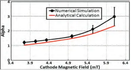
From simulation, to obtain an alpha value of one to three, the required magnetic field at the cathode was ~3.0–6.7 mT. At a constant value of B0, a larger α value could be achieved by
increasing the magnetic-field amplitude at the cathode (Bc). The simulated average alpha of
average values. The alpha values calculated from the previous equation are also shown in Fig. 2 for comparison. Minimum axial velocity spreads of ~8% and relative alpha spreads of ~10% were achieved at an alpha value of 1.65 at this constant magnetic field. At B0 values of 2.1
and 1.7 T, the optimum alpha spreads were ~23% and ~15% for alpha values of 3 and 1.2, respectively, and the corresponding axial velocity spreads for these cases were ~20% and ~10%. At the central magnetic field B0 of 1.82 T, the beam had an inner and an outer radius of
[image:4.595.165.430.194.316.2]0.23 mm and 0.42 mm, respectively, with an envelope ripple ~13%. Beam transport through the tube was measured to be 100% after the initial low potential electrons were reflected.
Fig. 1 Cross-section of cusp geometry with simulated electron beam trajectories.
Fig. 2 Numerically simulated and analytically calculated alpha values for different values of cathode magnetic field at B0 = 1.82 T.
4. Cusp gun experiment
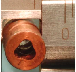
Based on the simulation results for one particular set of parameters which yields an optimized beam for an alpha range of 1–2, the cusp electron gun of Fig. 3 was manufactured. The cathode assembly and the anode were arranged in a coaxial configuration Fig. 3. The cathode head included three following interchangeable parts: outer, inner focusing electrodes, and the thermionic cathode emitter which was located between the electrodes and constructed from porous tungsten impregnated with barium oxide. Facing the cathode head was an interchangeable anode tip.
[image:4.595.188.409.352.473.2]Fig. 3 Schematic diagram of the cusp electron gun with simulated and measured magnetic field profiles overlaid.
Fig. 4 Scintillator recorded beam cross-sectional shape at the downstream region.
5. Interaction cavity of Gyro-BWO
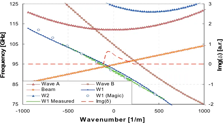
Fig. 5 shows the photo of the helically corrugated interaction region. The 3-fold helically corrugated waveguide resonantly couples two partial waves, one the A wave (Fig. 6), is the near cutoff TE21 mode, the other, the B wave, is a traveling TE11 mode. When Bragg resonant
conditions are met, the coupling results in two eigenwaves W1 and W2 as shown in Fig. 6.
One of the eigenwaves (W1) has a near constant group velocity at small wavenumber over a
[image:5.595.232.364.524.649.2]wide frequency range. This ideal dispersion property allows wide frequency bandwidth to be achieved for a gyrotron travelling wave amplifier as well as for gyro-BWOs.
Fig. 5 A photo of the helically corrugated waveguide for the W-band Gyro-BWO.
line and the growth rate at an interaction frequency of ~94 GHz as it interacts with the operating eigenwave at a magnetic field of ~1.83 T are shown in Fig. 6.
The measured operating eigenwave was found to be in very good agreement when compared with the results simulated from MAGIC and calculations based on perturbation theory. In the simulation using the MAGIC code, a left-polarized circular wave of one frequency was injected into the right-hand helical waveguide, and a component of the electric field inside the waveguide was measured along the axial direction. The measured field was then numerically analyzed and the axial wavenumber of the eigenwave was therefore obtained for that frequency.
75 85 95 105 115 125
-1000 -500 0 500 1000
W av enum ber [1/m ]
F
re
q
ue
nc
y
[
G
H
z
]
-2 -1 0 1 2 3
Im
g
(δ
) [a
.r
.]
Wave A Wave B
Beam W1
W2 W1 (Magic)
[image:6.595.115.478.229.431.2]W1 Measured Img(δ)
Fig. 6 Dispersion diagram of the operating eigenwave, the second harmonic electron cyclotron mode, an interaction at ~94 GHz and corresponding growth rate of the W-band Gyro-BWO.
6. Simulation of Beam-wave interaction in a Gyro-BWO
The beam-wave interaction of the Gyro-BWO was simulated using Magic when driven by a large-orbit annular shaped electron beam of voltage 40 kV, current 1.5 A and a pitch alpha of 1.6, and the simulated output power and frequency are shown in Fig. 7.
Predicted ourput frequency and power
70 80 90 100 110
1.4 1.6 1.8 2 2.2
B field (T)
Fr
eq (
G
Hz)
4 6 8 10 12
Power (kW)
Freq. (Magic) Freq. (Linear theory) Power (Magic)
[image:6.595.172.421.583.740.2]7. Gyro-BWO Experiment
[image:7.595.171.425.155.340.2]The setup of the experiment is shown in Fig. 8 with the cusp gun shown in the left, helical interaction region in the middle and output window at the right. Two coils, which form a magnetic cusp at the front of the cathode surface, are also shown in Fig. 8.
Fig. 8 The setup of the W-band Gyro-BWO experiment.
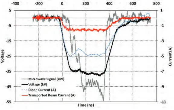
The cusp gun was firstly tested under a pulsed operation mode using a double Blumlein pulsed power system made from a cable. The thermionic cathode is designed to operate in a temperature-limited regime. Microwave radiation has been observed in the Gyro-BWO operation. Typical measured beam voltage, emitting current from cathode, transported current at the downstream side of the cavity and detected microwave traces were recorded and are shown in Fig. 9.
Fig. 9 Recorded traces of beam voltage, emitting current, beam current and microwave radiation.
8. Design of Gyro-TWA
[image:7.595.155.443.476.658.2]}
{
1 2 [ ( ) ]) ( ] ) ( ][ 2 ) )( 2 [( 0 0 2 0 0 3 2 0 0 2 0 2 z H z g z H g h s h h C h h h h h β δ β α δ β δ σ δ δ Δ − − + − Δ + = Δ − − + − Δ + − (2)
The resultant dispersions of the eigenwave and beam cyclotron mode as well as the small signal growth rate are shown in Fig. 10.
g 0 0.25 0.5 0.75 1
80 85 90 95 100 105 110
Frequency (GHz) L in e a r g a in ( a .r .)
(a) (b)
Fig. 10 (a) The dispersion of the eigenwave and electron beam and (b) the small signal growth rate.
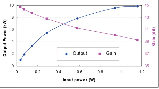
The beam-wave interaction inside the helically corrugated waveguide was simulated by using the 3D PIC code MAGIC. The simulated output power as a function of input power at 96 GHz is shown in Fig. 11.
0 2 4 6 8 10
0 0.2 0.4 0.6 0.8 1 1.2
Input pow e r (W)
[image:8.595.112.487.187.379.2]Ou tp u t P o we r ( k W ) 35 37 39 41 43 45 G a in ( d B ) Output Gain
Fig. 11 Simulated output power as a function of input power.
[image:8.595.135.461.477.660.2]0 2 4 6 8 10
90 92 94 96 98 100
Freq (GHz) Po w e r ( k W ) 25 28 31 34 37 40 G a in ( d B )
[image:9.595.146.454.73.264.2]Power (kW) Gain (dB)
Fig. 12 Simulated performance of the W-band Gyro-TWA.
A side-wall rectangular-to-circular coupler was used to seed the input signal for the Gyro-TWA. A ceramic window constructed in a pillbox cavity was used to serve as a vacuum boundary. This same input coupler of the Gyro-TWA can be used as an output coupler for Gyro-BWO operation. Therefore the coupler was aimed to achieve a high transmission coefficient for a W-band Gyro-BWO working in the frequency range of 84 GHz - 104 GHz as well as a W-band Gyro-TWA working in the frequency range of 90 GHz - 100 GHz. In the design, a Bragg reflector was employed to prevent the microwave radiation from travelling into the cusp gun region. Usage of a Bragg reflector instead of the cut-off waveguide resulted in an increase of the size of the beam tunnel and made it easier for the beam to pass into the interaction region. The optimized coupler achieved a transmission coefficient of better than -1
dB over the whole operating frequency range.
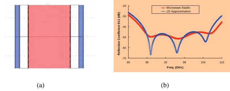
The output window, positioned at the output end of the interaction region, consisted of 3 pieces of dielectric disks, with the middle sapphire disk serving as the vacuum boundary and two quartz disks at the both sides to increase the operating bandwidth. The thickness of the disks and the separation distances of the disks were optimized by analytical calculation and finally simulated by CST Microwave Studio. The configuration of the output window and optimized S11 parameter are shown in Fig. 13.
-70 -60 -50 -40 -30 -20
80 86 92 98 104 110
Freq. (GHz )
R e fl e c ti o n C o e ffi c ie n t S 1 1 (d B ) Microwave Studio 1D Approximation
(a) (b)
[image:9.595.100.500.574.733.2]
9. Conclusion
A Gyro-BWO with a -3 dB frequency tuning range of 84-104 GHz and a Gyro-TWA with an instantaneous amplification bandwidth of 90 – 100 GHz were designed and manufactured for high power CW output of up to 10 kW. The thermionic cusp gun based electron beam to drive the beam-wave interactions of the gyro-devices was successfully operated and the measured beam energy, current and pitch alpha were in excellent agreement with the simulated results from the PIC code MAGIC. Microwave radiation from the Gyro-BWO was observed and continuous tuning of the output frequency from 92-102 GHz achieved in the initial experiment by changing the cavity magnetic field. Furthermore, the W-band Gyro-TWA was predicted to have a saturated gain of ~40 dB and interaction efficiency of 17%. The interaction cavity, input coupler and output window were designed and optimized.
References
[1] W. M. Manheimer, G. Mesyats, and M. I. Petelin, in Applications of High-Power Microwaves, edited by A.V.Gaponov-Grekhov and V.L. Granatstein, Artech House, Boston, pp. 169-207, (1994).
[2] D. D. Amone, C. M. Cielsla, A. Corchia, S. Egusa, et al, Proc. SPIE Terahertz Spectrosopy Applicat. II., pp. 3823, Munich, Germany, (1999).
[3] T. Imani, N. Kobayashi, R. Temkin, M. Thumm, M.Q. Tran and V. Alikaev, “Electron Cyclotron Heating and Current Drive System”, Fusion Eng. Design, 55, no. 2-3, pp. 281, (2001).
[4] T. I. Smirnova, A. I. Smirnov and R. B. Clarkson, "W-band(95GHz)EPR Spectroscopy of Nitroxide Radicals With Complex Proton Hyperfine Structures: Fast Motion", J. Phys, Chem., 99, No. 22, pp. 9008, (1995). [5] G. Burt, S. V. Samsonov, K. Ronald, G. G. Denisov, et al., ‘Dispersion of helically corrugated waveguides:
Analytical, numerical, and experimental study’, Phys. Rev. E, 70, (4), 046402, (2004).
[6] A. W. Cross, W. He, A. D. R. Phelps, K. Ronald, et al., ‘Helically corrugated waveguide gyrotron traveling wave amplifier using a thermionic cathode electron gun’, Appl. Phys. Lett., 90, (25), 253501, (2007). [7] W. He, K. Ronald, A. R. Young, A. W. Cross, et al., ‘Gyro-BWO experiments using a helical interaction
waveguide’, IEEE Trans. Electron Devices, 52, (5), pp. 839, (2005).
[8] W. He, A. W. Cross, A. D. R. Phelps, K. Ronald, et al., ‘Theory and simulations of a gyrotron backward wave oscillator using a helical interaction waveguide’, Appl. Phys. Lett., 89, (9), 091504, (2006).
[9] S. Y. Park, R. H. Kyser, C. M. Armstrong, R. K. Parker and V. L. Granatstein, “Experimental study of a Ka- band gyrotron backward-wave oscillator”, IEEE Trans. Plasma Sci., vol.18, pp321-325, June, (1990).
[10] C. S. Kou, S. G. Chen, L. R. Barnett, H. Y. Chen and K. R. Chu, “Experimental study of an injection-locked gyrotron backward-wave oscillator”, Phys. Rev. Lett., vol. 70, no. 7, pp924-927, (1993).
[11] V. L. Bratman, G. G. Denisov, V. N. Manuilov, S. V. Samsonov and A. B Volkov, Digest of Int. Conf. Infrared and Millimeter Waves, Toulouse, France, O. Portugall and J. Leotins Eds. (ISBN 2-87649-035-8), (2001).
[13] W. He, A. W. Cross, A. D. R. Phelps, K. Ronald, C. G. Whyte, S. V. Samsonov, V. L. Bratman, and G. G. Denisov, Appl. Phys. Lett. 89, 091504, (2006).
[14] K. R. Chu, A. T. Drobot, V. L. Granatstein, and J. L. Seftor, IEEE Trans. Electron Devices MTT-27, 178– 187, (1979).
[15] M. Blank, in Generation and Application of High Power Microwaves, edited by R. A. Cairns and A. D. R. Phelps,Proceedings of the 48th Scottish Universities SummerSchool in Physics, IOP, Bristol, (1996). [16] P. E. Ferguson, G. Valier, and R. S. Symons, IEEE Trans. Microwave Theory Tech. 29, 794–799, (1981). [17] K. R. Chu, H.Y. Chen, C. L. Hung, T. H. Chang, L. R. Barnett, S. H. Chen, and T. T. Yang, Phys. Rev. Lett.
81, 4760–4763 (1998).
[18] G. G. Denisov, V. L. Bratman, A. W. Cross, W. He, A. D. R. Phelps, K. Ronald, S. V. Samsonov and C. G. whyte, “ Gyrotron travelling wave amplifier with a helical interaction region”, Phys. Rev. Lett., 81, pp5680- 5683, (1998).
[19] V. L. Bratman, A. W. Cross, G. G. Denisov, W. He, A.D.R. Phelps, K. Ronald, S.V. Samsonov, C. G. Whyte and A. R. Young, ‘High Gain Wide-Band Gyro-Travelling Wave Amplifier With A Helically Corrugated Waveguide’, Phys. Rev. Lett., 84, Pp2746-2749, (2000).
[20] Schmidt G., Nonadiabatic Particle Motion in Axialsymmetric Fields, The Physics of Fluids, 5, 994-1002, (1962).
[21] J. Sinnis and G. Schmidt, “Experimental trajectory analysis of charged particles in a cusped geometry,”
Phys. Fluids, vol. 6, no. 6, pp. 841–845, Jun. (1963).
[22] M. J. Rhee and W. W. Destler, “Relativistic electron dynamics in a cusped magnetic field,” Phys. Fluids,
vol. 17, no. 8, pp. 1574–1581, Aug. 1974.
[23] W.W.Destler and M.J. Rhee, “Radial and axial compression of a hollow electron beam using an asymmetric magnetic cusp,” Phys. Fluids, vol. 20, no. 9, pp. 1582–1584, Sep. (1977).
[24] G. P. Scheitrum, R. S. Symons, and R. B. True, “Low velocity spread axis encircling electron beam forming system,” in IEDM Tech. Dig., pp. 743–746, (1989).
[25] K. T. Nguyen, D. N. Smithe, and L. D. Ludeking, “The double-cusp gyrogun,” in IEDM Tech. Dig., pp. 219–222, (1992).
[26] D.A.Gallagher, M. Barsanti, F. Scafuri, and C. Armstrong, “High-power cusp gun for harmonic gyro-device applications,” IEEE Trans. Plasma Sci., vol. 28, no. 3, pp. 695–699, Jun. (2000).
[27] W. He, C. G. Whyte, E. G. Rafferty, A. W. Cross, A. D. R. Phelps, K. Ronald, A. R. Young, C. W. Robertson, D. C. Speirs, and D. H. Rowlands, “Axis-encircling electron beam generation using a smooth magnetic cusp for gyrodevices,” Appl. Phys. Lett., vol. 93, no. 12, 121501, Sep. (2008).