Scalable Real-Time Controller Hardware-
In-the-Loop Testing for Multiple Interconnected
Converters
Andreas Avras
Electronic & Electrical Engineering University of Strathclyde Glasgow, United Kingdom [email protected]
Andrew J. Roscoe
Electronic & Electrical Engineering University of Strathclyde Glasgow, United Kingdom [email protected]
Graeme M. Burt
Electronic & Electrical Engineering University of Strathclyde Glasgow, United Kingdom
Abstract -This project is aiming to make the first steps in
in-vestigating and pushing the boundaries of real-time simulation. To that end it will focus on real-time representation of converter devices on different platforms, enabling the future coupling of prototyping controllers to power system simulation tools. The small time-step, high fidelity representation of the converter devices and the large time-step model of the grid will be carried out on RTDS Technologies, RTDS and perhaps expanding the attempt, on OPAL-RT Technologies, OPAL-RT Simulator in the future. The controller prototyping, including the converter switching strategy will be implemented on ADI’s rtX and the use of other rapid controller prototyping systems will also be evalu-ated. This will effectively allow the exploration of the scalability and limits of such schemes. Namely, how many converters can be simulated on real-time simulation devices? How many con-trollers can be implemented on a prototyping platform using modern microprocessors?
Index Terms–Hardware-In-the-Loop, prototype controllers,
power electronic converters, real-time simulation.
I. INTRODUCTION
The increased complexity of power networks and the large scale integration of intermittent energy sources, paired with the proliferation of power electronics, present many challeng-es in terms of quality and security of supply.
The aforementioned recent and on-going rapid growth of the wind and renewable industry means that more and more converter-connected devices are present within the national electricity grid. The behavior of these converters is highly dependent on the mix of other devices connected to the net-work along with the topology and the resulting system dy-namics at the minute, second, millisecond, and even micro-second timescales. Traditional simulations of overall system behavior, utilized steady-state or “pseudo steady state” tech-niques and this was adequate for power networks dominated by generation connected via rotating plant. For emerging power networks, this is no longer true. Converters have com-plex response at timescales right down to the switching fre-quency of the power electronics. The way that converter-connected devices, including High Voltage DC (HVDC) links, provide inertial response is entirely dependent on their high-bandwidth control software and power electronic filter responses.
These facts make the accurate design, analysis and simula-tion of modern power networks an extremely difficult and complex procedure in terms of computational time and re-sources. To that end this project will investigate the real-time capabilities of prototyping controllers and power system sim-ulation tools. This will enable further exploration of the scalability and limits of such schemes by identifying the most crucial elements of this type of network analysis and repre-sentation.
First, a brief overview of the different simulation tech-niques used today along with comments on their respective shortcomings and benefits is given. Next the proposed simu-lation configuration is presented, followed by the theoretical description of the STATCOM model. Last is the showcase of the practical implementation of the model along with prelimi-nary results and conclusions.
II. OVERVIEW OF SIMULATION TECHNIQUES
Simulation is a crucial element in the design and develop-ment of power generation and transmission systems. Simula-tion analysis is conducted to verify the system’s stability and response over time under different scenarios.
The most commonly applied simulation technique is the discrete-time, software simulation. It makes use of scaled-down models of real power system components, based on fundamental frequency responses and mathematical represen-tations of system dynamics. In these steady-state simulations, time moves in fixed steps. At the end of each step the varia-bles and states of the system are computed. The time it takes for these functions and equations to be resolved can be shorter or longer than the actual time-step of the simulation [1], a fact that does not interfere with the accuracy of the results. This technique is useful during the early stages of design in order to analyse distinct components rather than a complex system in its entirety. The models are usually implemented on high end, in terms of computational power, PCs [2].
micro-turbines present the challenge of more sensitive indus-trial loads in terms of power quality [4]. The widespread use of the microprocessor-based controls of fast-acting power electronic devices along with the benefits of faster reaction times of the power networks, is introducing an extended spec-trum of harmonics to the system.
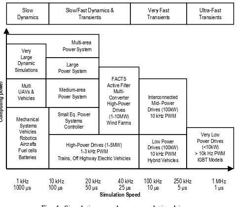
[image:2.595.53.292.161.371.2]To get in context with the time-step and computing re-quirements of present day applications a comprehensive graph is provided below in fig. 1 reproduced from [1].
Fig. 1: Simulation speed - power relationship
Moving from left to right are applications that require in-creasingly smaller time-step and from bottom to top are the applications with increasing demand in computational power.
A way to accurately predict and plan ahead for the mitiga-tion of disturbance and instability factors is real-time simula-tion. In this case though, the accuracy of the results is relevant to the time demanded to produce them [1] i.e. the simulator must be faster than the clock duration of the time-step. There are different approaches to realising a real-time simulation environment.
The software-based real-time approach, involves the simu-lation of the whole system on a real time digital simulator. Depending on the architecture, the simulator might have a single or many parallel digital processors. This allows the option of either using a single processor to carry out all the calculations or of dividing the system under test into zones and allocating each zone to a dedicated processor [5]. Another variation is the utilisation of more than one real-time simula-tors carrying out the necessary computations. The latter con-cept, because of the intercommunication through physical inputs and outputs, introduces the burden of ensuring and preserving the integrity of the signals [1]. The frequency bandwidth of the results is up to 10 kHz which might not be accurate enough for the switching operation of the power converters.
The hardware-based real-time approach or Hardware-In the-Loop (HIL) simulation, involves the modelling represen-tation of only a part of the system while the rest is actual hardware. There are two distinct cases of this concept. Power-Hardware-In-the-Loop (PHIL) refers to the implementation of
a controller on a real time simulator or a Rapid Control Proto-typing (RPC) unit, connected to a physical power network. This method offers easier debugging and implementation of controllers. Controller-Hardware-In-the-Loop (CHIL) refers to the connection of an actual controller to a simulated net-work [1]. CHIL is used for controller testing at the early stag-es of dstag-esign offering high experimental repeatability of events. Real-time simulation also has its limitations as the highly accurate simulation of the switching events of the con-verters, requires high frequency bandwidth. Increasing the frequency bandwidth leads to the implementation of smaller time-steps and more accurate models. Finally increasing the representation accuracy corresponds to an increase in compu-tational time [5].
III. PROPOSED SIMULATION APPROACH
[image:2.595.306.554.332.415.2]The importance of numerically accurate solutions is made apparent by taking into account the various shortcomings discussed in II and considering them in context with the very high precision demands of the power electronic converter simulations. To that end the parallel implementation approach of a real-time digital simulator in conjunction with a high performance, rapid prototyping controller unit is proposed. The hardware configuration is illustrated in fig. 2 below.
Fig. 2: Simulation configuration
The real-time digital simulator, RTDS (RTDS™) combines real-time operation and accurate digital simulation. The mod-els can be built in two resolution environments of 50 µs and 2 µs accuracy on a host PC and then downloaded to the simula-tor to be executed on one or more parallel digital signal pro-cessors. The monitor and control of the models is achieved through a dedicated software suite, RSCAD.
The rapid control prototyping unit is selected to be the rtX real-time simulator (ADI™) due to the familiarity with MATLAB/Simulink and the relative ease of controller inser-tion. A controller realized on rtX is flexible, faster in its im-plementation and easier to debug [4]. The rtX uses standard personal computer (PC) technology with a 6core Intel Xeon processor for fast, highly accurate, assessing of control strate-gies and real-time simulation. Mathematical models of the controller under test are imported to the dedicated software suite of the host PC called ADvantage Framework, in the na-tive C programming language. After their upload on the rtX, the user has the choice of using the available ADC and DAC cards or even the Dynamically Programmable Gate Array (DPGA) card to interface with the other parts of the distribut-ed simulation.
For this first interconnected modeling attempt the model of a Static Synchronous Compensator (STATCOM) will be used. Its simplified circuit is illustrated in fig. 3.
Multi-area Power System
Slow
Dynamics Slow/Fast Dynamics & Transients Transients Very Fast TransientsUltra-Fast
Mechanical Systems Vehicles Robotics Aircrafts Fuel cells Batteries Multi UAVs & Vehicles Very Large Dynamic Simulations Very Low Power Drives (<10kW) > 10k Hz PWM
IGBT Models High-Power Drives (1-5MW)
1-3 kHz PWM Trains, Off Highway Electric Vehicles
Low Power Drives (100kW)
10 kHz PWM Hybrid Vehicles Small Eq. Power
Systems Controller Testing Medium-area Power System Large Power System FACTS Active Filter Multi-Converter High-Power Drives (1-10MW) Wind Farms Interconnected Mid- Power Drives (100kW)
10 kHz PWM
1 kHz 10 kHz 20 kHz 40 kHz 100 kHz 250 kHz 1 MHz 1000 μs 100 μs 50 μs 25 μs 10 μs 5 μs 1 μs
Fig. 3: Simplified STATCOM diagram
The electrical part will be implemented on RTDS. The grid side of the network will be represented in the large time-step and the STATCOM on the small time-step. The dq control and PWM switching calculation will be stripped from RSCAD and modelled on the rtX
Measurements of voltages and currents required will be gathered in real-time and transmitted to the rtX. The interface can be realised by the Digital to Analogue Converter (DAC) GTAO I/O channel. The signals are carried by an optically shielded cable and received by the Analogue to Digital Con-verter (ADC) I/O card of the rtX. There the dq and PWM algorithms will make the appropriate decisions based on the
transformed id, iq and udc loops [6]. The gate drive pulses will
be transmitted from the DPGA I/O card of the rtX. It will be useful at this point to consider that the PWM signal is not constant. Its main parameter is the duty cycle, D which de-scribes the proportion of "on" time of the pulses for a speci-fied interval [7]. Equation (1) describes D.
(1)
Where τon is the time of the on signal, T is the period and
0≤D≤1. This parameter along with the switching frequency is the signal that will be sent through the rtX’ s DPGA card and received by the Analogue to Digital Converter (ADC) GTAI I/O channel of the RTDS, effectively closing the loop of the simulation.
IV. MODEL THEORITICAL DESCRIPTION
STATCOMs provide support to electricity networks for a variety of power system stability conditions such as voltage regulation and power factor correction. The device is com-prised of a Voltage Source Converter (VSC) with a DC-link capacitor, a coupling reactor, and a harmonic filter. The con-nection to the rest of the network is achieved by a step-down transformer. Its operating principle is based on the controlla-ble voltage of the VSC and the voltage drop at the reactor that dictates the reactive power absorption from or injection to the system as shown by (2).
(2)
Where VS is the voltage at the grid side of the coupling
trans-former and Vc is the voltage at the VSC side of the
transform-er. δ is the angle between the grid and VSC bus and X is the leakage reactance of the transformer. When the current at the AC side of the STATCOM is leading the voltage by 90°, then reactive power is absorbed while when the current is lagging
the voltage by 90°, reactive power is injected to the power system in the form of reactive current [8] as seen in (3).
(3)
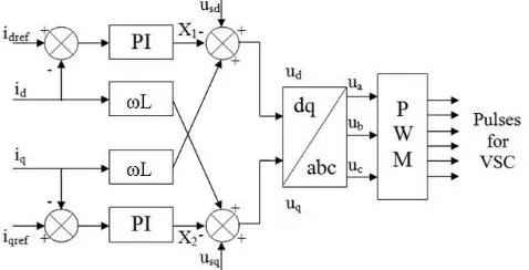
[image:3.595.308.547.160.312.2]To ensure this kind of operation d-q vector control is em-ployed. This control strategy involves the transformation of three phase voltages and currents into the dq reference frame and is illustrated in fig. 4 below.
Fig. 4: dq STATCOM control.
The angle of the transformation is obtained from the three phase voltages of the grid side with a Phase Locked Loop (PLL). The values that are being transformed are:
The voltage of the grid (uSabc) is converted to usd, usq.
The current through the load (iLabc) is converted to the
reactive current component, iqref.
The compensation current of the converter (ic) is
trans-formed to the active component id and reactive
com-ponent iq.
Additionally the voltage of the dc-link capacitor udc is
monitored and kept stable by a PI controller and an
ex-ternal reference udcref, in order to extract the active
cur-rent reference, idref.
These signals are then fed to the current decouple
control-ler seen in fig. 5, to generate the output voltage vectors ud and
uq. One last inverse Park's transformation from dq to abc and
the reference voltages, ua, ub, uc are obtained. By adjusting the
magnitude and the phase of the VSC voltage, the three phase reference signals are fed to the PWM scheme to generate the switching pattern for the VSC. From there, the six pulse sig-nals are extracted for driving the power electronic switches of the VSC and in turn generate the desired reactive power.
[image:3.595.308.547.581.703.2]V. PRACTICAL IMPLEMENTATION OF THE MODEL
Fig. 6: MATLAB/Simulink STATCOM model The STATCOM is first modeled in MATLAB/Simulink
environment to verify it’s electrical and control behavior. The model is depicted in Fig. 6 above.
The time-step of the simulation was set to 2 μs. The load is connected at 0.6 s. The orderly operation of the model can be deducted from fig. 7 that shows the active and reactive cur-rent components, fig. 8 shows the DC-link voltage and fig. 9 shows the peak, line to line, rms voltage of the network and the current of the load.
[image:4.595.61.274.438.706.2]When the load connects, it draws active and reactive pow-er. This causes a disturbance at the DC - link voltage that is compensated within 0.1 s thus regulating the active power. Reactive current is being injected from the STATCOM to regulate the reactive power. The model’s behavior appears to be representative of the operation of the real equipment.
Fig. 7: Active and reactive current component
Fig. 8: DC-link voltage
Fig. 9: System voltage and load current
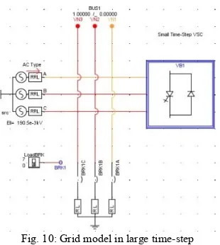
[image:4.595.352.507.502.675.2]The next step is the implementation and real-time simula-tion on the RTDS through a host PC equipped with the RSCAD. The grid side of the network was developed in the large time-step environment (50μs) illustrated in fig. 10. The STATCOM device and the control are carried out at the small time-step domain (2μs), fig. 11, since the converter and its switching scheme require a high fidelity simulation environ-ment [9]. The switching frequency is 3 kHz.
Fig. 10: Grid model in large time-step
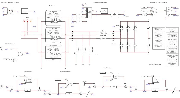
Fig. 11: STATCOM and control model in small time-step
(4)
Where Vs is the voltage of the grid, Vc is the voltage of the
converter, δ is the angle between Vs and Vc. So the amount of
injected reactive power is controlled by Vs.
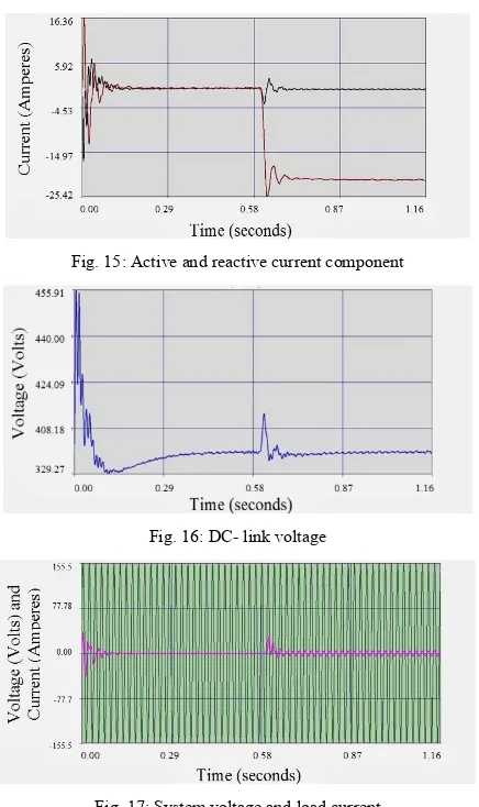
The way the various system values are represented in the RSCAD is different from the MATLAB/Simulink model. Bearing in mind that in this case the load is manually switched on and the VSC valves are manually de-blocked, explains the difference in the time scale of the figures and is the reason of the depiction of different measurements. The calculations for system voltage and reactive power are carried out in the per unit system. The carried out simulation demon-strates that the design behaves accurately and as desired. A further addition to the model is the harmonic filter tuned to compensate the harmonics at the switching frequency of 3 kHz that is inserted between the coupling transformer and the
VSC reactor. The load draws QL=5000Var close to 8.3pu in
[image:5.595.309.538.299.592.2]the 600 kVA system base. When the load is connected through the three phase breaker there is a voltage dip on the grid side of the network that corresponds to 0.021pu, but is quickly dealt with by reactive power injection while the dc side voltage is maintained at a preset value of 400 V. These are illustrated at figs. 12 - 14.
Fig. 12: DC - link voltage
It is worth noticing that there are a lot more spikes in the DC - link voltage compared to the previous simulations. One
possible explanation could be the time delay in the interface of the two different time-step environments.
Fig. 13: Injected reactive power
Fig. 14: System voltage
[image:5.595.52.278.557.698.2]Fig. 15: Active and reactive current component
Fig. 16: DC- link voltage
Fig. 17: System voltage and load current
VI. CONCLUSIONS AND FUTURE WORK
This paper explored the procedure of implementing a mod-el for real-time simulation and transient analysis. The STAT-COM was selected as the modelling case due to the high computational accuracy, necessary for the calculation of the control of its converters' switching scheme. It was demon-strated that both the RTDS and the rtX are capable of individ-ually fulfilling their real-time tasks.
Since their respective efficiency has been verified the mod-els will be more accurately represented and this ongoing pro-ject will focus on the actual coupling architecture of the RTDS and rtX. The intention is to design and configure an optimal testing environment for networks with high penetra-tion on converter controlled and connected devices.
The simulation process will be extended by simulating an increasing number of converters and control schemes on the RTDS and rtX effectively taking the simulation to the next level by exploring the limits and scalability of such a scheme. At this stage the optimization of loop and input/output delays will be of great importance and new techniques will have to be developed for their compensation. The selection of the sampling frequency is equally important as it can lead to un-stable performance of the system. It should be selected at least two orders of magnitude larger than the maximum switching frequency of the converters [10].
Capitalizing on the knowledge and data collected from the creation, evaluation and improvement of this simulation ap-proach, real-time Controller and Power hardware-in-the-loop testing boundaries can be pushed further and novel concepts safely and explored. The industrial sectors where the pro-posed simulation environment can be utilized for testing are:
1. Power networks, incorporating power quality
im-provement and protection devices that are converter-connected and software controlled, having complex high bandwidth responses.
2. More-Electric ships and Aircrafts, where power
sources and propulsion loads are transitioning from ro-tary and constant impedance devices to complex con-verter-connected devices, allowing variable-frequency, variable-voltage and bidirectional flow operation.
3. HVDC multiple interconnected converters and
multi-level converter applications, modeled at switching-level fidelity.
4. Novel concepts of future power grids, utilizing
distrib-uted generation power sources and synthetic inertial responses.
5. Hybrid electric vehicles with hydrogen based power
sources that comprise of batteries, DC/DC converters, fuel-cells and permanent magnet motor drives [1]. With real-time simulation, the interactions of the men-tioned power systems with other control and protection schemes can be tested and evaluated before commissioning. This will provide useful and in depth data for the limits, op-timization and further improvement without the constraints that computational time and power as well as mathematical model complexity, puts on traditional steady-state simula-tions.
VII. REFERENCES
[1] J Belanger et al, "The What, Where and Why of Real-Time Simulation" Opal-RT Publications, PES-GM Tutorial 04, Oct. 2010 pp. 37-49
[2] M. Kezunovic et al, "Transients Computation for Relay Testing in Real- time", IEEE Transaction on Power Delivery, Jul. 1994, vol.9, no.3 pp. 1298-1307
[3] R. Kuffel et al, "RTDS - A Fully Digital Power System Simulator Operat-ing in Real Time", IEEE WESCANEX PROCEEDINGS
[4] O. Nayak, S. Santoso, P. Buchanan, "Power Electronics Spark New Simu-lation Challenges", IEEE Computer Applications in Power, Oct. 2002, pp. 37-44
[5] M. Matar et al, "A High Performance Real-Time Simulator for Control-lers Hardware-in-the-Loop Testing" Energies Journal Article, vol.5, 2012 pp. 1713-1733
[6] C.S Edrington et al, "Rapid Prototyping CHIL Methodology for Ad-vanced Converter Studies", IEEE 2011 Electric Ship Technologies Symposi-um, 10-13 Apr. 2011, Alexandria, pp. 370-373
[7] Z. Nouman, et al, "Generating PWM Signals With Variable Duty From 0% to 100% Based FPGA SPARTAN3AN", Electrorevue Journal, Interna-tional Society for Science and Engineering publications, vol.4, no.4, 20 Dec. 2013, pp. 75-79
[8] Lab-Volt Ltd. "Electric Power Controls - Static Synchronous Compensa-tor (STATCOM) Courseware Example", Lab-Volt Ltd. Publications, 2012, Canada, pp. 1-16
[9] M. Streurer et al, "Controller and Power Hardware-In-Loop Methods for Accelerating Renewable Energy Integration", IEEE 2007 Power Engineering Society General Meeting, 24-28 Jun. 2007, Tampa, pp.1-4