Mingxia Wu1, Gang Yang1,a, Yi Yang1, Yi Qin2, and Deqiang Yin1
1School of Manufacturing Science and Engineering, Sichuan University, Chengdu, Sichuan 610065, PR China
2
Department of Design, Manufacture and Engineering Management, University of Strathclyde, James Weir Building, 75 Montrose Street, Glasgow G1 1XQ, UK
Abstract.For the purpose of extensive utilization of powder metallurgy to micro/nano-fabrication of materials, the micro gear was prepared by a novel method, named as micro-forming fields activated sintering technology (Micro-FAST). Surface-cleaning of particles, especially during the initial stage of sintering, is a crucial issue for the densification mechanism. However, up to date, the mechanism of surface-cleaning is too complicated to be known. In this paper, the process of surface-cleaning of Micro-FAST was studied, employing the high resolution transmission electron microscopy (HRTEM) for observation of microstructure of micro-particles. According to the evolution of the microstructure, surface-cleaning is mainly ascribed to the effect of electro-thermal focusing. The process of surface-cleaning is achieved through rearrangement of grains, formation of vacancy, migration of vacancy and enhancement of electro-thermal focusing.
1. Introduction
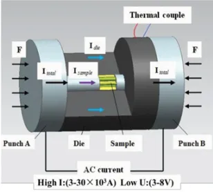
Micro-forming fields activated sintering technology (Micro-FAST) is a creative micro-fabrication method wherein loose powders is directly loaded into mold and then heated by AC current at vacuum atmosphere [1,2]. According to the characteristics of low voltage (3–8 V) and large current (3–30×103 A) demanded by Micro-FAST, the powders system are heated by Joule heat with uniform and rapid heating. Meanwhile, the densification of powder systems are accomplished under the coupling effect of electric field, thermal field and stress field, especially under relatively low sintering temperature at a short time , as shown in Fig. 1. Micro-FAST can be used for fabricating the micro- components with a variety of material systems, for instance, copper, Mn-Zn ferrite and 316L stainless steel [2–6]. It is worth noting that Micro-FAST exhibits many merits, such as low sintering temperature, short sintering time and restraining grain growth, compared to the conventional sintering method.
aCorresponding author:[email protected]
Figure 1. Micro-FAST schematic diagram.
Many studies have shown that the parameters of sintering temperature, heating rates and pressure play a key role in the densification process [7–12]. In fact, the particles of powder are covered by oxides or other contaminants initially, which would affect the formation and growth of neck during the process of thermodynamics and kinetics [13]. For the process of surface-cleaning during field assisted sintering technology, various mechanisms have been proposed. For instances, the plasma activation step efficiently removes impurities and/or oxide layers prior to rapid densification during plasma activated sintering (PAS) [14]. Moreover, in spark plasma sintering (SPS), it is suggested that dielectric breakdown of an oxide film between surfaces of particles induced the surface-cleaning [15–18]. From above discussion, one can see that Micro-FAST is different from SPS [19–21], PAS [22,23] and EDS [24,25], etc., in the heating rates, electric current and applied pressure, so that, it is necessary to study the formation and growth of neck during the Micro-FAST.
In present work, the electrothermal focusing was proposed for explanation of microstructure evolution and surface-cleaning in Micro-FAST, induced by high density of electric filed and thermal field in the contact area of inter-particles. The evidence of surface cleaning mechanism for the fine copper powders is provided by HRTEM image which directly confirmed the cleaning process.
2. Experimental methods
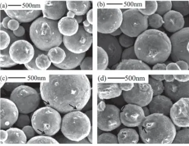
Copper powders with an average particle size of 500nm and a purity of 99.5% were used in Micro-FAST, and Fig.2shows the scanning electron micrographs of the copper powders. The loose powders exhibited good roundness while oxide layer had existed due to ultrafine particles can be oxidized easily and unavoidably, which have an important impact on the densification process.
Figure 3. Microstructure evolution of the fracture morphologies of micro-gear.
at the interfaces between Cu powder particles in the compacts was carried out using a JEM-2010F transmission electron microscope operated at 200 kV.
3. Results and discussion
The characteristic microstructures of copper nanoparticles during Micro-FAST obtained for different sintering stages are shown in Fig.3. One can see that: (1) in the initial stage of Micro-FAST, loose copper nanoparticles were randomly distributed in the graphite mold (Fig.3(a)). The powder system has weak conductivity at this stage under the couple effect of electric field and pressure field; (2) then, plastic deformation was occurred between the inter-particles and the role of electric field became appreciable, as shown in Fig.3(b). The electric current will mainly pass through the powders, and the Joule heat will be generated due to the high contact resistance at the inter-particles; (3) from Fig.3(c), it clearly provided that the coupling of electric field and thermal field between contact particles, indicating that the occurrence of local high temperature between the particles. Correspondingly, the local temperature is sufficient for local melting between copper nano-particles, resulting in the molten copper liquid. The diffusion between the particles, accelerated by the liquid phase, further generated the sintering neck and enhanced the connection, as shown in Fig.3(d).
[image:3.482.146.332.208.352.2]Figure 4. HRTEM images of copper surface cleaning process during Micro-FAST (a) particles rearrangement under the action of pressure at the initial stage (b) oxide layer contacted under the action of pressure (c) oxide layer disappeared at the inter-particle under electrothermal focusing effect (d) with the disappearance of oxide layer, sintering neck is formed.
Figure 5. Whole process of surface cleaning (a) grains rearrangement (b) formation of vacancy (c) migration of vacancy (d) oxide disappeared at the inter-particles.
stress field and residual gas was expelled from the powders by vacuuming while the effect of electric field was weak; (II) formation of vacancy, The elastic, even with plastic, deformation of particles, induced by applied pressure, resulted in the contact of surface oxide-layer and further formed the vacancy between the particles; (III) migration of vacancy, as the particles contact with each other, the large density electric current can induce Joule heating in interfaces of contacted particles, enhancing the migration of vacancy from the boundary to inner of particles. During this stage, the vacancy, full filled with air, would disappear, ascribed to the escape of air; and (IV) enhancement of electro-thermal focusing, with the elimination of the oxide layer, contact resistance between the particles is reduced. The current will directly pass through the grain boundary and generate a large amount of Joule heat, consistent with the description in Fig.3(d).
[image:4.482.156.324.307.425.2]pressure occurs at the beginning, and then with the increase of temperature, the oxide layer was partially broken, resulting in the decrease of contact resistance. This phenomenon further causes local high temperature and liquid phase. And the combination of electric, thermal and stress filed accelerates the diffusion of atoms and formation of neck. The whole process could be confirmed by the HRTEM images. This study provided a clear description of a surface cleaning mechanism through electro-thermal focusing, which is an initial but a fundamental understanding of the mechanism for surface-cleaning in Micro-FAST.
This work was funded in part by the National Nature Science Foundation of China (No. 51275322), the UK Royal Society/China NSFC International Exchanges Programme (No. 51311130134), the Specialized Research Fund for the Doctoral Program Higher Education of China (Grant No. 20130181120118), the China Postdoctoral Science Foundation (Grant No. 2014M552356).
References
[1] D. Lu, Y. Yang, Y. Qin, G. Yang, JMEMS, 22, 1 (2013)
[2] K.L. Huang, Y. Yang, Y. Qin, G. Yang, Int. J. Adv. Manuf. Tech., 69, 2651 (2013) [3] A.K. Du, G. Yang, D. Lu, Y. Yang, Appl. Mech. Mater., 271, 212 (2013)
[4] Y. Zhou, G. Yang, Y. Yang, Y. Qin, D. Yin, Y. Zhang, Adv. Appl. Ceram., 113, 257 (2014) [5] D. Lu, Y. Yang, Y. Qin, G. Yang, J. Mater. Res., 27, 2579 (2012)
[6] K.L. Huang, Y. Yang, Y. Qin, G. Yang, Mater. Manuf. Processes, 28, 183 (2013) [7] D. Siemiaszko, S. Jó´zwiak, M. Czarnecki, Z. Bojar, Intermetallics, 41, 16 (2013) [8] E.A. Olevsky, L. Froyen, J. Am. Ceram. Soc., 92, S122 (2009)
[9] G. Yang, Y. Yang, D. Lu, K.L. Huang, J. Wang, Int. J. Metall. Mater., 19, 1023 (2012) [10] S.K. Jha, R. Raj, J. Am. Ceram. Soc., 97, 527 (2014)
[11] R. Marder, C. Estournès, G. Chevallier, R. Chaim, Scr. Mater., 82, 57 (2014)
[12] R. Muñoz-Moreno, E.M. Ruiz-Navas, B. Srinivasarao, J.M. Torralba, J. Mater. Sci. Technol., 30, 1145 (2014)
[13] K. Yamabe, K.Taniguchi, IEEE J. Solid-State Circuits, 20, 343 (1985) [14] S.H. Risbud, J.R. Groza, M.J. Kim, Philos. Mag. B, 69, 525 (1994) [15] K. Matsugi, T. Hatayama, O. Yanagisawa, Intermetallics, 7, 1049 (1999)
[16] G. Xie, O. Ohashi, M. Song, K. Furuya, T. Noda, Metall. Mater. Trans. A, 34, 699 (2003) [17] R. Chaim, J. Mater. Sci., 48, 502 (2013)
[18] C.S. Bonifacio, T.B. Holland, K.V. Benthem, Scr. Mater., 69, 769 (2013) [19] Z.A. Munir, U. Tamburini, M. Ohyanagi, J. Mater. Sci., 41, 763 (2006)
[21] K. Rajeswari, M.B. Suresh, D. Chakravarty, D. Das, R. Johnson, Int. J. Hydrogen Energy, 37, 511 (2012)
[22] K. Yamazaki, S.H. Risbud, H. Aoyama, K. Shoda, J. Mater. Process. Tech., 56, 955 (1996) [23] S.W. Wang, L.D. Chen, Y.S. Kang, M. Niino, T. Hirai, Mater. Res. Bull., 35, 619 (2000) [24] K.E. Belyavin, D.V. Min’ko, O.O. Kuznechik, J. Eng. Phys. Thermophys., 77, 628 (2004) [25] N. Beri, A. Kumar, S. Maheshwari, C. Sharma, IJMMM, 9, 103 (2011)