DEPARTMENT OF PHYSICS
Investigations of Fast Electron Transport
in Intense Laser-Solid Interactions
by
Mark N. Quinn
A thesis presented in fulfilment of the requirements for the degree of Doctor of Philosophy
This thesis is the result of the author’s original research. It has been composed by the author and has not been previously submitted for examination which has led to the award of a degree.
The copyright of this thesis belongs to the author under the terms of the United Kingdom Copyright Acts as qualified by University of Strathclyde Regulation 3.50. Due acknowl-edgement must always be made of the use of any material contained in, or derived from, this thesis.
Signed:
Date: 29 September 2011
This thesis reports on experimental investigations of relativistic (‘fast’) electron trans-port in solid density plasma. Intense laser pulses, >1019W/cm2, interacting with solid targets generate a front surface plasma from which a mega-ampere relativistic electron beam is created. The transport of this fast electron beam through the target is occluded from direct measurement. Novel diagnostic methods involving proton emission are de-veloped to investigate the effects of magnetic pinching, filamentation and refluxing on fast electron transport.
Results of the effect of self-generated kilo-tesla magnetic fields on fast electron transport in solid aluminium targets are reported. For target thickness of 25µm to 1.4 mm, the maximum energies of protons are measured to infer changes in the fast-electron density and therefore the divergence of the fast-electron beam. If the electron transport was purely ballistic, a much faster decrease in the maximum proton energy with increasing target thickness would be expected. This implies that some degree of ‘global’ magnetic pinching is occurring, particularly in the case of thick (> 400µm) targets. Numerical simulations show that the magnetic pinching effect is significantly reduced in thin targets where enhanced electron refluxing can disrupt the magnetic field growth.
Results of the influence of beam scattering and material resistivity on electron beam filamentation are reported. This phenomena is diagnosed in solids targets ranging from 50−1200µm in thickness using proton beam uniformity measurements. Electron and proton beam uniformity are correlated using a 3D analytical model. In targets of similar initial resistivity, it is found that increasing the target Z (and therefore scattering) produces no measurable effect on electron beam filamentation. Simulations suggest that target resistivity in the low temperature regime and self-induced magnetic pinching are significant influences on beam filamentation in sold targets.
Results of an investigation of fast electron refluxing within solid targets are reported. Refluxing occurs when the fast electrons are reflected by the sheath potentials formed at the front and rear surfaces. The number of times the fast electrons reflux through a Cu fluorescence layer is controlled by varying the thickness of a second layer comprised of plastic (CH). Enhancements in the Kα x-ray yield and source size are measured as
parents
Rose and Frank,
for their support and love,
brothers,
Francis, Liam, Ciar´
an,
who are the easiest of company,
sisters,
Marcella, Linda, Caroline, Mair´
ead, Mary-Rose,
who always inspire,
best friend,
Shane,
who says it as it is,
and partner,
Olivia,
who has made this journey worth-it.
This thesis is the culmination of over three years of research. A number of individuals have made enduring contributions to this experience and are deserving of special mention and appreciation.
First and foremost I wish to sincerely thank my PhD supervisor Prof. Paul McKenna. I am indeed most fortunate to have worked with such an exemplary scientist, a paragon of leadership and professionalism who has consistently provided me with guidance, support and opportunities. I also gratefully acknowledge the funding sources awarded to Prof McKenna by the Science and Engineering Research Council which made my PhD work possible.
From the group at the University of Strathclyde I had the benefit of sharing the ex-pertise of a number of colleagues. A ready forum for discussion on electron transport was provided by Dr Xiaohui Yuan, whose energy and work ethic inspired imitation. Dr David Carroll invariably made time for many prompt discussions and exemplified how the complexities and challenges of an experiment could be managed with patience and efficiency. Also, thanks to my fellow PhD students, Olivier, Silvia, Salima, MP, John and Richard for their comradeship and providing some relief from the toils of long office hours.
By virtue of the collaborative nature of high energy physics research, I had the fortunate experience of working alongside a number of international scientists. These included groups of researchers based at: Queen’s University Belfast lead by Prof Marco Borghesi and Prof Matt Zepf, l’Ecole Polytechnique lead by Prof Julien Fuchs, University of Milan lead by Prof Dimitri Batani, University of Bordeaux lead by Dr. Jo˜ao Jorge Santos, the Beijing National Laboratory lead by Prof Yutong Li, the PHELIX Department at GSI Germany lead by Prof Thomas Kuehl and finally groups based at the U.K’s Central Laser Facility lead by Prof Peter Norreys and Prof David Neely.
The experimental campaigns, conducted at national facilities, involved a number of support staff for whose assistance I am most grateful. Particular mention to the link scientists: Rob Clarke, Margaret Notley and Kate Lancaster at Vulcan Petawatt and Bernhard Zielbauer at Phelix; thank you sincerely for investing a good amount of your energy and many late evenings in helping to bring the experiments online. Thanks also to the dedicated laser technicians at the respective facilities who made each laser shot possible. Special thanks goes to the target fabrication wizards at the CLF for their excellent foils and prompt service. Much deserved appreciation to the engineering support staff at Vulcan, particularly Phil and Toby, for their assistance in tackling the myriad mechanical challenges encountered in a typical experiment.
Computing resources were provided by STFC’s e-Science facility at RAL and also the PCRI computer cluster at the University of Strathclyde. Special thanks to Dr. Alex Robinson in providing access and support to the LEDA numerical code and also to Prof Roger Evans regarding the Pollux code. Other valuable technical support was provided by Dr Ricky Martin and Dr Raoul Trines.
Last but most certainly not least I am indebted to my family, key friends and my partner who have suffered me over these past few years and who are selflessly encouraging even now as I move onwards. Please accept the dedication of this work as modest proof of my heartfelt gratitude.
Role of the author
The author analysed most of the data presented in this thesis, had a leading role in all the experiments and contributed to writing all of the publications resulting from the work presented in this thesis.
Chapter 5: The author played a leading role in both planning and running (as deputy TAO) this experiment. The proton dosimetry film was scanned by L. Lancia during the experiment. Proton stack design and assembly was carried out by the author. Analysis of proton beam maximum energy was carried out by X. H. Yuan. The author con-tributed to the development of the initial sheath size model which was devised by X. H. Yuan. Analytical modelling of ballistic transport was carried out by the author. Hybrid simulations were carried out by both A. P. L Robinson and the author.
Chapter 6: The author played a leading role in both planning and running (as deputy TAO) this experiment. The proton dosimetry film was scanned by L. Lancia during the experiment. Proton stack design and assembly was carried out by the author. Proton beam uniformity analysis was carried out by the author. The 3D proton beam model was written by the author. The LEDA hybrid simulations were carried out by the author assisted by A. P. L Robinson who also ran the ZEPHYROS PIC-Hybrid simulations. The calculation of the resistivity curves for lithium were carried out by M. P. Desjarlais.
Chapter 7: The author played a leading role in both planning and running (as deputy TAO) this experiment. Assembly and the running of the Kα imager diagnostic was
carried out by X. X. Lin who also performed the initial analysis. Further analysis of experimental data was carried out by the author for opacity and absorption effects. The Kα emission and refluxing model was written by the author. The analysis of proton
emission data was carried out by the author including the ballistic model predictions. Hybrid simulations using the LEDA code were carried out by the author, and subse-quent analysis including proton emission predictions. Plasma temperature effects on Kα
emission was also calculated by the author using the FLYCH code.
Publications
1. “On the investigation of fast electron beam filamentation in laser-irradiated solid targets using multi-MeV proton emission.” M. N. Quinn, D. C. Carroll, X. H. Yuan, M. Borghesi, R. J. Clarke, R. G. Evans, J. Fuchs, P. Gallegos, L. Lancia, K. Quinn, A. P. L. Robinson, L. Romagnani, G. Sarri, C. Spindloe, P. A. Wilson, D. Neely and P. McKenna, Plasma Physics and Controlled Fusion, Accepted, to be published December 2011.
2. “Refluxing of fast electrons in solid targets irradiated by intense, picosecond laser pulses,” M.N. Quinn, X.H. Yuan, X.X. Lin, D.C. Carroll, O. Tresca, R.J. Gray, M. Coury, C. Li, Y.T. Li, C.M. Brenner, a P.L. Robinson, D. Neely, B. Zielbauer, B. Aurand, J. Fils, T. Kuehl, and P. McKenna, Plasma Physics and Controlled Fusion, vol. 53, p. 025007, 2011.
3. “Effect of Lattice Structure on Energetic Electron Transport in Solids Irradiated by Ultraintense Laser Pulses” P. McKenna, A. P. L. Robinson, D. Neely, M.P. Desjarlais, D. C. Carroll, M.N. Quinn, X. H. Yuan, C.M. Brenner, M. Burza, M. Coury, P. Gallegos, R. J. Gray, K. L. Lancaster, Y.T. Li, X. X. Lin, O. Tresca, and C.-G. Wahlstr¨om, Physical Review Letters, vol. 106(18), p. 185004, 2011. 4. “Controlling the properties of ultra-intense laser-proton sources using transverse
refluxing of hot electrons in shaped mass-limited targets” O. Tresca, D. C. Carroll, X. H. Yuan, B. Aurand, V. Bagnoud, C. M. Brenner, M. Coury, J. Fils, R. J. Gray, T. Kuehl, C. Li, Y. T. Li, X. X. Lin, M. N. Quinn, R. G. Evans, B. Zielbauer, M. Roth, D. Neely and P. McKenna. Plasma Physics and Controlled Fusion,vol. 53, p. 105008, 2011.
5. “Ballistic Focusing of Polyenergetic Protons Driven by Petawatt Laser Pulses” S. Kar, K. Markey, M. Borghesi, D.C. Carroll, P. McKenna, D. Neely, M. N. Quinn, and M. Zepf, Physical Review Letters, vol. 106(22), p. 225003, 2011.
6. “Hollow microspheres as targets for staged laser-driven proton acceleration,” M. Burza, A. Gonoskov, G. Genoud, A. Persson, K. Svensson, M. N. Quinn, P. McKenna, M. Marklund, and C.-G. Wahlstr¨om, New Journal of Physics, vol. 13, p. 013030, 2011.
7. “Effect of self-generated magnetic fields on fast-electron beam divergence in solid targets,” X.H. Yuan, A.P.L. Robinson, M.N. Quinn, D.C. Carroll, M. Borghesi, R.J. Clarke, R.G. Evans, J. Fuchs, P. Gallegos, L. Lancia, D. Neely, K. Quinn, L. Romagnani, G. Sarri, P.A. Wilson, and P. McKenna,New Journal of Physics, vol. 12(6), p. 063018, 2010.
D.C. Carroll, M. Coury, R.J. Gray, C.M. Brenner, X.X. Lin, Y.T. Li, M.N. Quinn, O. Tresca, and B. Zielbauer, D. Neely, and P. McKenna, Nuclear Instruments and Methods in Physics Research Section A: Accelerators, Spectrometers, Detectors and Associated Equipment, 2010.
9. “Spectral Enhancement in the Double Pulse Regime of Laser Proton Acceleration,” K. Markey, P. McKenna, C. Brenner, D. Carroll, M. G¨unther, K. Harres, S. Kar, K. Lancaster, F. N¨urnberg, M.N. Quinn, A. Robinson, M. Roth, M. Zepf, and D. Neely, Physical Review Letters, vol. 105(19), p. 195008, 2010.
10. “Carbon ion acceleration from thin foil targets irradiated by ultrahigh-contrast, ultraintense laser pulses,” D.C. Carroll, O. Tresca, R. Prasad, L. Romagnani, P.S. Foster, P. Gallegos, J.S. Green, M.J.V. Streeter, N. Dover, C.A.J. Palmer, C.M. Brenner, F.H. Cameron, K.E. Quinn, J. Schreiber, A.P.L. Robinson, T. Baeva, M.N. Quinn, X.H. Yuan, Z. Najmudin, M. Zepf, D. Neely, M. Borghesi, and P. McKenna,New Journal of Physics, vol. 12, 2010, p. 045020.
11. “New developments in energy transfer and transport studies in relativistic laser–plasma interactions,” P. A. Norreys, J.S. Green, K.L. Lancaster, A.P.L. Robinson, R.H.H. Scott, F. Perez, H.-P. Schlenvoight, S. Baton, S. Hulin, B. Vauzour, J.J. Santos, D.J. Adams, K. Markey, B. Ramakrishna, M. Zepf, M.N. Quinn, X.H. Yuan, P. McKenna, J. Schreiber, J.R. Davies, D.P. Higginson, F.N. Beg, C. Chen, T. Ma, and P. Patel,Plasma Physics and Controlled Fusion, vol. 52, 2010, p. 124046. 12. “Laser-Driven Fast Electron Collimation in Targets with Resistivity Boundary,” B.
Ramakrishna, S. Kar, A. Robinson, D. Adams, K. Markey, M.N. Quinn, X. Yuan, P. McKenna, K. Lancaster, J. Green, R. Scott, P. Norreys, J. Schreiber, and M. Zepf,Physical Review Letters, vol. 105(13), p. 135001 2010.
13. “Magnetic collimation of petawatt driven fast electron beam for prospective fast ignition studies,” S. Kar, D. Adams, M. Borghesi, K. Markey, B. Ramakrishna, M. Zepf, K. Lancaster, P. Norreys, A.P.L. Robinson, D.C. Carroll, P. McKenna, M.N. Quinn, X.H. Yuan, C. Bellei, and J. Schreiber, Journal of Physics: Conference Series, vol. 244, 2010, p. 022041.
14. “Fast electron propagation in high-density plasmas created by 1D shock wave com-pression: Experiments and simulations,” J.J. Santos, D. Batani, P. McKenna, S.D. Baton, F. Dorchies, a Dubrouil, C. Fourment, S. Hulin, E. d’Humi`eres, P.H. Nico-la¨ı, L. Gremillet, a Debayle, J.J. Honrubia, P. Carpeggiani, M. Veltcheva, M.N. Quinn, E. Brambrink, and V. Tikhonchuk, Journal of Physics: Conference Series, vol. 244, p. 022060, 2010.
15. “Fast electron propagation in high density plasmas created by shock wave compres-sion,” J.J. Santos, D. Batani, P. McKenna, S.D. Baton, F. Dorchies, A. Dubrouil, C. Fourment, S. Hulin, P. Nicola¨ı, M. Veltcheva, P. Carpeggiani, M.N. Quinn, E. Brambrink, M. Koenig, M. Rabec Le Glohaec, C. Spindloe, and M. Tolley,Plasma Physics and Controlled Fusion, vol. 51, p. 014005, 2009
M. Zepf, and P. McKenna, Comptes Rendus Physique, vol. 10, p. 188-196, 2009. 17. “Observation of the transient charging of a laser-irradiated solid,” K. Quinn, P. a
Wilson, B. Ramakrishna, G. Sarri, L. Romagnani, A. Pipahl, O. Willi, L. Lancia, J. Fuchs, D.C. Carroll, M.N. Quinn, P. Gallegos, X.H. Yuan, P. McKenna, R.J. Clarke, D. Neely, M. Notley, A. Macchi, and M. Borghesi,The European Physical Journal D, vol. 55, p. 293-297, 2009.
18. “Laser-Driven Ultrafast Field Propagation on Solid Surfaces,” K. Quinn, P. Wilson, C. Cecchetti, B. Ramakrishna, L. Romagnani, G. Sarri, L. Lancia, J. Fuchs, A. Pipahl, T. Toncian, O. Willi, R. Clarke, D. Neely, M. Notley, P. Gallegos, D. Carroll, M.N. Quinn, X. H. Yuan, P. McKenna, T. Liseykina, A. Macchi, and M. Borghesi, Physical Review Letters, vol. 102(19), p. 194801, 2009.
19. “Modified proton radiography arrangement for the detection of ultrafast field fronts.,” K. Quinn, P. A. Wilson, B. Ramakrishna, L. Romagnani, G. Sarri, C. a Cecchetti, L. Lancia, J. Fuchs, A. Pipahl, T. Toncian, O. Willi, R.J. Clarke, D. Neely, M. Notley, P. Gallegos, D.C. Carroll, M.N. Quinn, X.H. Yuan, P. McKenna, and M. Borghesi, The Review of scientific instruments, vol. 80(11), p. 113506, 2009. 20. “Effects of front surface plasma expansion on proton acceleration in ultraintense
Contents
Declaration of Authorship i
Abstract ii
Acknowledgements iv
Role of the Author v
Publications vi
Contents ix
List of Figures xiii
List of Tables xvi
List of Symbols xviii
List of Abbreviations xviii
1 Introduction 1
1.1 Fast electron transport . . . 1
1.2 The applications of fast electron transport . . . 3
1.2.1 Fast Ignition approach to ICF . . . 3
1.2.2 Ion acceleration . . . 8
1.2.3 Ultra-fast x-ray science . . . 9
1.2.4 Warm and hot dense matter studies . . . 9
1.3 Thesis overview . . . 10
2 Laser induced plasma and Fast electron generation 12 2.1 Introduction . . . 12
2.2 The laser . . . 12
2.3 The plasma . . . 15
2.3.1 Describing a plasma . . . 16
2.4 Creating the plasma . . . 24
2.4.1 Ionisation . . . 24
2.4.2 Front surface plasma . . . 27
2.5 Energy absorption and fast electron generation . . . 31
2.5.1 An electron in a laser field . . . 31
2.5.2 The ponderomotive force . . . 33
2.5.3 Heating mechanisms - breaking the adiabate . . . 34
2.5.4 Laser to fast electron conversion efficiency . . . 38
2.5.5 Fast electron temperature . . . 41
2.5.6 Fast electron spectrum . . . 43
2.5.7 Injection angle . . . 45
3 Fast electron transport 48 3.1 Current Neutrality . . . 48
3.2 Magnetic field generation . . . 51
3.2.1 Magnetic pinching . . . 53
3.3 Filamentation and instabilities . . . 55
3.3.1 Collisionless Weibel instability . . . 55
3.3.2 Resistive filamentation . . . 58
3.3.3 The ionisation instability . . . 59
3.3.4 Measurements of beam filamentation . . . 60
3.4 Electron beam divergence . . . 62
3.4.1 Measurements of beam divergence . . . 63
3.5 Collisions & Stopping . . . 67
3.6 Target Heating . . . 69
3.7 Sheath fields & refluxing . . . 73
3.8 Target Normal Sheath Acceleration (TNSA) . . . 76
3.8.1 The Mora-Fuchs model . . . 76
3.8.2 Proton beam divergence, source size and emittance . . . 81
4 Methods: Experiments & Modelling 85 4.1 Overview . . . 85
4.2 Experimental facilities . . . 87
4.2.1 Vulcan Petawatt . . . 87
4.2.1.1 Frontend . . . 88
4.2.1.2 The mixed glass amplifiers . . . 89
4.2.1.3 Target area . . . 89
4.2.2 PHELIX . . . 90
4.2.2.1 Frontends and pre-amplifier . . . 91
4.2.2.2 Main-amplification and compression . . . 91
4.3 Diagnostic methods . . . 92
4.3.1 Proton emission . . . 92
4.3.1.1 RCF-stack . . . 93
4.3.1.2 Thomson parabola spectrometer (TP-Spec) . . . 97
4.3.2 The Kα imager . . . 99
4.4 Numerical modelling . . . 102
4.4.1 Hydrodynamic simulations: POLLUX . . . 106
5 Effect of self-generated magnetic fields on fast electron beam
diver-gence in solid targets 109
5.1 Introduction . . . 109
5.2 Experimental method . . . 110
5.2.1 Experimental measurements . . . 111
5.3 Ballistic model predictions . . . 112
5.4 Initial sheath size model . . . 115
5.4.1 Bench-marking the model . . . 117
5.4.2 Model results . . . 118
5.5 Hybrid simulations . . . 119
5.6 Conclusion . . . 124
6 The effects of scattering and low temperature resistivity on electron transport instabilities 125 6.1 Introduction . . . 125
6.2 Experimental Investigation . . . 126
6.2.1 Experimental measurements . . . 128
6.3 Filamented sheath/proton beam modelling . . . 130
6.3.1 Model results . . . 132
6.4 Hybrid simulations . . . 134
6.4.1 The effects of scattering on filamentation . . . 134
6.4.2 The effects of resistivity on filamentation . . . 135
6.5 Conclusion . . . 140
7 Refluxing of fast electrons in solid targets irradiated by intense, pi-cosecond laser pulses 141 7.1 Introduction . . . 141
7.2 Experiment . . . 142
7.3 Refluxing model for Kα emission . . . 145
7.4 Fast electron transport simulations . . . 150
7.5 Proton acceleration results . . . 153
7.6 Conclusion and discussion . . . 155
8 Summary and Conclusions 157 8.1 Summary of results . . . 157
8.1.1 Effect of self-generated magnetic fields: . . . 157
8.1.2 The effects of scattering and low temperature resistivity on elec-tron transport instabilities: . . . 158
8.1.3 Refluxing of fast electrons in solid density plasma: . . . 159
8.1.4 Probing electron transport with proton emission . . . 160
8.2 Implications for an electron transport driver for Fast Ignition . . . 160
8.3 Summary of fast electron transport . . . 161
8.4 Future work . . . 163
A.2 Inertial Confinement Fusion (ICF) . . . 196
B Analytical Models 199
List of Figures
1.1 An illustration providing an overview of fast electron transport. . . 2
1.2 Comparison of Fast Ignition and Central Ignition in terms of gain and compression configuration . . . 4
1.3 Fast Ignition. . . 5
1.4 The temperature-density phase diagram for aluminum . . . 10
2.1 CPA laser chain . . . 13
2.2 Polarisation is defined as the orientation of the electric field relative to incident plane . . . 15
2.3 Resistivity curve for aluminium . . . 23
2.4 Ionisation mechanisms . . . 26
2.5 Schematic of laser-induced plasma at the front of target . . . 29
2.6 Electron trajectories in a linearly polarised electromagnetic field are showed. 33 2.7 A summary of collisionless fast electron heating mechanisms . . . 36
2.8 Measured values of laser to electron conversion efficiency . . . 40
2.9 Measured scaling of fast electron temperature with irradiance . . . 43
2.10 Fast electron energy spectrum . . . 44
2.11 Schematic of injection angle of fast electrons . . . 46
2.12 Injection angle of fast electrons as a function of energyEf0 . . . 47
3.1 The resistivity curve for CH and its effects on fast electron transport . . . 52
3.2 Simulation of fast electron transport in a aluminium target using LEDA . 55 3.3 Illustration of the development of Weibel instability . . . 57
3.4 3D simulations of the resistive filamentation instability . . . 59
3.5 Diagnostic approaches of measuring transverse beam instabilities . . . 61
3.6 Illustration of mechanisms which contribute to electron beam divergence . 62 3.7 Fast electron transport inferred form shadowgraphic measurement . . . . 64
3.8 Fast electron beam divergence measurements . . . 67
3.9 Stopping power for Cu, Al, and CH as a function of fast electron energy . 68 3.10 Degree of ionisation for solid density aluminium versus temperature . . . 70
3.11 The energy loss mechanisms calculated for a 10 MeV electron beam in aluminium withη= 2×10⁶Ω.m. . . 71
3.12 Heating of background plasma by a monoenergetic fast electron beam . . 72
3.13 Simulations of plasma heating for Al and CH targets . . . 73
3.14 Refluxing efficiency versus laser intensity for different target sizes . . . 75
3.15 Acceleration of ions from the rear surface by an electron sheath field . . . 77
3.16 Temporal evolution of rear surface plasma expansion driven by fast elec-trons exiting the target rear surface. . . 78
3.17 Measurements of the expanding ion front at different times probed by
proton deflection . . . 80
3.18 Proton beam divergence . . . 81
3.19 Grooved target and proton beam source size . . . 82
3.20 Proton source size is shown using VULCAN and LULI data . . . 83
3.21 Emittance of proton beam is illustrated . . . 84
4.1 A selection of high energy short pulse laser facilities located in Europe . . 87
4.2 A flow chart description of the VULCAN Petawatt laser chain. . . 88
4.3 A schematic of the PHELIX laser and target area . . . 90
4.4 A schematic of the diagnostic arrangement within the target chamber for a typical electron transport experiment . . . 93
4.5 Proton RCF stack diagnostic . . . 94
4.6 An example of an RCF stack design . . . 95
4.7 Schematic of the modified Thomson ion spectrometer . . . 97
4.8 Example TP-Spec data . . . 98
4.9 The cross-section for the K-shell interaction is shown for copper . . . 100
4.10 A schematic of the Kα imaging diagnostic . . . 101
4.11 Numerical approaches to modelling fast electron transport . . . 102
5.1 Schematic of experimental setup investigating magnetic collimation of electron transport through the target . . . 111
5.2 Maximum proton energy as a function of target thickness is shown for Al foils . . . 112
5.3 Schematic of ballistic model to calculate proton max energy. . . 113
5.4 Ballistic model results for three different injection angle configurations . . 114
5.5 Sheath evolution model . . . 116
5.6 Bench marking of sheath size model using RCF data from a grooved target118 5.7 Bench-marking sheath size model with TP-Spec data . . . 119
5.8 The initial electron sheath size (full-width) as a function of target thick-ness is shown . . . 120
5.9 The divergence of a fast electron beam relative to the injection angle is shown at successive depths in a aluminium target . . . 121
5.10 Fast electron transport simulation results using the LEDA code of mag-netic field for thick and thin targets . . . 122
5.11 LEDA results for fast electron density and temperature at the rear of target123 6.1 Schematic of the diagnostic technique of utilising proton beam emission to probe the uniformity of the rear surface electron sheath . . . 127
6.2 Representative proton beam spatial profiles . . . 129
6.3 The proton beam intensity variation is shown as a function of target thickness for the collective materials . . . 130
6.4 3D Sheath evolution and proton beam model . . . 133
6.5 LEDA simulation output showing the effect of increasing the electron-ion collisional operator . . . 135
7.1 Schematic of experimental setup investigating fast electron refluxing . . . 143 7.2 Experimental measurements of Kα yield and source size . . . 144
7.3 The results from the analytical model of fast electron refluxing in Cu-CH targets . . . 148 7.4 Spatial distribution of Kα emission for 20µm Cu without refluxing (left)
and with refluxing (right). . . 149 7.5 Simulation of electron transport in layered target 20Cu75CH over 2 ps
duration . . . 151 7.6 Hybrid simulation results of fast electron density in Cu layer for different
thickness of CH . . . 152 7.7 Calculated plasma temperature in Cu layer and its effects on Kαemission
are shown . . . 152 7.8 Proton emission measurements for refluxing investigation . . . 154 7.9 The fast electron density on-axis at the target rear surface as calculated
using hybrid simulations is shown. . . 154
8.1 A generalised illustration of the key phenomena investigated in this thesis. 162
List of Tables
2.1 Laser parameters are listed with typical symbols. Example values are quoted for the Vulcan Petawatt laser circa 2008. . . 14 2.2 Scaling of fast electron temperature . . . 42
6.1 List of target materials used for the investigation of beam filamentation . 128
acceleration time ta k-vector k
Alfv´en limit IA laser energy EL
atomic number, charge state Z laser incident angle θL
atomic density na laser wavelength λL
Avogadro’s number NA laser spot radius rL
atomic electric field Ea laser spot diameter φL
Bohr radius aB laser intensity IL
Boltzmann’s constant kB laser frequency ωL
charge density ρq laser power PL
collimation factor Γ laser pulse length τL
collisional frequency νei laser-electron conversion ηL→e
conductivity κ lorentz factor γ
Coulomb logarithm lnΛ magnetic field B
Coulomb potential φ magnetic diffusion time τd
critical density nc mass density ρ
cross section σ mass number A
curl operator ∇× momentum vector p
current density J max proton energy Emax
Debye length λD normalised acceleration time τp
degree of ionisation Z∗ opacity µ
distribution function f particle number N
divergence operator ∇. pedestal intensity Ip
divergence half-angle θ1/2 permittivity of free space εo
electron charge e permeability of free space µo
electron density ne plasma frequency ωp
electric field E plasma scale length Ls
electric field peak E0 plasma skin depth ls
electron mass me ponderomotive force Fp
electron temperature kBTe position vector r
energy E pressure P
energy density proton mass mp
energy gain Q proton source size Dp
fast electron density nf refractive index ηL
fast electron initial energy Ef0 refluxing efficiency ηr
fast electron temperature kBTf resistivity η
fast electron beam radius rf return current density jr
fast electron current density jf scattering angle θei
fast electron current If sheath area SA
fluid velocity vector u sheath diameter De
heat capacity C sound speed cs
impact parameter b speed of light c
injection angle θe stopping power dE/ds
ion mass mi target thickness L
ionisation potential Uk thermal velocity vt
ion density ni vector potential a0
Keldysh parameter K velocity v
List of Abbreviations
AO Adaptive-Optics.
ASE Amplified Spontaneous Emission.
BSI Barrier Suppression Ionisation.
CCD Charged Coupled device.
CH Plastic.
CPA Chirped Pulse Amplification.
CR39 California Resin 39.
CSDA Continuous-Slowing-Down Approximation.
CTR Coherent Transition Radiation.
DT Deuterium-Tritium.
ELI Extreme-Light-Infrastructure.
EOS Equation Of State.
FWHM Full Width at Half Maximum.
GSI Gesellschaft f¨ur SchwerIonenforschung.
HEDP High Energy Density Physics.
HIPER High Power laser Energy Research facility.
HISAC HIgh-Speed Sampling Camera.
ICF Inertial Confinement Fusion.
IFAR In-Flight Aspect Ratio.
LTE Local Thermodynamic Equilibrium.
MCP Multi-Channel Plate.
MHD Magnetic-HydroDynamics.
MPI Message Passing Interface.
NIF National Ignition Facility.
PI Principle Investigator.
PIC Particle In Cell.
PSL Photo-Simulated Luminescence.
RAL Rutherford Appleton Laboratory.
RCF Radio-Chromic film.
RPA Radiation Pressure Acceleration.
SRIM Stopping and Range of Ions in Matter.
TAO Target Area Operator.
TAP Target Area Petawatt.
TCC Target-Chamber-Centre.
TNSA Target Normal Sheath Acceleration.
TP-Spec Thomson Parabola Spectrometer.
VFP Vlasov-Fokker-Planck.
WDM Warm Dense Matter.
Introduction
Over the past 50 years since the first demonstration of the laser [1] there have been continuous efforts to increase and harness its concentrated power to create and study high energy states of matter. The past decades have witnessed the progression to laser intensities beyond the threshold needed for material ionisation and relativistic electron acceleration to current limits where short pulse intensities greater than 1021W/cm2 are attainable.
With such intensities comes the realisation of generating mega-ampere electron beams propagating through dense plasma close to the velocity of light - this is hereafter referred to asfast electron transport. Many novel physical phenomena have become apparent in such conditions. Interesting collective effects such as the generation of 103 tesla magnetic fields and target heating to 107degrees prevail in these most extreme terrestrial environments.
1.1
Fast electron transport
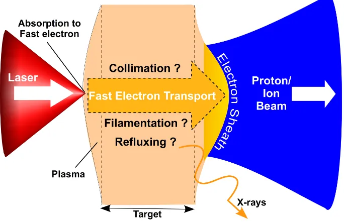
This thesis reports on a number of investigations of relativistic or fast electron transport in solid density plasmas. A simplified schematic of these investigations is shown in Figure 1.1. A petawatt (1015W) class laser is incident onto the front surface of a solid density target. The delivery of this power ionises the target surface creating a dense plasma with a temperature approaching that of the sun’s surface. The short pulsed energy of the laser is coupled into the plasma accelerating a population of electrons to velocities close to that of light. These ‘fast electrons’ are injected into the target forming a beam transporting millions of amperes of current through solid density plasma. Before the advent of sub-picosecond ultra-intense lasers, earlier transport studies in the
Figure 1.1: An illustration providing an overview of fast electron transport. The fast
electron beam is created by the absorption of intense laser energy onto a solid target. The transport of this current through the dense plasma to the rear surface involve key phenomena such as collimation, filamentation and refluxing. These effects are investigated in this thesis using a combination of secondary emission involving protons
and x-rays.
1970’s utilised nanosecond pulsed electron beams injected via a linear accelerator into a preformed low density plasma [2–4].
In the solid density, short pulse regime, much of the specifics regarding fast electron transport physics is occluded from direct measurement by the surrounding high density plasma and the fact that the bulk of the electron beam does not escape the positively charged target. A number of fundamental features of fast electron transport remain open questions and are investigated in this thesis:
1. Can self-generated magnetic fields reduce beam divergence?
Kilo-tesla magnetic fields are expected to be induced by fast electron transport. Al-though these fields have the potential to pinch and help collimate the fast electron beam, the extent to which they influence its transport has yet to be confirmed.
2. What are the main factors controlling beam filamentation?
Electromagnetic instabilities can cause the fast electron beam to break up or fila-ment. In solid density plasma, a number of material properties such as conductiv-ity and atomic number are believed to be contending influences. The dominating dependence remains unclear.
3. To what extent do the fast electrons reflux within thin solid targets?
electrons from escaping the target. The fast electrons have millimeter ranges in solid density material and should therefore be constrained to traverse thin targets a number of times. Direct measurement of such ‘refluxing’ and the effects of such cross propagation have yet to be fully elucidated.
The challenge of probing these concealed ultra fast phenomena is met using the secondary emissions which are generated by the fast electrons. On propagating through the target the fast electrons excite and induce the fluorescence of x-rays from the plasma atoms [5]. At the front and rear surfaces, the formation of electron sheath fields are sufficiently strong to ionise and accelerate beams of protons and other heavier ions away from the target [6]. The spectral and spatial properties of both ion and x-ray emission are very sensitive to the properties of fast electron transport.
The experimental evidence provided by these measurements is interpreted using a com-bination of both numerical and analytical models to provide a description of the fast electron transport physics which can be compared with theory. The resulting picture that emerges from this work is one where all three phenomena - collimation, filamen-tation and refluxing - act collectively on the transport of fast electrons and create a complex inter-dependency.
1.2
The applications of fast electron transport
Fast electron transport intrinsically acts as an efficient energy carrier in coupling the in-tense laser energy to a range of other phenomena. A number of applications utilise this and are currently the primary drives for this field of research. Fusion energy demands plasma temperatures exceeding ten million degrees. Here a relativistic electron beam can provide the necessary heating using a scheme called Fast Ignition [7]. The ion beams accelerated by the fast electron sheath fields can in principle be used as a com-pact oncology source [8]. Short pulsed sources of x-rays and protons provide probes for the study of exotic states of warm dense matter [9, 10] characteristic of many astrophysical systems [11].
1.2.1 Fast Ignition approach to ICF
Figure 1.2: Comparison of Fast-Ignition and Central-Ignition in terms of: expected
fusion energy gain (a) and final compression configuration, which is (b) isochoric for Fast Ignition and (c) isobaric for Central Ignition, described in terms of the fuel density,
ρ, and temperatureTe.
of fuel via lasers or x-rays. Central Ignition is the conventional approach to ICF which requires compression to extreme pressures (1000 g/cm3) to cause the deuterium-tritium fuel to ignite and induce a fusion chain reaction. Fast Ignition is an alternative scheme for ICF that decouples the compression and ignition stages [7]. Utilising distinct stages of compression and heating result in a much greater efficiency and also significantly eases the requirements for ICF when compared to the Central Ignition approach.
In Fast Ignition, the fuel is first compressed to densities ρ≈300−400 g/cm3 and then ignited by an external source. The reduction in compression solves a number of prob-lems. There is no longer a need to ensure perfect symmetry of compression and shock convergence. The lower density fuel means lower driver energies 200−300 kJ rather than
>1 MJ and this results in higher gains. Lowering the constraints of compression means more mass can be assembled to a lower peak density. Greater fuel mass means greater fuel content and thus greater energy output. This again translates into a higher gain for a given laser energy when compared to conventional (central) ignition. This is shown in Figure 1.2(a) which provides a prediction for the performance of Fast Ignition and Central Ignition, if successful. Another distinction concerns the nature of the compres-sion. For Fast Ignition the fuel is compressed to an isochoric state (equal density) rather than isobaric (equal pressure) as is illustrated in Figure 1.2(b-c). This has the advan-tage that the capsule implosion is less susceptible to hydrodynamic instabilities. The capsule design is also distinct with a smaller ratio of capsule radius to shell thickness. This parameter, is known as the In-Flight Aspect Ratio and plays an important role in stabilising the Rayleigh-Taylor instability during the implosion. The smaller IFAR means a more stable implosion compared to Central Ignition.
Figure 1.3: The production of fusion energy by Fast Ignition involves multiple stages
the delivery and transport of the ignitor energy. A laser accelerated beam of electrons [7] or protons [12] are possible candidates. The general sequence of events is depicted in Figure 1.3 for the electron ignitor scheme:
1. Ablation: The compression of the fuel is driven by ablation of the outer layer of the capsule. The ablation is induced by a number of long nano-second pulse laser beams radiating around the capsule surface. A high degree of pulse synchronisation and beam uniformity are required.
2. Compression: The fuel is compressed via the ablation of the outer capsule layer to approximately 300 g/cm3. A total laser energy of 100−300 kJ is needed for this stage.
3. Plasma channel formation: A clear channel must exist to facilitate the deliv-ery of the ignitor laser pulse through the 1 mm scale length plasma surrounding the core. Two possible methods are (i) laser induced hole-boring [13] or (ii) by inserting a gold cone into the fuel assembly [14]. Both methods present significant challenges [15–19].
4. Ignitor laser pulse: At the moment of peak compression, a relatively short pulse laser is injected into the plasma channel. This is the ignitor pulse and it should deliver 100 kJ within 10 ps, that’s 10 PW of power, when stopped in the overdense plasma some few hundred microns from the ignition zone. The focal spot of the ignitor laser should be smaller than the compressed fuel. For a spot radius of 30µm this corresponds to a laser intensity of 3×10²⁰W/cm2.
5. Fast electron generation: The energy of the ignitor laser pulse is absorbed by the plasma and coupled into a beam of fast electrons which are generated over 10 ps and carry a good fraction of the laser energy.
6. Fast electron transport: This fast electron beam must be transported through 100−300µm through compressed plasma spanning a 103 density gradient to the ignition zone. The beam should ideally be spatially smooth and perfectly colli-mated.
7. Fast electron deposition: Collisional stopping of the fast electrons deposits the ignitor energy to the fuel core. The energy distribution of the electron beam determines their range and the efficiency of the energy coupling to the hot-spot. Electrons with energy≈1 MeV have a mean free path close to that of the 3.5 MeV
α-particles produced on the fusion of D and T.
density of≈0.3−0.5 g/cm2. The latter meets the criteria for α-particle stopping 0.25 g/cm2.
9. Burn: A self-sustained fusion burn spreads from this small region throughout the remaining compressed fuel before the fuel disassembles.
The first integrated Fast Ignition experiments with compression beams and cone-guided ignition geometry were performed at scaled down energies by Kodamaet al[20] using the GEKKO XII facility at Osaka University in Japan. These experiments demonstrated increased rates of fusion reactions indicated by an enhanced neutron yield from 104 to 107 when the ignition pulse was delivered. While compression physics have been rigorously developed over the past 30 years for conventional ICF, the physics associated with the generation, transport and energy deposition of the fast electron beam are not well understood and represent the principal challenge facing electron based Fast Ignition [21].
The investigations reported in this thesis, regarding collimation, filamentation and re-fluxing, are fundamentally relevant to the understanding of transport physics in Fast Ignition. For example, the divergence or collimation of the electron beam limits the stand-off distance between the ignition laser pulse and the compressed core. The devel-opment of beam filamentation can incur significant energy losses, therefore reducing the final energy disposition at the core. Refluxing is a feature of fast electron transport in thin foil targets which if not accounted for, can lead to incorrect assumptions of beam transport in relation to Fast Ignition.
Demonstrating Fast Ignition: HiPER
HiPER1 is a European project which aims to define the root to Inertial Fusion energy with a specific objective to develop high gain schemes such as Fast Ignition [22]. As of 2007, the baseline design for HiPER specifies 40×5 kJ laser beam-lines to generate a total of 200 kJ compression energy and 24×3 kJ beam-lines to generate a total of 70 kJ ignitor energy. The compression beams may also be frequency doubled or tripled, the latter puts more power into the target, but is less efficient in converting the light. Much of the specific features of the HiPER system are currently the subject of on-going research, an effort which will eventually produce a point design for the project. HiPER’s preparatory phase concludes in 2013, this is intended to be followed by a 7-year technology development phase.
1
Fast Ignition will require fundamental increases both in repetition rate and efficiency by factors of 10−100 for petawatt type laser systems. Replacing the traditional flash lamps which pump the gain medium with diodes lasers offers a real solution to both problems of efficiency and repetition rate. Part of the HiPER framework is to build a system called PETAL to demonstrate such technology, its goal is to produce 1−10 kJ laser shots up to 10 times per second [23]. This relatively new technology of diode-pumping laser media is currently operating at energies6100 J such as for the MERCURY system at Livermore. The Extreme-Light-Infrastructure (ELI) project is a key European initiative to push the development of a 200 PW laser using diode technology to attain high repetition pulses [24].
If the HiPER facility is built and demonstrates sustained high gain fusion at high repe-tition rates the next step will be to deliver a design for a prototype fusion power plant. This post-HiPER project would include research to address numerous challenges such a system to carry the heat out of the target chamber for electricity production, protecting the device from the neutron flux generated by the fusion reactions, and the production of tritium from this flux in order to produce more fuel for the reactor.
1.2.2 Ion acceleration
Ion emission is one of the key secondary processes resulting from fast electron transport and is described in detail in Section 3.8. The acceleration is the result of intense electric fields setup by the fast electron sheath across the surfaces of the target. The electrostatic potential at the rear surface can exceed 1012V/m and can effectively accelerate ions to multi-MeV energies over a few microns. The acceleration process is known as Target Normal Sheath Acceleration (TNSA) [25]. The geometry of the acceleration mechanism results in ion beams emitted normal to the surface of the target. Key characteristics of these beams include a compact source size both spatially (tens of microns) and tem-porally (ps at source) and very low transverse emittance. Having the largest charge to mass ratio, protons are accelerated more effectively than other heavier ions. At present, the maximum energy of protons accelerated by this method is≈60 MeV [26], although recent reports have been made of 67.5 MeV [27]. The total transfer of energy between the laser ion beam via the fast electrons can reach 10% [26].
250 MeV [8]. While this is currently beyond the range of TNSA methods, the develop-ment of radiation pressure acceleration (RPA) can potentially satisfy these goals [28] . The discrete energy deposition can also be applied to act as the ignitor energy transport in Fast Ignition requiring presently achievable beam energies [12, 29].
Laser accelerated proton beams have also been applied to provide fast heating of sec-ondary solid targets in proof of principle experiments [9, 30] which supports their use as tools for studies of warm dense matter (WDM) and high energy density physics (HEDP). Laser accelerated protons can also be used to probe lower density plasmas [31]. Fur-thermore, the multi-MeV per nucleon energies are sufficient to induce nuclear reactions so that laser systems could be used in nuclear physics experiments as well as medical isotope production e.g for positron emission tomography (PET) [32, 33].
1.2.3 Ultra-fast x-ray science
Hard x-ray Kαsources ranging from 10−100 keV can be produced by relativistic electrons
within solid targets. There are many appealing features of such sources. The x-ray burst is very bright with up to 1013 photons produced per pulse with a short duration close to that of the laser and a small source size depending on the material, target thickness and intensity [34–38]. These features make it an ideal source for fast time resolved x-ray diffraction experiments in optical pump/x-x-ray probe setup and also for bio-medical imaging [39, 40]. Comparatively, the peak spectral brightness of laser produced x-rays is orders of magnitude greater than that from synchrotron sources, although the latter is greater in terms of time-averaged brightness [41].
1.2.4 Warm and hot dense matter studies
Many astrophysical bodies such as the interior of stars, giant planets and brown dwarfs exist in exotic material states. Since the inner workings of astronomical objects are not directly accessible, physical models must be relied upon. Specific densities and pressures can be potentially created and probed by laser plasma experiments which can provide the equation of state(EOS) and opacity measurements necessary for modelling.
Figure 1.4: The temperature-density phase diagram for aluminum (adapted from Lee
et al [42]). The location relevant to Inertial Confinement Fusion conditions is indicated
as ICF.
high density matter. The convergence of these two categories define the area labelled ‘WDM’ for Warm Dense Matter which refers to material states where the ions are strongly coupled Γ > 1 and with partially degenerate electrons. Although a number of theoretical models have been developed, an adequate description of WDM over the whole parameter range is not yet available. The creation of such exotic states of matter in the laboratory provides an important tool for measuring these quantities.
Laser produced plasmas are able to reproduce states similar to those found in stars interior for certain conditions. Fast electron transport provides an efficient means of coupling the laser energy to the heating of target material up to multi-keV tempera-tures [43]. Short pulsed secondary emissions such as proton and x-ray beams produced by fast electrons provide additional means of providing isochoric heating of external samples. These beams can also be utilised to probe the material sample.
1.3
Thesis overview
Chapter 2contains a description of lasers and plasmas individually, progressing to their interaction and culminating in the creation and injection of the fast electron beam into the overdense target. Chapter 3 discusses the transport of this fast electron current within the target and provides a review of progress in this field.
The methodology and results of the investigations regarding fast electron transport are reported in Chapters 4-7 as follows:
Chapter 4: Methods: Experiments & Modelling
Chapter 5: Effect of self-generated magnetic fields on fast electron beam diver-gence in solid targets
Chapter 6: The effects of scattering and low temperature resistivity on electron transport instabilities
Chapter 7: Refluxing of fast electrons in solid targets irradiated by intense, picosecond laser pulses
Laser induced plasma and
Fast electron generation
2.1
Introduction
The focusing of a petawatt of laser power (PL) to a micron scale spot can be achieved
by current laser technology resulting in intensities of over 1021W/cm2. This is several orders of magnitude higher than that required for ionisation of matter. The interaction of such laser intensities with solid targets is discussed in this chapter.
The sequence of events begin with the arrival of an intense sub-picosecond laser pulse onto an initially cold target in vacuum. Within tens of femtoseconds a hot plasma is formed from the ablating front surface which launches shock waves into the target which propagate over nanosecond timescales. The creation of a dense plasma during the life time of the laser pulse results in the coupling of a sizable fraction of the laser energy to the plasma electrons. A large population of electrons are relativistically accelerated by the intense laser fields to propagate into the dense target. The creation of this fast electron current completes this review chapter.
2.2
The laser
The current technological path to producing the highest intensity laser pulses is termed CPA for Chirped Pulse Amplification [44–46], a schematic of CPA is shown in Figure 2.1. The term chirp refers to the process of stretching or compressing the laser pulse length in time. Older technology produced limited laser intensities for the very simple fact that propagating highly intense laser pulses through the laser chain tends to
Figure 2.1: The laser amplification chain incorporating the stretching and compress-ing of the laser pulse for chirped pulse amplification. The final laser pulse which exits
the laser chain is preceded by a low energy pedestal.
damage or destroy the optics and amplifiers. CPA resolves this limitation by stretching the laser pulse before the amplification media. The amplified pulse is then compressed at the end of the laser chain. The chirping is achieved using gratings which spread the different frequencies of the laser pulse out in time, stretching the initial pulse by a factor of 103−105. The gain media amplify the pulse’s energy by a factor of a million or more. Once amplified the stretched pulse is compressed by applying the opposite chirp to that applied by the stretcher. Compressing the pulse in time ramps its power up to the presently achievable levels of 1015 Watts. Compressing the pulse in space with a parabola before target focuses the pulse to a micron size spot creating intensities exceeding 1020W/cm2.
Some fraction, fc, of the total laser energy, EL0, is lost during compression and also from the imperfect reflectivity of the focusing optic. The energy on target is therefore
EL=EL0×fc. Assuming a Gaussian spatial profile for the focused laser spot, the peak intensity on target is usually quoted using the fraction of energy, fs, contained within
the spot (FWHM)φL:
IL=
fs×EL
π(φL/2)2τL
Laser Parameters Symbol Units Vulcan (c. 2008) Energy before compressor EL0 J 600 (max)
Energy on Target EL J 360 (max)
Pulse length (FWHM) τL fs 700
Wavelength λL µm 1.06
Frequency (Angular) ωL Hz 2×10¹⁵
Spot Size (FWHM) φL µm 5
Energy inφL fs % 50
Compressor Throughput fc % 60
Intensity IL W/cm2 1021
Irradiance ILλ2L Wµm2/cm2 1021
Contrast Ratio - - 108
Polarisation p, s - p
Table 2.1: Laser parameters are listed with typical symbols. Example values are quoted for the Vulcan Petawatt laser circa 2008.
where τL is the laser pulse length (FWHM). The relevant laser parameters which are
typically quoted for investigations are listed in Table 2.1.
Producing a single pulse of compressed laser energy is an ideal that is usually unob-tainable in practice. In typical highly intense laser systems the chirped pulse arrives on target amidst a background or pedestal of optical noise termedAmplified Sponta-neous Emission (ASE). As the laser energy is been amplified within the gain media, some leakage occurs which propagates down the laser chain, through the compressor, and arrives on to the cold target some nanoseconds before the main pulse. Gating tech-niques involving Pockel Cells and saturable absorbers can help limit ASE. Although not as energetic as the main pulse, the ASE pedestal is typically nanoseconds long and can deliver sufficient energy to disrupt the target itself. As a figure of merit for intense laser systems, a value relating the intensity Contrast Ratio between the main pulse inten-sity and pedestal inteninten-sity is often used to describes the noise output. The higher the contrast the cleaner the pulse. A contrast of 108 measured at 3 ns before a 1020W/cm2 pulse essentially means a 1012W/cm2 pedestal will arrive on target 3 ns before the main pulse. Besides the ASE pedestal, a sequence of sharp prepulses can also be present. These are the result of spurious reflections and leakage of oscillator pulses through op-tical shutters within the laser chain. Existing over shorter picosecond time scales, the prepulses can be nominally more intense compared to the laser pedestal.
Figure 2.2: Polarisation is defined as the orientation of the electric field relative to incident plane. This is shown for p-polarised and s-polarised electromagnetic fields.
the German ‘senkrecht’ (for perpendicular).
2.3
The plasma
‘A plasma is a quasi-neutral gas of charged and neutral particles which exhibits collective behavior.’ [47]
Solid, liquid and gas are the familiar terrestrial states of matter. The addition of sufficient energy to heat the matter changes its state. At each stage, the additional energy supplied breaks the bonds between the constituent units of crystals (solid), molecules (liquid), or atoms (gas). Further energy can be applied and the atoms of the gas start to ionise, breaking up to their constituents electrons and ions. This is a plasma, the 4th state of matter, discovered in the late 19th century by William Crookes and given its current name by Irving Languir in 1928.
non-vanishing electromagnetic forces on a microscopic scale. In a plasma these fields can only penetrate locally, the rest of the plasma is shielded from their influence. Hence, the plasma is quasi-neutral.
In more technical terms, a set of criteria can be used to define a plasma [47]:
1. The shielding distance is much less than the dimension of the system.
2. A large number of particles must exist within the shielding distance.
3. The rate of collisions is small compared to the plasma oscillation frequency.
The third condition discriminates between a plasma and an ionised gas. In the case of a weakly ionised gas jet the charged particles collide so frequently with the neutral atoms that their motion is described by ordinary hydrodynamic forces rather than electromag-netic forces.
2.3.1 Describing a plasma
The two basic quantities that describe a plasma are its free electron density (ne
[/m3]) and temperature. The latter is written as Te when measured in Kelvin [K] or
written as kBTe when measured in units of energy such as Joules [J] or electron volts
[eV] (1 eV = 1.6×10⁻¹⁹J≈104K). Later in this chapter a sub-population of the plasma electrons representing fast electrons will be described usingnf andkBTf for their density
and temperature respectively.
The number of free electrons per given volume is a function of thedegree of ionisation
of the plasma. This can be calculated using an analytical model presented in Appendix B. With large numbers of particles, statistics are applied to describe their motion. Here the concept of temperature is used to define the mean kinetic energy of the collection of plasma electrons.
Consider an example relevant to solid density plasma at a temperature of a few hundred eV. The electron density created in the ionisation state is given by:
ne=Z∗ni=
Z∗NAρ
A (2.2)
Using a solid density aluminium plasma as an example: the plasma temperature is ≈
200 eV and the atoms have been ionised to an effective ion charge ofZ∗ = 9. The electron density can be calculated with the values for material density ρsolid = ρ = 2.3 g/cm3,
ne = 5×1029/m3. As a comparison, the sun’s corona has an average temperature of
≈0.5 eV and a density of≈1016/m3. Evidently, the conditions of a typical solid density plasma exceed those of the suns atmosphere, although conditions at the star’s core are much more extreme (ncore= 1032/m3 and kBTcore≈keV).
The energetic electrons of a plasma will be pushed away from the heavier ions, creating a charge separation field which pulls them back. The electrons overshoot their equilib-rium positions and oscillate back and forth in a simple-harmonic motion with plasma frequency:
ωpe =
s e2n
e
εo¯γme
(2.3)
where e is the electron charge, ε0 is the dielectric constant, ¯γ is the Lorentz factor of the electrons averaged over one oscillation period and me is the electron mass. As an
example, non-relativistic plasma electrons with density ne = 5×1029/m3 will oscillate
atωpe ≈1016Hz.
The shielding distance describes the thickness of plasma through which the electric fields can penetrate. This is also referred to as the Debye length, given by:
λD =
r
ε0kBTe
nee
(2.4)
written here for the case of static ions and kBTe in units of eV. The plasma electrons
shield out the electrostatic Coulomb potential, φ, of a charge, q, exponentially with distance,r:
φ(r) = q 4πε0r
exp
− r
λD
(2.5)
such that only particles within a distance of λD will interact strongly with the charge.
Beyond this scale, the plasma can be considered electrical neutral. As the electron tem-perature increases, the shielding becomes less effective and the fields penetrate through more plasma. For a perfectly conducting plasma, the depth to which the fields can penetrate is referred to as the collisionless skin depth c/ωpe which is of the order of
nano-metres for hot solid density plasmas. For the example of solid density Al plasma (kBTe = 200 eV and ne = 5×1029/m3), field penetration is therefore minimal with
λD ≈ 0.1 nm. However, at the vacuum boundaries of such a plasma the local density
can be much lower and hence the fields can penetrate to greater depths withλD ≈µm.
Kinetic and Fluids Models
The most direct method to describe plasma phenomena is to solve the equation of motion for every single particle. With well over 1015 particles, solving in this manner at successive intervals would be quite time consuming. However, in thekinetic theory
of plasmas the calculations are performed instead on a statistical distribution function
fα representing a particle species α with momentum p or velocity v (where α = e, i
denotes electrons or ions) at each spatial pointrover time: fα(r,p, t). Hence, the large
number of particles are represented by a single distribution function which enables the large complex system to be modelled.
TheVlasov-Fokker-Planckequation calculates the changes offαat each spatial point
(∂r) over time (∂t) as a function of the forces acting on the particle distribution based on Boltzmann’s equation:
∂fα
∂t +v. ∂fα
∂r +qα[E+v×B]. ∂fα
∂p =Cee(fα) +Cei(fα) (2.6)
whereqα is the charge of speciesα. The forces here are the electromagnetic (E,B) and
the collisional termsCeiandCeeare the Fokker-Planck electron-ion and electron-electron
operators respectively. For a sufficiently hot plasma, collisions can be neglected. For a collisionless plasma, Equation 2.6 reduces to the Vlasov equation:
∂fα
∂t +v. ∂fα
∂r +qα[E+v×B]. ∂fα
∂p = 0 (2.7)
The Vlasov equation, coupled with Maxwell’s equations to solve the fields, provides a closed system for describing a plasma. However, this is a classical system where ionisation and recombination are neglected. In real laser-solid interactions both quantum degeneracy and strong-coupling effects may be important at temperatures below a few hundred electron-volts.
A further simplification, using a hydrodynamic approach, can be applied if the elec-tron dynamics need not be resolved. This method treats the plasma as a fluid of charge, with velocity uα, and the motion of the macroscopic fluid elements are tracked. The
fluid equations are derived from the Boltzmann equation by integrating over the veloc-ity distribution fα(v). The hydrodynamic equations consist of the fluid continuity
equation:
∂nα
∂t + ∂
and the fluid force equation, which is obtained after first multiplying the Boltzmann equation by the momentum before integrating:
nα
∂uα
∂t +
uα·
∂uα
∂r
= nαqα
mα
E+uα×B
c
− 1
mα
∂pα
∂r (2.9)
An equation-of-state is required to close the system of equations. In many cases, it is sufficient to specify the ideal gas law equation of state constant temperature with pressure:
P =nαkBTα (2.10)
If the considered process is slow enough for the species to thermalise then an isothermal equation of state is assumed. Otherwise an adiabatic equation of state is used. The kind of equation of state to be used for each species depends on the comparison of the plasma frequencyωpαand the wave-number kof the phenomenon under study with the
particle thermal velocity:
vtα=
p
kBTα/mα (2.11)
Such that when ωpα/k vtα the particles have enough time to thermalise the plasma
causing a constant temperature. Otherwise the adiabatic equation of state is applicable for a plasma of ddimensions:
P
n
d+2 d
α
= constant (2.12)
The fluid equations, augmented with the equation of state and coupled to Maxwell’s equations, constitute a closed set.
The fieldsE andBare calculated usingMaxwell’s equationsinvolving divergence∇·
and curl ∇×operators.
Gauss’s law for electric field generation by charges:
∇ ·E= ρq
ε0
(2.13)
Gauss’s law for magnetic field generation by charges:
∇ ·B= 0 (2.14)
Faraday’s law for electric field generation by induction:
∇ ×E=−∂B
Amp`ere’s law for magnetic field generation by induction:
∇ ×B=µ0J+ 1
c2
∂E
∂t (2.16)
where µ0 is the vacuum permeability, ρq is the total charge density and J is the total current density.
The fluid theory is sufficiently accurate to describe many important physical processes, and has the great advantage of leading to simpler equations to be solved in compari-son with the kinetic approach. For instance, the main features of the propagation of electromagnetic waves in a plasma can be understood within a fluid treatment. The ki-netic approach on the other hand is necessary in some cases as the fluid approximation may break down, while in other cases provides complementary information which cannot be retrieved within the fluid theory. Systems that are not in local thermodynamic equilibrium (LTE) cannot be described by fluid equations as no equation of state is valid. For example, some of the collisionless laser absorption mechanisms that will be presented later have an intrinsic kinetic nature.
Collisions and resistivity
Any electric field existing within the plasma will drive charged particles as a current. Since the ions are less mobile, this current can be assumed to be entirely electrons. As the electrons are driven through the plasma they suffer collisions. The resistivity within the plasma arises due to the exchange of momentum that occurs when plasma particles collide. Since momentum transfer is dominated by collisions between particles of different mass, one only needs to consider electron-ion collisions. An expression for the resistivity may be obtained by considering the plasma as a fluid of electrons and ions. The change in the momentum of the electron fluid due to collisions with ions is:
∆pei=mene(ve−vi)νei (2.17)
whereνeiis the frequency of electron-ion collisions and is defined later in Equation 2.27.
As the collisions are essentially the interaction of the Coulomb charge of the ions (eZ) and electrons (e) then the momentum transfer is proportional to the relative charges, the densities and the relative velocities of the two fluid species:
∆pei∝Ze2×ne2[ve−vi] (2.18)
The proportionality constant, η, is called the resistivity and can be defined using Equations 2.17 and 2.19 as [47]:
η= meνei
Znee2
(2.20)
The Coulomb forcebetween the electron and ion over distance r is:
Fei =−
Ze2
4πε0r2
(2.21)
and is exerted over the time that the electron is within the vicinity (b) of the ion:
t≈b/ve. Therefore, the change in the electrons momentum is approximately:
∆pei =|Feit| ≈
Ze2
4πε0bve
(2.22)
The Coulomb collision, as an inverse-square law force, deflects the electron in a hyper-bolic trajectory. The scattering angleθei is described by the distance of closest approach
called theimpact parameter (b):
tanθei 2 =
Ze2
4πε0meve2b
(2.23)
In many situations in plasma physics, the upper limit on b is taken to be the Debye length, and the low cut-off is chosen to be the impact parameter for a 90◦ scatter, b0. For such a 90◦ interaction, tan(θei/2) = 1, and the change in momentum will be of the
order of:
meve=
Ze2
4πε0b0ve
(2.24)
and the impact factor here is:
b0 =
Ze2
4πε0meve2
(2.25)
The Coulombcross section is therefore:
σ =πb20 = Z 2e4 16πε2
om2eve4
(2.26)
and the collision frequency is:
νei =neσve =
neZ2e4
16πε20m2
eve3
(2.27)
and finally the resistivity is:
η = me
nee2
νei=
Ze2
16πε2 0meve3
For the case of a Maxwellian distribution of electron velocities, the electron temperature is kBTe = ve2me, which provides an order of magnitude estimate for resistivity and
temperature:
η≈ Zπe
2√m
e
(4πε0)2kBTe3/2
(2.29)
This equation for resistivity is of course based exclusively on large angle collisions. In reality, the long range nature of the Coulomb force makesblarge resulting in small scat-tering angles θei. Indeed the overall effect of many small angle deflections proves more
influential in determining the angular distribution. A correction factor is applied called the Coulomb logarithm, lnΛ, where Λ is the ratio of the maximum and minimum impact factors, Λ = bmax/bmin. These values are usually bmax = λD and bmin = b0 which are defined in Equations (2.4,2.25) respectively and combine to give [48]:
ln Λ = ln 4πneλ3D
= 6.6−0.5 ln
ne
1020/m3
+3 2ln
kBTe
eV
(2.30)
As an example for a hot (200 eV) dense aluminium (5×1029/m3) plasma this expression gives a value of lnΛ≈3. However, for an initially cold solid density plasma, the Coulomb logarithm can be very small or even negative. Quantum mechanical effects, such as degeneracy, need to be included for such conditions, and predictions by Lee and More [49] result in ln Λ ≥ 2. Incorporating this correction factor (ln Λ) the value of η is termed theSpitzer resistivity [50]:
η≈ Zπe
2√m
e
(4π0)2kBTe3/2
lnΛ (2.31)
The expression defines the high temperature resistivity of a fully ionised plasma, at a few hundred eV, referred to as the Spitzer regime and is regularly written as,
ηs= 5.2×10⁻⁵
ZlnΛ
kBT
3/2
e
(2.32)
which exhibits a dependence with plasma temperature and ion charge yet is independent of the plasma density. Since in this modelne=ni, any increased in plasma density will
be accompanied by an increase in frictional drag with ions. These two effects cancel resulting in a constant resistivity. A simple estimate for the current density, j, driven by an electric field, E, in the plasma is given by Ohm’s law:
E=ηj (2.33)
Figure 2.3: Resistivity curve for solid density aluminium [52] composed of measured
data up to≈100 eV [51] extended to higher temperatures by using the Spitzer resistivity prediction [50].
pulse laser and the plasma temperature was characterised via the reflected pulse. The expansion velocity and hence the resistivity was derived from the measured Doppler shifting of the reflected pulse. The trend in resistivity increases up to a saturation value corresponding to the minimum electron mean free path (equivalent to the inter-atomic distance) followed by a decrease with higher temperatures. Davieset al[52] determined a resistivity curve for aluminium from a fit to the Milchberg measurements and extending to the Spitzer regime:
ηAl =
1 5×10⁶(k
BTe)−1+ 170(kBTe)3/2+ 3×10⁵
Ω.m (2.34)
The resistivity equation exhibits a kBTe−3/2 dependence. This inverse relationship
in-dicates that as the plasma is heated the Coulomb cross section (σ) decreases and the resistivity drops rapidly with temperature. Heating can be simply achieved by passing a current through the plasma using ohmicI2R(orj2η) losses. However, heating in this manner cannot proceed indefinitely. Due to the kBT
−3/2
e scaling, continuous heating
to thermonuclear temperatures (tens of keV) becomes progressively more difficult since plasmas as such temperatures become such good conductors that they are considered collisionless - i.e. zero resistivity. At such temperatures the distinction in resistivity between different materials becomes negligible.

![Figure 1.4: The temperature-density phase diagram for aluminum (adapted from Leeet al [42])](https://thumb-us.123doks.com/thumbv2/123dok_us/1687193.122097/30.596.177.457.90.367/figure-temperature-density-phase-diagram-aluminum-adapted-leeet.webp)


![Figure 2.3: Resistivity curve for solid density aluminium [52] composed of measureddata up to ≈ 100 eV [51] extended to higher temperatures by using the Spitzer resistivityprediction [50].](https://thumb-us.123doks.com/thumbv2/123dok_us/1687193.122097/43.596.174.452.95.311/resistivity-aluminium-composed-measureddata-extended-temperatures-spitzer-resistivityprediction.webp)


