Elgamel, Sherif A.E.H. and Soraghan, J.J. (2010) A new fractional Fourier transform based monopulse
tracking radar processor. In: IEEE International Conference on Acoustics Speech and Signal Processing
(ICASSP), 2010 , 14-19 March 2010, Dallas.
http://strathprints.strath.ac.uk/
26217
/
This is an author produced version of a paper
presented at IEEE International Conference on
Acoustics Speech and Signal Processing (ICASSP), 2010 , 14-19 March 2010, Dallas
.
This version has been peer-reviewed but does not include the final publisher proof corrections,
published layout or pagination.
Strathprints is designed to allow users to access the research output of the University of
Strathclyde. Copyright © and Moral Rights for the papers on this site are retained by the
individual authors and/or other copyright owners. You may not engage in further
distribution of the material for any profitmaking activities or any commercial gain. You
may freely distribute both the url (
http://strathprints.strath.ac.uk
) and the content of this
paper for research or study, educational, or not-for-profit purposes without prior
permission or charge. You may freely distribute the url (
http://strathprints.strath.ac.uk
)
of the Strathprints website.
A NEW FRACTIONAL FOURIER TRANSFORM BASED MONOPULSE TRACKING
RADAR PROCESSOR
Sherif A Elgamel and John Soraghan
Department of Electronic and Electrical Engineering, University of Strathclyde
phone: + (44) 1415482514, e-mail:
[email protected], [email protected]ABSTRACT
Conventional monopulse radar processors are used to track a
target that appears in the look direction beam width. The distortion produced when additional targets
appear in the look direction beam width can cause severe erroneous outcomes from the monopulse processor. This leads to errors in the target tracking angles that may cause the target tracker to fail. A new signal processing algorithm is presented in this paper that is based on the use of optimal Fractional Fourier Transform (FrFT) filtering to solve this problem. The relative performance of the new filtering method over traditional based methods is assessed using standard deviation angle estimation error (STDAE) for a range of simulated environments. The proposed system configurations with the optimum FrFT filters succeeds in effectively cancelling additional target signals appearing in the look direction beam width.
Index Term- Interference cancellation, Optimum fractional filter, Monopulse processors
1. INTRODUCTION
A typical monopulse processor for phased array radars is obtained by appropriately phasing the individual array channels to obtain sum and difference outputs. The ratio of the difference-to-sum outputs provides the measure by which the angle offset from the beam axis (i.e. look direction) is determined. The updated angle measurement is used to realign the beam axis with the target. The monopulse radar is repeated N times (N equal to the number of array antenna elements). Thus each antenna will have its own complete receiving system and all the output data will be processed in only one monopulse processor.
Monopulse radars are commonly used in target tracking as they provide superior angular accuracy and less sensitivity to fluctuation in the radar cross section (RCS) of the target compared to other types of tracking radars. However, monopulse radars are affected by different types of interference which affects the target tracking process and may lead to inaccurate tracking [1]. When more than one target exists in the monopulse radar half power beam width the resultant distortion due to this interference will affect the induced target error voltage and consequently the radar tracking ability. Seliktar [2] suggested adding more constraints to the monopulse processor to cancel the distortion effect due to the 2nd target appearing in the look direction however this would require knowledge of the
t t0=
f t1=
t t2=−
f t3=−
a t
1
+
a t
2
+
a
[image:2.612.351.517.186.310.2]t ta+3
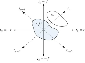
Fig 1- Signal separation in the th
a domain
position of the 2nd target. In our work we propose the use of an optimal fractional Fourier transform filter to cancel a 2nd additional target signal that appears in the look direction main beam without adding any more constraints to the monopulse processor. Following a brief introduction to the Fractional Fourier Transform (FrFT) the paper will describe the structure of the new FrFT based monopulse radar processor. The superior performance of the new algorithm will be demonstrated for multiple targets.
2. FRACTIONAL FOURIER TRANSFORM
The FrFT is the generalized formula for the Fourier transform that transforms a function into an intermediate domain between time and frequency. The signals with significant overlap in both the time and frequency domain may have little or no overlap in the fractional Fourier domain as illustrated in Fig 1. The signals S1and S2can be separated
in the FrFT domain using an ordera.
The fractional Fourier transform of an arbitrary functionx(t), with an angleα, is defined as [3]:
³
∞∞ −
= xt K tu dt u
Xα( ) () α(, ) (1)
where Kα(t,u) is the transformation Kernel and α =aπ/2 with a∈ℜ. Kα(t,u)is calculated from [4]:
° ° ° ¯ °° ° ®
+ +
− −
=
− +
π π
α δ
π α
δ
π α
π
α α α
α
2 )
(
2 )
( 2
cot 1
) , (
csc cot 2
2 2
of muliple a is if u
t
of multiple a is if u
t
of multiple a not is if e j
u t K
jut u t j
) (t s ) (t c
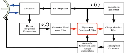
Fig 2- New strucure of the proposed monopulse radar
The optimum value for a for a chirp signal to represent the signal in the optimum FrFT may be written as [5]:
) 2 ( tan 2 1 t f aopt δ γδ π × − = − (3)
where δf is the frequency resolution, δtis the time resolution, and γis the chirp rate parameters. Eq (3) can be used to either calculate the optimum FrFT order or to estimate the chirp rate of a signal for a given FrFT order.
3. MONOPULSE RADAR PROCESSORS
A conventional monopulse radar processor is a non adaptive system comprising two sets of weights set to the sum and difference steering vectors, respectively [6]:
) ( l
a
w¦ = ν ,
l a w ν ν ν ∂ ∂ = Δ ) ( (4)
where a(ν) is the centre phase normalized [1×N] steering vector in the look direction, Nis the number of antenna, νis the spatial steering frequency. The sum and difference outputs are given in terms of the respective processors,
) ( ) (l w l
z¦ = ¦x , zΔ(l)=wΔx(l) (5) where x(l) is the N×1 spatial snapshot at time instant l. The real part of the ratio of difference to sum outputs is known as the error voltage defined as [6]
¿ ¾ ½ ¯ ® ℜ = ¦ Δ ) ( ) ( ) ( l z l z l ν ε (6)
This error voltage conveys purely directional information that must be converted to an angular form via a mapping function.
A spatial processor is an adaptive system comprising an adaptive sum and difference beams formed by applying sum and difference unity gain constraints in the look direction, the sum and difference weights may be written in the following form [6]:
Σ − Σ Σ − Σ= v R v v R w x H x 1 1 , Δ − Δ Δ − Δ = v R v v R w x H x 1 1 (7)
where Rx is the covariance matrix of the input data, ν¦and
Δ
ν are the spatial steering frequency for the sum and difference channel respectively.
4. FRFT BASED MONOPULSE RADAR
PROCESSOR
In the proposed new FrFT based monopulse radar illustrated
in Fig 2, a new FrFT filtering block is introduced as shown in red. A pulsed chirp signal c(t) is produced from the waveform generator. ) ) 2 )( ( exp( )
( t T 2
T F F j t
c stop start
− −
= π (8)
where t is the time, Tis the chirp time duration (pulse duration), Fstart is the chirp start frequency, and Fstop is the
chirp stop frequency. This is up-converted to the radar carrier frequency, amplified and passed through the duplexer to be transmitted. The down-converted received signal passes through a band limited Gaussian filter (nominal value is 200 KHz). The received signal s(t)may be expressed in the baseband as: °¯ ° ® + < < × = − − − − where else T T t T F F e e A t
s d start start
T T t T F F j j start start stop o 0 ] . ) [( ) ( 2 ) 2 )( ( 2 φ π πφ (9)
where A is the received signal amplitude, φois a random
phase shift, and Tstartis the start time of the returned pulse,
passes through a band pass Gaussian filter. The start time
start
T depend on the target range Rtand is determined from:
8 10 3 2 × × = t start R T (10)
The Doppler shift and delay effect on the target chirp signal is determined by the dot product of the chirp signal by the Doppler vector Fd defined as:
) ) ( 2
exp( d start
d j f t T
F = π − (11)
where fdis the target Doppler frequency.
For the phased array receiving antenna, the antenna phase factor Fφis introduced by
) ) (
2
exp( j f T t
Fφ = − π c start−N×Δ (12)
where Nis a vector represented as 0:N−1, and Δtis calculated from 8 10 3 sin × × =
Δt D φt
(13)
where Dis the separation between the antenna elements, φt
is the target angle from the antenna bore sight.
As seen in Fig 2 the optimum fractional filter obtains information about the shape of the chirp signal from the waveform generator and the updated target range from the range calculation. This information is used to determine the optimal FrFT order. The output from the FrFT filter is passed to the matched filter where the target parameters are computed.
The optimal FrFT filter consists of Nreceiving channel in which the received signal from each of the Nantenna elements will fill L range gates. The total radar data size is therefore equal to N×L for each pulse return. The optimum FrFT domain is calculated for each receiving channel data with size1×L to filter the signal in the fractional domain. The resultant filtered data (useful signal) is converted back from the optimum FrFT domain using inverse FrFT processor to the time domain. The 1×L data output from N
FrFT processors are applied to the monopulse processor to determine the target information parameters.
The following steps are involved in the proposed algorithm that may be used to cancel the 2nd target signal arriving in the look direction of the main beam while extracting the 1st target signal:
1. Determine the optimal fractional domain for the 1st target signal.
2. Calculate the correlation matrix for both targets. 3. Calculate the cross correlation matrix for the 1st and
2nd and the auto correlation matrix of the 2nd target in the optimum FrFT domain.
4. Design the optimum filter in the fractional domain. 5. Extract the useful signal for the 1st target by using
the optimum fractional transform matrix.
6. Transform the useful signal to time domain by using the inverse FrFT with known optimal order. The mathematical description for the steps is now described. A signal model of our radar system [3] is:
y x
z= + (14)
where the useful signal x is the 1st target signal and the distortion signal yis the 2nd target.
The target received signal is a chirp signal given by Eq 9. The optimum FrFT order aopt for this chirp can be computed
by applying Eq 3 to the radar system as:
) ) (
( tan
2 2
1
L F F
T F a
start stop
s opt
× −
× −
= −
π (15)
where Fs is the sampling frequency.
The required information to calculate correlation matrices is obtained from the fact that we have previous knowledge of the target position (already tracked before the 2nd target enters the radar look direction) from the sample signal of the waveform generator (parameters of the transmitted chirp signal). So Rxxis computed as:
) ( H
xx E
R = x.x (16)
where xis the chirp signal of the 1st target at range Rt: )
( t
x×c R
Φ =
x (17)
where Φx is a random phase shift similar to that used in Eq 9 defined as :
) 2
exp( x
x= − jπ×φ
Φ (18)
and ) )
2 )(
( exp( )
( T 2
T t T
F F j R
c stop start n start
t − −
−
= π (19)
where Tstartis calculated from Eq 10 and is due to a target
existing at Rt.
Similarly Ryy is calculated from:
) ( H
yy E
R = y.y (20)
where y is the chirp signal at the 2nd target range:
) ( t t
y×c R +ΔR
Φ =
y (21)
where ΔRtis the maximum range difference between the two targets that can’t be resolved by a range gate canceller. ΔRt can also be considered as the number of range bin occupied
by the 1st target. ΔRt in Eq 21 is used because there is not any information about the range of the 2nd target. Φy is
another random phase shift is calculated from: ) 2
exp( y
y = − jπ×φ
Φ (22)
The next step is to calculate the cross correlation matrix
a ay
x
R for the 1st and 2nd targets and the auto correlation matrix
a ay
y
R of the 2nd target in the optimum FrFT domain by applying [7]
opt opt
a a
a H xx a
y
x F R I F
R = − (23)
opt opt
a a
a
yy H xx a
y
y F IR I R F
R = ( + ) − (24)
Then the filter in the optimum FrFT domain gopt,j is given by
L .., 1,2, j j j R
j j R g
a a
a a
y y
y x j
opt = = …
) , (
) , (
, (25)
The filtered signal x′ in the time domain is introduced by: z
x a
g
a F
F Λ
=
′ − (26)
where Λgis a diagonal matrix whose diagonal consists of the
elements of the vector gopt,j.
All the outputs signals from theN FrFT filters are then passed to the matched filter and then supplied to the monopulse processor (illustrated in Fig 2) to calculate the target information parameters using Eqs 4-7 that were described in section 3.
5. SIMULATION RESULTS
The simulations comprise an array of 14 elements spaced 1/3 meters apart. The radar pulse width is 100 microseconds and the pulse repetition interval of 1.6 milliseconds for a 435 MHz carrier. A 200 kHz Gaussian band pass filters exists at the front end of each N receiver to filter the incoming data returns prior to sampling. The incoming baseband signals are sampled at 1 MHz. Also it is assumed that the radar operating range is 100:200 range bins with a starting window at 865 microseconds and a window duration of 403 microseconds. The target is considered at range bin=150 at angle o
32 from the look direction with target signal to noise ratio (SNR) set to 50 dB. We consider that the second target has a SNR of 53 dB (double power of 1st target), at an angle that varies randomly near to the 1st target but still in the look direction beam width), and at range bin 153 (so it can not be resolved because the 1st target occupied bins includes bin 7).
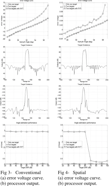
system is completely distorted and the radar can’t track the 1st target. In the case of the spatial adaptive processor in Fig 4 (d), it starts produce good tracking results from 60 dB because of the adaptive characterization of the beam pattern attempting to cancel the 2nd target signal. Despite the low value of STDAE (average value 0.3) it still introduces a high error in the 1st target angle calculation.
Substituting the specific monopulse radar parameters in Eq (15), we get the order of the optimal FrFT domainaoptequal
to 1.7074. Following the steps mentioned in section 6, we calculate the correlation matrix for the 1st target Rxxand
the2nd target Ryyby considering ΔRt= 7 range bin (at more
than 7 range bin there is no problem because the radar can cancel the 2nd target using a rage gate canceller). All the steps in section 4 are continued until the filtered data is produced. The filtered data is passed to the radar processor to calculate the processors outputs using Eq 5. It is seen from Fig 3 (c), and Fig 4 (c) that only one strong target appears in the output and the 2nd target is significantly suppressed (more than 20 dB reduction).
[image:5.612.74.296.313.688.2]As seen in Fig 3 (a) and Fig 4 (a), the resulting monopulse
Fig 3- Conventional (a) error voltage curve. (b) processor output. (c) new processor output. (d) STDAE.
Fig 4- Spatial (a) error voltage curve. (b) processor output. (c) new processor output. (d) STDAE.
curves are nearly identical to their original values. As a result the problem of the distortion due to the 2nd target in the monopulse look direction has been resolved. The resultant STDAE for different SNR (20:100 dB, keeping the previous difference SNR between the two targets) for both the conventional processor and spatial processor shown in Fig 3 (d) and Fig 4 (d) are particularly low (average value less than 0.1). This implies that both processors are able to track the first target correctly and the introduced error due to the existence of the 2nd target is significantly cancelled.
6. CONCLUSION
We have presented a solution for the distortion problem due to a 2nd unwanted target appearing in the monopulse look direction main beam. The proposed system configuration with the optimum N FrFT filters successfully cancels the 2nd target signal and minimizes the STDAE for the both considered monopulse processors. A very high improvement in the radar tracking ability for different SNR (because of very low STDAE) is gained by using the suggested cancelling technique. One of the key advantages of the proposed system is that it will work in an excellent manner when only one target in the look direction (normal case) as well as when more than one target exists in the look direction. Future work will consider a more difficult scenario that in addition to a 2nd target appears in the radar look direction, a jammer will interfere its signal through the radar main lobe and side lobes. Also we will study the system performance when multiple targets exist (more than two targets in the look direction).
7. REFRENCES
[1] S. A. Elgamel and J. J. Soraghan, "Target Tracking Enhancement Using A Kalman Filter In The Presence Of Interference," in Geoscience and Remote Sensing Symposium, 2009. IGARSS 2009. IEEE International, 2009. [2] Y. Seliktar, "Space- Time Adaptive Monopulse Processing." vol. PhD: Georgia Institute of Technology, 1998.
[3] C. Candan, M. A. Kutay, and H. M. Ozaktas, "The discrete fractional Fourier transform," Signal Processing, IEEE Transactions on, vol. 48, pp. 1329-1337, 2000.
[4] H. M. Ozaktas, O. Arikan, M. A. Kutay, and G. Bozdagt, "Digital computation of the fractional Fourier transform," Signal Processing, IEEE Transactions on, vol. 44, pp. 2141-2150, 1996.
[5] C. Capus and K. Brown, "Short-Time fractional fourier methods for the time-frequency representation of chirp signals," The Journal of the Acoustical Society of America, vol. 113(6), pp. 3253-63, 2003.
[6] S. Yaron, B. W. Douglas, and E. J. Holder, "A space/fast-time adaptive monopulse technique." vol. 2006: Hindawi Publishing Corp., pp. 218-218.
[7] A. Kutay, H. M. Ozaktas, O. Ankan, and L. Onural, "Optimal filtering in fractional Fourier domains," Signal Processing, IEEE Transactions on, vol. 45, pp. 1129-1143, 1997.