City, University of London Institutional Repository
Citation
:
Gruppetta, S. and Chetty, S. (2011). Theoretical study of multispectral structured
illumination for depth resolved imaging of non-stationary objects: focus on retinal imaging.
Biomedical Optics Express, 2(2), pp. 255-263. doi: 10.1364/BOE.2.000255
This is the unspecified version of the paper.
This version of the publication may differ from the final published
version.
Permanent repository link:
http://openaccess.city.ac.uk/1508/
Link to published version
:
http://dx.doi.org/10.1364/BOE.2.000255
Copyright and reuse:
City Research Online aims to make research
outputs of City, University of London available to a wider audience.
Copyright and Moral Rights remain with the author(s) and/or copyright
holders. URLs from City Research Online may be freely distributed and
linked to.
City Research Online:
http://openaccess.city.ac.uk/
[email protected]
Theoretical study of multispectral
structured illumination for depth
resolved imaging of non-stationary
objects: focus on retinal imaging
Steve Gruppetta and Sabah Chetty
Department of Optometry and Visual Science, City University London, EC1V 0HB, UK
Abstract: Current implementations of structured illumination microscopy for depth-resolved (three-dimensional) imaging have limitations that restrict its use; specifically, they are not applicable to non-stationary objects imaged with relatively poor condenser optics and in non-fluorescent mode. This includes in-vivo retinal imaging. A novel implementation of structured illumination microscopy is presented that overcomes these issues. A three-wavelength illumination technique is used to obtain the three sub-images required for structured illumination simultaneously rather than sequentially, enabling use on non-stationary objects. An illumination method is presented that produces an incoherent pattern through interference, bypassing the limitations imposed by the aberrations of the condenser lens and thus enabling axial sectioning in non-fluorescent imaging. The application to retinal imaging can lead to a device with similar sectioning capabilities to confocal microscopy without the optical complexity (and cost) required for scanning systems.
© 2010 Optical Society of America
OCIS codes: (110.0180) Microscopy, (170.6900) Three-dimensional microscopy, (180.6900) Three-dimensional microscopy, (170.4470) Ophthalmic optics and devices, (170.4470) Oph-thalmology.
References and links
1. M. A. A. Neil, R. Juskaitis, and T. Wilson, “Method of obtaining optical sectioning by using structured light in a conventional microscope,” Optics Letters 22, 1905–1907 (1997).
2. D. Karadagli´c, “Image formation in conventional brightfield reflection microscopes with optical sectioning via structured illumination,” Micron 39, 302–310 (2008).
3. D. Karadagli´c and T. Wilson, “Image formation in structured illumination wide-field fluorescence microscopy,” Micron 39, 808–818 (2008).
4. M. G. L. Gustafsson, “Surpassing the lateral resolution limit by a factor of two using structured illumination microscopy,” J. Microsc. 198, 82–87 (2000).
5. M. G. L. Gustafsson, “Nonlinear structured-illumination microscopy: Wide-field fluorescence imaging with the-oretically unlimited resolution,” Proceedings of the National Academy of Science 102, 13081–13086 (2005). 6. T. Wilson and C. Sheppard, eds., Theory and Practice of Scanning Optical Microscopy (Academic Press, 1984). 7. S. A. Shroff, J. R. Fienup, and D. R. Williams, “OTF compensation in structured illumination superresolution
images,” Proc. SPIE 7094, 1–11 (2008).
8. S. A. Shroff, D. Williams, and J. R. Fienup, “Structured illumination for imaging of stationary and non-stationary, fluorescent and non-fluorescent objects,” Patent WO/2008/124832, PCT/US2008/059922 (2008).
10. L. Krzewina and M. Kim, “Single-exposure optical sectioning by color structured illumination microscopy,” Optics Letters 31, 477–479 (2006).
11. D. A. Atchinson and G. Smith, Optics of the Human Eye (Butterworth Heinemann, 2000). 12. E. Hecht, Optics (Addison-Wesley, 2002), 4th ed.
13. M. Born and E. Wolf, Principles of Optics (Cambridge University Press, 1999), seventh ed. 14. J. W. Goodman, Introduction to Fourier Optics (McGraw-Hill, 1996), 2nd ed.
15. R. N. Bracewell, The Fourier Transform and its Applications (McGraw-Hill, 2000), 3rd ed.
1. Introduction
Structured illumination microscopy has been proposed and developed as a technique which enables optical sectioning of a three-dimensional (3D) object resulting in images similar to those obtained using a confocal scanning microscope [1, 2, 3]. It has also been used for en-hanced lateral resolution, allowing superresolution beyond the diffraction limit [4, 5]. In the depth-resolving case, the basic principle between structured illumination microscopy and con-focal microscopy is similar, namely that only planes that are in focus are imaged efficiently and out-of-focus planes contribute significantly less to the image. However they are fundamentally different optical systems. Structured illumination microscopy has the advantage of being an optically simple technique that does not require laser illumination nor scanning of the beam or sample. The non-scanning configuration of the structured illumination microscope enables a simple optical set up with minimal moving parts, and thus the potential for cost- effectiveness and robustness. Furthermore, in the confocal microscope the detector pinhole rejects light in order to achieve axial sectioning, and in practice, especially in the ophthalmic imaging case of the confocal Scanning Laser Ophthalmoscope (SLO), trade offs have to be made between pin-hole size and confocality, thus limiting the axial sectioning capabilities of the device. Structured illumination microscopy does not reject any light prior to detection and can therefore image the sample more efficiently.
In structured illumination microscopy, the sample is illuminated with a sinusoidal pattern along one of its lateral dimensions. For weak objects, it has been shown that it is only the zero-order spatial frequency that does not attenuate with defocus [6]. The sinusoidal illumination enables us to recover an image in which the zero-order term is absent; all remaining spatial frequencies will therefore attenuate with defocus ensuring that the in-focus plane is the one that contributes most significantly to the image obtained [1]. However, it is necessary to acquire three successive images with the sinusoidal pattern displaced by phases of 2π/3 and−2π/3 with respect to the first image. From these three images, an optically sectioned image of the sample can be obtained, as well as an image analogous to the conventional microscope for comparison [1, 2, 3].
2. Non-stationary objects and retinal imaging
When dealing with non-stationary objects, such as in retinal imaging where the involuntary and voluntary tremors and saccades of the eye result in a continuously moving sample, the sequen-tial acquisition of the three images with shifted sinusoidal patterns cannot work as the desired phase shift cannot be obtained. A solution has been proposed by Shroff et al. for the applica-tion of structured illuminaapplica-tion for superresoluapplica-tion in which a postprocessing algorithm has been developed to estimate the random phase shifts introduced by a non-stationary object [7, 8, 9].
sectioning was first proposed by Krzewina et al. [10]. In the method described in this Paper, the wavelengths are chosen to match the peak responsivity of the three detector types in a colour CCD camera so that, after appropriate filtering to minimise cross-talk, the three required im-ages can be extracted from the three colour channels of a single image from the CCD camera from which the final optically sectioned image can be retrieved. The resulting multispectral image will of course be a result of three sub-images which are not exactly identical owing to the difference in reflectivity of the imaged layer for the three wavelengths. However, the spatial frequency of the grid will be high with respect to the structures being imaged (as discussed below) and therefore any artefacts will be negligible. Furthermore, in practical situations it is likely that a number of successive optically sectioned images will be aligned and averaged to maximise contrast and minimise noise, and hence the non-stationarity of the object is now ad-vantageous as the averaging process will ensure that the inhomogeneities due to wavelength differences of a single image are also averaged. The final image will therefore be a composite of three wavelengths, yielding more information than a monochromatic image.
When imaging the human retina, standard structured illumination microscopy encounters a further problem that prevents its application to retinal imaging. The structured pattern illumi-nating the sample is achieved in one of two ways, namely grid projection or fringe projec-tion [1, 2, 3]. In the former, a sinusoidal grid is illuminated incoherently and imaged onto the sample, in the latter a laser beam is used to generate a coherent fringe pattern on the sample. It has been shown by Karadagli´c and Wilson that axial sectioning can only be obtained under incoherent imaging [2, 3] and therefore the fringe projection method can only be used for flu-orescence microscopy as the incoherence is obtained through the mutual independence of the fluorofores; non-invasive retinal imaging is not a fluorescence technique and hence fringe pro-jection cannot be used. Grid propro-jection is limited by the Modulation Transfer Function (MTF) of the condenser lens as the spatial frequency of the grid affects the axial resolution. Because of the relatively poor optics of the human eye (which acts as both condenser and objective in reti-nal imaging) the highest spatial frequency that can be obtained by the grid projection technique (about 60 cycles per degree (cpd), this being the frequency cut-off of a typical eye [11]) is too low for achieving the desired axial resolution (which Neil et al. [1] showed to be a maximum when the spatial frequencyν of the grid is given byν=NA/λ, where NA is the numerical aperture of the eye andλ the wavelength, giving approximately 500cpd for a 4mm pupil at 500nm).
The technique proposed in this Paper resolves this issue by introducing a third projection method which is a modified fringe projection method that we will refer to as Fizeau fringe projection technique. The technique, described in detail in the next section, can project fringes whose spatial frequency is not limited by the optics of the eye (or more generally by the collec-tor lens) and illuminates the sample incoherently as required for non-fluorescent axial section-ing ussection-ing structured illumination.
3. Fizeau Fringe Projection technique
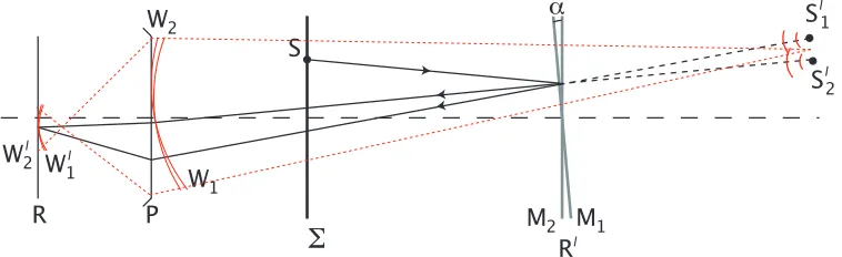
The modified, or incoherent, fringe projection technique is based on a Michelson interferometer set up in which an incoherent extended light source is used to project straight Fizeau fringes directly onto the retina. (We will illustrate this technique with specific reference to the oph-thalmic case though it is applicable to structured illumination microscopy in general.) We will summarise the theory to highlight the nature of the fringes, as this is critical in structured illu-mination microscopy, though further detail can be found in most optics texts [12, 13]. Figure 1 shows a representation of a Michelson interferometer in which all branches are superimposed onto the same optical axis. The planeΣrepresents the extended incoherent light source, M1and
not shown). The axial optical path length of the mirrors from the source is equal, though one mirror is tilted with respect to the other by a small angleα. If we consider a point source S on the extended sourceΣ, then each mirror creates an image of this source, S1and S2 respec-tively. The fringes are localised at the plane of the air wedge produced by the two mirrors, and therefore the eye will focus at the plane containing M1and M2.
Σ
S
M
1M
2R
P
R
lS
l2S
1lW
2W
1W
1lW
2l [image:5.612.118.497.154.270.2]α
Fig. 1. Schematic representation of the Michelson interferometry set up used for the Fizeau fringe projection technique. The schematic superimposes all branches onto the same axis for clarity. The ray shown coming from S will reflect off both mirrors such that the optical path difference of the reflected rays is only dependant on the thickness of the optical air wedge formed by the mirror, for small tilt anglesα. In relation to Fig. 2,Σrepresents the plane of the rotating diffuser, M2is the common reference mirror and M1the wavelength specific mirror. P and R are the pupil plane and retinal plane respectively, representing the eye. The plane containing the mirrors, R, is conjugate to R.
We can therefore consider the light reaching the eye to be coming from the two point sources
S1and S2both of which are emitting diverging spherical waves, so that at the pupil plane of the eye we can define wavefronts W1and W2coming from the respective sources. These wavefronts
have the same curvature since the two sources S1and S2are equidistant from the eye for small angleα, and their respective angular tilt isα. As the eye is focused at the plane containing the mirrors M1and M2, these wavefronts will focus before the retina (as shown by the dotted red
lines in Fig. 1) and we can therefore define two diverging wavefronts W1and W2at the retina that are again identical except for tilt. The interference produced by these wavefronts will therefore form an interference pattern on the retina consisting of parallel straight fringes. It should be noted that becauseα is small, the angular subtense of the sources S1and S2at the eye can be assumed to be well within the isoplanatic patch of the eye, therefore any aberrations introduced at the pupil plane of the eye will be common to both W1and W2, and hence W1and W2. Thus
the fringe pattern produced is not affected by the optics of the eye and the spatial frequency of the sinusoidal pattern is only a function of the angleα and the wavelengthλ [12]. This holds for all point sources S on the extended incoherent source planeΣ, thus giving an incoherently illuminated sinusoidal grid pattern whose spatial frequency can be tuned by rotating one of the mirrors to vary the angleα. The phase of the illuminating sinusoidal pattern can be altered by moving one of the mirrors axially to alter the relative optical path difference between the two branches. By separating the three wavelengths it is possible to adjust the frequency and phase of each fringe pattern separately by using three different mirrors in one of the arms of the interferometer.
retina, the interference pattern produced by the virtual point sources S1and S2due to the actual point source S of the extended sourceΣis only a function of the tiltα. Stated alternatively, the interference at any point on the localisation plane depends only on the thickness of the air wedge at that point, as expected for Fizeau fringes (fringes of equal thickness). For out-of-focus planes this is no longer the case; the interference pattern produced by each point source S onΣ is now also dependant on the location of the point source so that each point source will produce a pattern which has a slight phase shift with respect to its neighbour. As a result the pattern is now dependant on the effective size of the extended source and the distance of the source from the mirrors. The aperture of any detection system (such as the eye) will also impact on the effective size of the source. Therefore in general, the modulation of the fringes will decrease with increasing defocus but the rate of change of the modulation with defocus depends on the system set up. This is the topic of a future paper and will not be discussed further here.
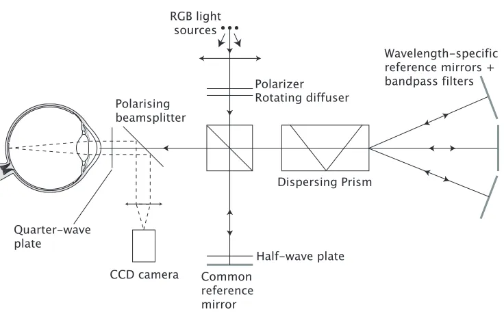
In the case of non-stationary targets such as in retinal imaging, we propose the simultaneous projection of fringes at three different wavelengths, as shown in Fig. 2. As each wavelength has its own mirror, the spatial frequency and phase of each fringe pattern can be adjusted separately to give sinusoidal patterns with the same spatial frequency and relative phases ofφ0,φ0+2π/3
andφ0−2π/3. It should be noted that the angleα affects the spatial frequency of the fringes
at the plane of the mirrors M1and M2. In practical cases, there will be a magnification which is
less than unity between this plane and the retinal plane. This magnification is a parameter that can be used to optimise the rate of change of spatial frequency of the illumination pattern with changing angleα.
4. Structured Illumination Ophthalmoscope
We can now describe an implementation of this novel methodology for obtaining structured illumination imaging applied to the field of retinal imaging. Achieving high lateral and axial resolution when imaging the living human retina is essential for early detection and diagnosis of retinal disease, when treatment is more effective and cost-efficient. Imaging devices that can resolve small retinal structures both laterally and in depth also aid clinicians who study these diseases and their treatment and management. The SLO was the first device to offer optical sectioning of the retina, and Optical Coherence Tomography (OCT) has the capability of achieving very high axial resolution. The Structured Illumination Ophthalmoscope (SIO) proposed in this Paper has a number of potential advantages over the existing systems. Unlike the SLO and OCT techniques, there is no lateral scanning as the illumination is wide-field. This makes the SIO an optically simple device that does not rely on mechanical scanning devices and the optical design trade-offs required for scanning systems. In addition to the potential for reduced design, engineering and production costs of future commercial devices, there is no distortion due to intra-frame eye movements and other potential artefacts introduced by the scanning processes in the SLO and OCT.
The use of incoherent light sources eliminates speckle effects that can introduce artefacts particularly when imaging at high resolution, and as none of the illumination light is discarded at the sample as with the confocal pinhole in the SLO, or the interference conditions required in OCT, the SIO is light efficient. In the SLO in particular, the trade-off between having a small confocal pinhole size which would give higher axial resolution, and having sufficient signal-to-noise ratio at the detector is a major drawback which the SIO does not suffer from. This latter point is especially important in retinal imaging since the incident light on the sample is limited by ocular safety considerations. The multispectral imaging characteristics of the SIO will also enable efficient imaging of more retinal layers and structures within a single image.
RGB light sources
Rotating diffuser Polarizer
Dispersing Prism
Half-wave plate Quarter-wave
plate
Common reference mirror
Wavelength-specific reference mirrors + bandpass filters
Polarising beamsplitter
[image:7.612.124.492.80.308.2]CCD camera
Fig. 2. Schematic representation of the proposed Structured Illumination Ophthalmoscope using the Fizeau fringe projection technique and three wavelengths for illumination. Red, green and blue incoherent light sources are used. These are matched to the detection peaks for the detectors in the colour CCD camera and, with appropriate filtering, cross-talk is minimised. A rotating diffuser is used to enhance spatial incoherence. A beamsplitter splits the light into the two branches of a Michelson interferometer, one containing a mirror common to all wavelengths, the other containing a dispersing prism and three mirrors, one for each of the illuminating wavelengths. The fringes produced are projected onto the retina by the optics of the eye. Incoming and outgoing light from the eye is split using a polarizing beamplitter and a quarter-wave plate in front of the eye to maximise the returning light based on the eye’s birefringence. A half-wave plate in the common branch of the interferometer controls fringe modulation.
to formalise the theory for the Fizeau fringe projection technique described.
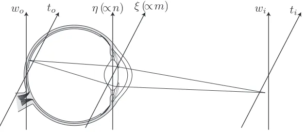
If we let (xo,yo)represent the lateral coordinates at the object plane (i.e. retina), we can then define the normalised coordinates(to,wo) =k(xo,yo)n sinα, where k=2π/λ and n sinα is the numerical aperture NA [6]. (Figure 3 shows a simplified schematic showing the relevant planes.) If the amplitude reflectance of the retina is r(to,wo)and it is illuminated by a structured incoherent intensity pattern given by
Iillumination(to,wo) =1+μcos(νto+φ), (1) whereμandν are the modulation and frequency respectively of the sinusoidal pattern, andφ is the phase, then the object intensity becomes
Iob ject(to,wo) = [1+μcos(νto+φ)]ρ(to,wo), (2) whereρ=|r|2is the intensity reflectance of the retina. The intensity image of this object formed incoherently at the image plane(ti,wi)is therefore
I(ti,wi) =
Fig. 3. Simplified geometry for the imaging system showing the object and image planes with their normalised coordinate pairs(to,wo)and(ti,wi)respectively, and the pupil plane
with coordinates(ξ,η)with are proportional to the spatial frequency coordinates(m,n)[6, 14]. Focussing optics is not shown.
where h is the amplitude point spread function of the objective (i.e. the optics of the eye). We assume unit magnification between object and image plane throughout these derivations, and integration is over all space. We can now expand Eq. 3 using the expansion of cosine in terms of Euler’s formula, and for compactness we pre-define the following functions:
I0(ti,wi) =
ρ(to,wo)|h(ti+to,wi+wo)|2dtodwo, (4)
Iν(ti,wi) =
eiνtoρ(t
o,wo)|h(ti+to,wi+wo)|2dtodwo, (5)
I−ν(ti,wi) =
e−iνtoρ(t
o,wo)|h(ti+to,wi+wo)|2dtodwo, (6) which yields
I(ti,wi) =I0(ti,wi) +μ 2 e
iφI
ν(ti,wi) +μ 2 e
−iφI
−ν(ti,wi). (7)
I0(ti,wi)is simply the conventional incoherent image in a standard microscope with homoge-nous illumination (μ=0), and we also note that I−ν=Iν∗, where∗denotes the complex conju-gate. The intensity image obtained using the structured illumination therefore can be considered as having three components, one of which is equivalent to the standard microscope. The relative weighting of these three components depends on the modulation of the illuminating pattern,μ. Before proceeding to show that Iν and I−ν possess axial sectioning properties, we note that in order to extract these components we require more than one intensity image so that I0can
be eliminated. Thus, three intensity images I1, I2 and I3 are obtained with phases φ1=φ0,
φ2=φ0+2π/3 andφ3=φ0−2π/3 respectively. We can therefore show that the desired
com-ponent can be obtained through either of the following two expressions [1, 3]:
|I±ν| = |I1+I2e∓i2π/3+I3e±i2π/3|, (8)
|I±ν| =
(I1−I2)2+ (I1−I3)2+ (I2−I3)2
2
1 2
. (9)
The conventional incoherent image can also be easily recovered from the three acquired images through
I0=
1
We can now define the object intensity spectrumR(m,n) =F{ρ(to,wo)}whereFrepresents the Fourier transform operator and(m,n)are spatial frequencies corresponding to(to,wo), we can therefore substitute forρin Eq. 5 to give
Iν(ti,wi) =
eiνtoR(m,n)e−i(mto+nwo)|h(t
i+to,wi+wo)|2dtodwodm dn. (11) Since P(m,n) =F−1{h(to,wo)}, where P is the generalised pupil function [6, 14], then through use of the shift theorem and autocorrelation theorem for Fourier transforms [15] we have
ei(mti+nwi)P(m,n)⊗P∗(m,n) = F−1{|h(t
o+ti,wo+wi)|2} (12)
=
|h(to+ti,wo+wi)|2e−i(mto+nwo)dtodwo. (13) In anticipation of our final result we define the transfer function C(m,n) =P(m,n)⊗P∗(m,n), and following a further application of the shift theorem to take into account the exponential term in Eq. 11 we get
Iν(ti,wi) =eiνti
R(m,n)C(m+ν,n)ei(mti+nwi)dm dn. (14)
In order to investigate the effect of defocus on the structured illumination microscope, we need to consider the effect of defocus on the illumination pattern. This is fairly straightforward for the grid projection and fringe projection techniques. In the former, as the illumination pat-tern is an image of a sinusoidal grid formed on the sample, the axial behaviour of the structured pattern is determined by the three-dimensional point spread function of the collector lens which is responsible for the illumination. The modulation of the sinusoidal pattern therefore decreases with defocus. In fringe illumination the sinusoidal pattern is formed through the interference of two laser beams and is independent of axial position; the modulation therefore does not decrease with defocus. For the Fizeau fringe projection technique described in this Paper, the defocus considerations are more involved as described above. One practical scenario is the case when the extended source is small or distant so that we can assume all rays are nearly parallel to the optical axis. This is a valid assumption for an ophthalmic imaging system owing to the restrictions imposed by the pupil of the eye. In this case we can assume that the modulationμ of the sinusoidal pattern is not a function of defocus. Equation 3 can therefore be rewritten as
I(ti,wi; u) =
[1+μcos(νto+φ)]ρ(to,wo; u)|h(ti+to,wi+wo; u)|2dtodwo, (15) where u is the normalised axial coordinate representing defocus, related to the actual axial coordinate z through u=4knz sin2(α/2). Similarly, all subsequent equations derived from Eq. 3 become functions of u.
the optical sectioning properties of the imaging system. On the other hand, the use of different wavelengths to obtain the three required intensity images, while making the technique feasible for ophthalmic use, will affect the axial sectioning capabilities as the I0term will not be fully
eliminated in Eqs. 8 and 9. Future work to be published later includes detailed simulation of these processes to investigate and quantify their effects on resolution.
5. Conclusion
A novel implementation of structured illumination microscopy has been described and assessed theoretically in this Paper. The technique is suited for the imaging of non-stationary objects, in-cluding in-vivo retinal imaging. The novel aspects of the technique proposed include a new technique to deliver the sinusoidal illumination pattern required for structured illumination, namely a Fizeau (incoherent) fringe projection technique, and a multiple wavelength illumi-nation system that enables the three images required with phase-shifted structured patterns to be acquired simultaneously, rather than sequentially, enabling imaging of moving objects. We show that for practical implementations in the ophthalmic case, the theoretical axial sectioning is identical to that obtained through fluorescence imaging through structured illumination with the coherent fringe projection system, and in the general case the geometry of the extended source in relation to the objective can be altered to improve the axial sectioning further.
In the application to retinal imaging, this technique has the potential to obtain axially sec-tioned images comparable to those of the SLO. It also offers a number of advantages over the SLO which include better light efficiency, improved lateral resolution, multi-spectral imag-ing and a marked reduction in optical and opto-mechanical complexity as no lateral scannimag-ing mechanisms are required. The latter point has implications in image quality but also in poten-tial future development and manufacture costs, and maintenance and reliability of commercial devices. The potential for an inexpensive retinal imaging system with high quality 3D imaging capabilities is one of importance clinically in the drive to detect retinal disease early through screening.
Acknowledgments