This is a peer-reviewed accepted author manuscript. Due for official publication during 2015 in Tribology International (ISSN: 0301-679X). Tribo-Oxidation maps for Ti against steel
G. Rasool and M.M. Stack*
Department of Mechanical and Aerospace Engineering
University of Strathclyde,
James Weir Building, 75 Montrose St.,
Glasgow, G1 1XJ
*Corresponding author e-mail: [email protected]; Tel 44 141 5483754; Fax 44 141
5525105
Abstract
A fundamental study of wear transition regimes was carried out for a pin-on-disk sliding couple, involving titanium and steel. The sliding speed was varied from 0.38 to 1.5m s-1 and the normal load from 10 to 50N. Wear mapping approaches have been undertaken to represent the transitions in wear modes and wear mechanisms regimes, as a function of applied normal loads and sliding speeds and for both pin and disc separately on the basis of experimental results. Dry sliding wear behaviour of Steel was characterized by tribo-oxidative wear with high material transfer from the titanium. In contrast, adhesive wear was more prevalent for the titanium and oxidative wear mechanisms led to formation of non-protective films on the surface.
Keywords: pin-on-disk, sliding speed, normal load, wear rate, tribo-corrosion maps 1. Introduction
The applications of titanium and its alloys are of significant interest due to their favourable properties such as high strength, low density and high corrosion resistance especially in room temperature and for applications involving biological environments [1- 2]. Due to low hardness and wear resistance, however, they have several limitations [2]. Pure titanium is known for relatively challenging tribological properties [3-4]. This factor may limit its application particularly in areas involving wear and friction [5]. Two main factors have been suggested as responsible for such observations [4], namely low resistance to plastic shearing and low work hardening, and poor protection exerted by the surface oxide which may form as a consequence of the high flash temperature induced by frictional heating.
Despite the above observations, systematic studies which analyse wear mechanisms of titanium over a wide range of parameters are not available. Studies in the literature on the wear behaviour of titanium against hardened metal in dry sliding contacts indicated severe wear of titanium, and following analysis of metallic wear debris, suggested plastic deformation and flow and transfer of the softer material [1]. Moreover, the transfer of the soft material to its hard counterpart in dry sliding conditions was observed for several cases [6-9]. Cocks and Antler found transfer of material following the wear of metal from the latter [10-11]. It was found that the tribological behaviour of this couple was consistent with that of such materials found in literature.
2.Experimental conditions
Dry sliding wear tests were carried out in ambient conditions on a pin-on-disk wear testing rig. The normally loaded stationary titanium pins of 4.3mm diameter, with flat ends were slid against rotating hardened gauge plate disks 3.8mm in thickness and 75mm outer diameter. The tests were carried out at different constant sliding speeds, 0.38, 0.5, 0.86, 1.2 and 1.5m s-1 by varying normal loads in increments of 10 N, from 10 to 50N for all combinations of sliding speeds and normal loads. The sliding distance was 5,560m and the numbers of revolutions were 30,000 for each combination of sliding speed and normal load. A different disk and pin pair were used for each test. An analytical balance with accuracy of 0.01 mg was used to evaluate mass loss following exposure. The wear rates (m3 m-1) were calculated by converting mass loss to volume loss from the densities of both materials and then dividing the volume loss by the sliding distance. SEM micrograph and EDX analysis of the worn surfaces and wear debris were carried out to study the wear modes and wear mechanisms of these materials against each other.
2.1.Materials
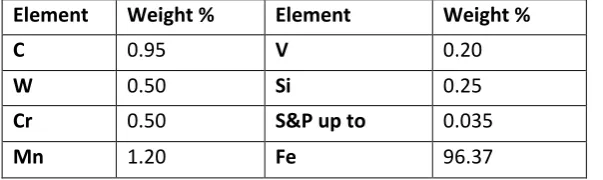
[image:2.595.145.447.367.457.2]2.1.1. The chemical composition of the steel gauge plate (A.I.S.I. 0-1-Ground Flat Stock) disk, provided by the steel supplie,is shown on Table 1.
Table 1.The chemical composition of the gauge plate (A.I.S.I. 0-1-Ground Flat Stock) disk
Element Weight % Element Weight %
C 0.95 V 0.20
W 0.50 Si 0.25
Cr 0.50 S&P up to 0.035
Mn 1.20 Fe 96.37
2.2. The hardness values of titanium: 184HV5 and of hardened gauge plate steel (A.I.S.I. 0-1-Ground Flat Stock): 701HV5. The density of titanium and the steel were 4.51g cm-3 and 7.8g cm-3
respectively, were used for wear rates calculation. 3.Wear tests results
3.1. Wear rate comparison of titanium pins and steel
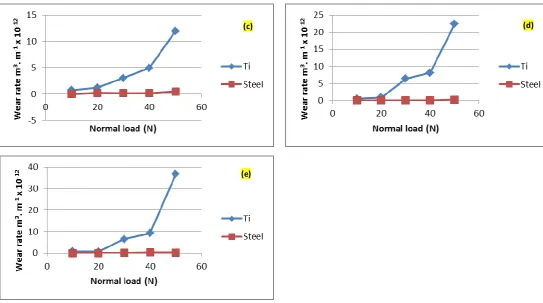
Fig. 1 shows the wear rate comparison of titanium pins against steel. The wear resistance of titanium pins was lower when sliding against the steel pins, as normal load increased. Negative wear rate of disk at sliding speed 0.86 m s-1 and normal load 10 N resulted from the transfer of pin material to disk Fig. 1(c).
[image:2.595.19.574.645.791.2]
Fig. 1 Wear rate comparison of titanium and steel (a) at sliding speed 0.38m s-1 and various normal load, (b) at 0.5m s-1 and various normal load, (c) at 0.86m s-1 and various normal load, (d) at 1.2m s-1 and various normal load, and (e) at 1.5m s-1 and various normal load.
3.2. Wear rate of titanium pins against hardened gauge plate disks
Fig. 2(a) shows the wear rate of titanium pins against hardened gauge plate disks at constant sliding speeds and variable normal loads and Fig. 2(b) shows the wear rate of titanium pins against
hardened gauge plate disks at constant normal loads and variable sliding speeds.
Fig. 2 (a) Wear rate vs normal loads of ti pins against hardened gauge plate disks and (b) wear rate vs sliding speeds of Ti pins against hardened gauge plate disk
3.3. Wear rate of hardened gauge plate disks against titanium pins
Fig. 3(a) shows the wear rate of hardened gauge plate disks against titanium pins at constant sliding speeds and variable normal loads and Fig. 3(b) shows the wear rate of hardened gauge plate disks against titanium pins at constant normal loads and variable sliding speeds.
(
a
)
(
b
)
(
c) (d)
[image:3.595.12.583.512.661.2]
Fig. 3 (a) Wear rate vs normal load of hardened gauge plate disks against ti pins and (b) wear rate vs sliding speed of hardened gauge plate disks against Ti pins
Fig. 2 shows that wear rate of Ti pins increases with the increase in normal loads and sliding speeds. There was a significant increase in wear rate at higher normal load for the range of sliding speeds Fig. 2(a). Moreover, for the each normal load there is minimum wear rate at an intermediate sliding speed
i.e. 0.5m s-1 Fig. 2(b). The wear rate of the steel was higher at lower sliding speeds and decreased with increase in sliding speeds and normal loads Fig. 3.
[image:4.595.18.589.65.211.2]3.4. Total mass loss comparison
Fig. 4 shows the total mass loss of the titanium pins and hardened gauge plate disks at each constant sliding speed for the range of normal loads i.e. at variable loads from 10 to 50 N for the total sliding distance 27,800m. The total mass loss of the titanium pins is much higher than that of hardened gauge plate. Moreover, the total wear of titanium increased rapidly, while the total mass loss of the hardened steel decreased with increase in sliding speeds.
Fig. 4 The total mass loss comparison of steel disk and titanium pin
3.5. SEM micrographs and EDX analysis of the worn surfaces
Fig. 5 shows the SEM micrographs of the worn surfaces of the titanium pins and hardened steel plate disks.
0
0.5
1
( a
1.5
)
0.38
( b
0.5
)
0.86 1.2 1.5
Mass loss (g)
Sliding speed ( m s -1)
Ti
[image:4.595.107.477.469.627.2]
Fig. 5 SEM micrographs of the worn surfaces of pins and wear tracks of the disks, (a) at normal load 20N and sliding speed 0.38m s-1, (b) at 40N and 0.38m s-1, (c) at 30N and 0.5m s-1, (d) at 40 and 0.86m s-1, (e) at 50N and 0.86m s-1, (f) at 10N and 1.2m s-1 and (g) at 50N and 1.2m s-1.
b
( pin) ( b disk)
( c pin) ( c disk)
( d disk) ( d pin)
( e disk) e
( pin)
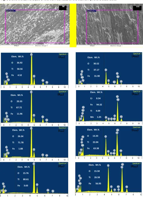
Fig. 6 shows the EDX analysis of the worn surfaces of the titanium pins and steel disks.
( g disk) ( g pin)
( a disk)
Elem. Wt.%
O 30.52
Ti 37.17
Fe 31.90
b ( disk)
Elem. Wt.%
Cr 0.54
Fe 94.32
Ti 4.09
Mn 1.05
( a pin)
Elem. Wt.%
O 36.92
Ti 58.56
Fe 4.52
( b pin)
Elem. Wt.%
O 20.33
Ti 67.72
Fe 11.96
c ( disk)
Elem. Wt.%
O 13.33
Ti 22.04
Fe 63.38
( c pin)
Elem. Wt.%
O 26.34
Ti 71.78
Fe 1.88
d ( disk)
Elem. Wt.%
O 15.50
Ti 26.58
Fe 56.93
( d pin)
Elem. Wt.%
O 15.76
Ti 80.61
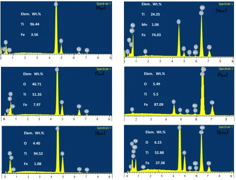
Fig. 6. EDX analysis of the worn surfaces of pins and wear track of the disks, , (a) at normal load 20N and sliding speed 0.38m s-1, (b) at 40N and 0.38m s-1, (c) at 30N and 0.5m s-1, (d) at 40 and 0.86m s-1, (e) at 50N and 0.86m s-1, (f) at 10N and 1.2m s-1 and (g) at 50N and 1.2m s-1.
Material transfer between specimen and counterpace occurred during this sliding system Fig. 6. At lower sliding speed, less pins material transferred to disk. At higher sliding speeds and normal loads, the pins material transfer was significant Fig. 1 & 2. The SEM micrographs show that the wear of the Ti pins occurred by various wear mechanisms i.e. adhesive, oxidational, plastic deformation,
delamination and abrasive wear mechanisms Fig. 5.
For the steel disks at lower sliding speeds, material transfer was evident. SEM micrographs indicates adhesion on wear track Fig. 5 and there was no trace of oxide on the worn surface Fig. 6. Evidence of disk material was also found on the pins‟ worn surfaces Fig. 6. Moreover, traces of titanium, iron and oxygen on the worn surfaces of the Ti pins and disks indicate that wear processes involved oxidative processes, Figs. 6.
3.6. SEM and EDX analysis of the wear debris Fig. 7 shows the SEM micrograph of the wear debris
( e disk)
Elem. Wt.%
Ti 24.25
Mn 1.06
Fe 74.03
( e pin)
Elem. Wt.%
Ti 96.44
Fe 3.56
f ( disk)
Elem. Wt.%
O 5.49
Ti 5.5
Fe 87.09
g ( disk)
Elem. Wt.%
O 6.15
Ti 52.88
Fe 37.38
g ( pin)
Elem. Wt.%
O 4.40
Ti 94.52
Fe 1.08
( f pin)
Elem Wt.%
O 40.71
Ti 51.35
[image:9.595.278.528.576.825.2]
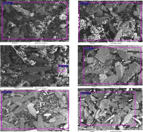
Fig. 7 SEM micrograph of wear debris of titanium against steel (a) at sliding speed 0.38m s-1 and normal load 20N, (b) at 0.38m s-1 and 50N, (c) at 0.5m s-1 and 50N, (d) at 0.86m s-1 and 30N, and (e) at 1.2m s-1 and 50N, and (f) at 1.5m s-1 and 30N.
Fig. 8 shows the EDX analysis of the wear debris ( b )
Elem Wt.%
O 15.57
Ti 65.72
Fe 18.28
( )
Al 0.19
a
Mn 0.24
( )
Elem Wt.%
b
O 26.86
) c
Ti 63.10
(
Fe 9.46
( d
Al 0.41
)
Si
(
0.18
f )
) a ) ( ( e
Elem Wt.%
O 23.96
Ti 63.70
Fe 12.34
( c ) Elem Wt.%
O 23.69
Ti 71.25
Fe 4.79
Ni 0.27
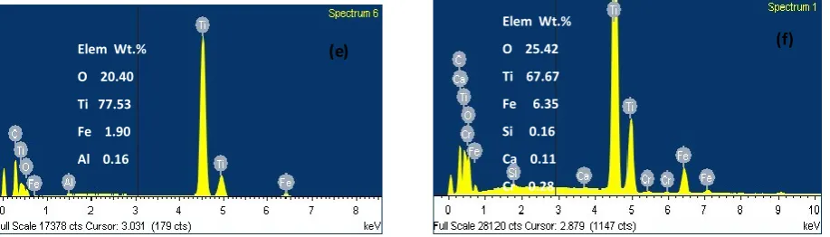
Fig. 8 EDX analysis of wear debris Titanium against Steel (a) at sliding speed 0.38m s-1 and normal load 20N, (b) at 0.38m s-1 and 50N, (c) at 0.5m s-1 and 50N, (d) at 0.86m s-1 and 30N, and (e) at 1.2m s-1 and 50N, and (f) at 1.5m s-1 and 30N.
SEM micrographs of the wear debris indicate various types and sizes of wear debris observed for the range of sliding speed and normal loads Fig. 7. The shapes of debris vary and of a different
configuration as sliding speeds was increased, Fig. 7(a-f). At lower sliding speeds, wear products consisted of fine compact particles, metallic debris, along with fine grey oxide power, Fig. 7(a-c) while at higher sliding speeds larger flake-like metallic particles and fine grey powers of titanium oxide Fig. 7(d-f) were observed.The composition of wear debris mainly consisted of titanium, oxygen and iron. The higher proportions of titanium and oxygen indicate that oxidation of titanium
occurred during sliding for all combinations of sliding speed and normal loads Fig. 8. 4.Discussion
From Figs. 1 & 2, higher wear rates of titanium pins against steel are attributed to its lower hardness, low work hardening and inability to form protective oxide layer [4]. With the increase in normal load, a significant increase in wear rate of the titanium pins for the range of sliding speeds suggests severe sliding conditions, accompanied by plastic deformation and flow of the softer material Fig. 2(a), [1]. Similar results are found for titanium and its alloys against hard metals in the work of other authors [5 & 21]. These observations are also consistent with previous work [31] where 303SS shows similar wear behaviour against alumina and in other work found in literature [37]. With the increase in sliding speed, a progressive increase in wear is induced due to thermal softening associated with the reduction in the yield point of the material. The effects of an increase in sliding speed results in an increase in delamination wear [4, 22]. Fig. 2(b) shows the lower wear rate of titanium at 0.5m s-1 for the range of normal loads, resulted from the higher oxidation rates at this speed Figs. 5(c) & 6(c), [4]. Oxidative wear can lead to lower wear rates, as is shown in other work [22]. As the normal load increases, tribo-oxidation is accompanied by plastic deformation [23]. During continuous sliding, the initial transferred fragments are deformed, fractured and blended, leading to formation of a “mechanically mixed material” on the wear track. The hardness of the mixed material formed is considerably higher than that of the soft pin material due to the intense, localised, thermal effects which occur during rubbing under unlubricated conditions. Typically, sliding wear debris particles comprise a modified mixed layer [24] and are generated from the adhered titanium particles detached from the sliding track, together with a thin film of counterpart material. EDX analysis Fig. 8 confirms that during dry sliding, frictional heat generation results in high temperatures at the contact area leading to oxidation of titanium for all combinations of sliding speeds and normal loads.
The sliding of metals can be described by the following basic wear sequence: surface and sub-surface plastic deformation, formation of debris and material transfer, reaction with the environment, and
f ( )
Elem Wt.%
O 25.42
Ti 67.67
Fe 6.35
Si 0.16
Ca 0.11
Cr 0.28 Elem Wt.%
O 20.40
Ti 77.53
Fe 1.90
Al 0.16
mechanical mixing leading to the production of a tribological layer [12]. Material transfer is related to the junction adhesion. The amount of material transferred varies for each combination of sliding and normal load. [6].
4.1. Wear maps
Wear maps can represent the mechanistic changes on the worn surfaces of material and the counterpart over a range of operating conditions [33]. Wear mode maps identify the mode of degradation and establish the level of wastage rate and potential „„safe‟ ‟ and “unsafe” operation conditions for materials [34]. Wear mechanistic maps show the different wear mechanisms for different materials in tribological contact, on the basis of experimental observations [5, 35]. Such maps link the observed wear mechanisms to the actual conditions. These maps demonstrate clearly that transitions from one dominant wear mechanism to another may also be identified by changes in measured wear rates [33].
4.1.1. Wear mode regimes and maps
Fig. 9 shows the wear modes maps for both specimens and counterparts. The classifications of wear mode into three distinct regimes, namely (a) mild wear, (b) medium wear and (d) severe wear, have been made on the basis experimental observations and analysis of worn surfaces and wear products. The wear modes and regimes are consistent with the previous studies by the present authors [30, 37] and research work found in the literature [26-29, 31-32].The wear modes regimes limits are as below:a)Mild wear ≤ *1.12 x 10⁻¹²(m3 m-1 )]
b) [1.12 x 10⁻¹² (m3 m-1)] ˂ medium wear ≤ *3.35 x 10⁻¹²(m3 m-1)] c) Severe wear ˂ [3.35 x 10⁻¹² (m3 m-1)]
4.2.1. Wear mode maps
[image:11.595.76.512.487.656.2]
Fig. 9 Wear mode map (a) Titanium pins against Steel disks and (b) Steel disks against Ti pins.
In these maps various wear mode regimes and wear mode transitions are identified for the Titanium pins Fig. 9(a) and Steel, Fig. 9(b), as a function of sliding speeds and normal loads. It can be clearly seen that severe wear is more prevalent with respective to normal load for Titanium pins whereas mild wear is more prevalent for the Steel. Moreover in Figs. 9(a-b), the combination of the mild wear zone can be regarded as the safe operation zone for the titanium and steel for the range of sliding speeds and normal loads.
4.1.2. Wear mechanisms regimes and maps
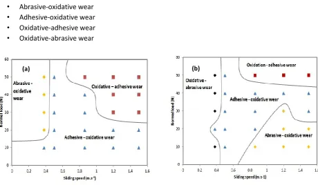
Fig. 10 shows the wear mechanisms maps for Ti and steel for the range of sliding speeds and normal loads. The wear regimes below are based on the experimental observations and can be summarized as:
• Abrasive-oxidative wear • Adhesive-oxidative wear • Oxidative-adhesive wear • Oxidative-abrasive wear
Fig. 10 Wear mechanism maps (a) Ti pins against steel disks and (b) steel disks against Ti pins.
From Fig, 10(a), in the „„adhesive-oxidative wear‟ ‟ regime, wear fragments were generated due to adhesion between mating sliding surfaces. This mechanically mixed layer comprises oxidative- wear products, Figs. 5(c - d) and 6(c - d) respectively, with the presence of oxide particles clearly in evidence. Analysis of wear debris shows fine compact grey oxide powder and particles (identified as metallic titanium) Figs. 7(c-d) - 8(c-d) [1]. With the increase in sliding speed, frictional heat leads to further oxidation of the surfaces in contact [4, 18-20]. In this regime, with the high contact temperatures, there is was more evidence of adhesion than abrasion. For the „„oxidative-adhesive wear‟ ‟ regime, Fig. 10(a), severe adhesive wear and plastic deformation led to the higher wear rate of the titanium pins in this region, Figs. 5(e, g) and 6(e, g), due to high contact temperatures. The flake like shape of metallic wear debris Figs. 7(e-f) and the presence of higher proportions of titanium and oxygen in the wear products, Figs. 8(e-f) indicate that oxidative wear was followed by adhesive wear. In such severe sliding conditions, material transfer, wear, and surface degradation rates are higher. Metallic wear debris is produced rapidly and the particles generated from the wear process are larger in size [25]. Similar wear mechanisms are suggested by Straffelini and Molinari [4] and Ohidul Alam and Haseeb [5] for Ti-6Al-4V alloy against hardened steel.
For the „„abrasive-oxidative wear‟ ‟ regime, Fig. 10, oxide scale together with metallic Ti and Fe acts as an abradent on the surfaces, Fig. 5(a, f) and 6(a, f). Adhesion is less evident due to the lower contact temperatures. The nature and shape of the wear deris for this and the above regimes, Fig. 7(a-b) and 8(a-7(a-b), identify the major difference between the interaction of oxidation with the abrasive and adhesive wear mechanisms.
4.3. Wear mechanisms comparison between Ti sliding against hardened gauge plate counterface and 303SS sliding against alumina counterface
[image:13.595.77.347.122.317.2]
Fig. 11 The wear mechanistic maps for 303SS against alumina
Fig. 11 shows the wear mechanistic maps for 303SS against alumina taken from our previous work [30] and can be compared with the wear mechanisms of our present work Fig. 10(a). It is clear through comparing (although against different counterface materials) that the oxidative wear mechanism is more prevalent for titanium against the steel counterface.
Clearly, the wear maps developed above indicate many possible wear regime transitions between titanium and steel. Further work will be to investigate the wear mechanisms of Ti base TiC composite coatings against hardened steel to provide a basis for coating optimization in such conditions.
5.Conclusions
1. For titanium sliding against steel, oxidative wear dominates at lower loads for the range of sliding speeds tested and is associated with relatively high wear rates indicating the non-protective nature of the oxide formed.
2. The titanium/steel sliding couple results in severe sliding conditions with adhesive wear, delamination, plastic deformation and material flow wear and abrasive wear of the pin metal. 3. A mechanically mixed metal layer develops under various combinations of sliding speed and normal load. However, the protective role of this layer depends on the oxide morphology and the contact conditions.
Acknowledgements
We would like to extend our thanks to IIUM, Malaysia for providing test specimens for the present work and in particular Dr. Shahjahan Mridha, Leverhulme Trust Visiting Professor –grant no.
References
[1] S. Krol, L. Ptacek, M. Hepner, Friction and wear properties of titanium and oxidised titanium in dry sliding against hardened C45 steel, Journal of Materials Processing Technology, 157-158 (2004) 364-369.
[2] A. Monfared, A. H. Kokabi, S. Asgari, Microstructural studies and wear assessments of Ti/TiC surface composite coatings on commercial pure Ti produced by titanium cored wires and TIG process, Materials Chemistry and Physics,137 (2013), Pages 959-966.
[3] K. G. Budinski, Tribologycal properties of titanium alloys, Wear, 151 (1991), Pages 203-217.
[4] A. Molinari, G. Straffelini, B. Tesi, T. Bacci, Dry sliding wear mechanisms of Ti6Al4V alloy, Wear, 208 (1997), Pages 105-112.
[5] Md. OhidulAlam, A. S. M. A. Haseeb, Response of Ti-6Al-4V and Ti-24Al-11Nb alloys to dry sliding wear against hardened steel, Tribology International, 35 (2002), Pages 357-362. [6] M. Kerridge, Metal transfer and the wear process, Proc. R. Soc. London, Sect. B(2ndedn.), Pages 400-407.
[7] M. Kerridge and J. K. Lancaster, The stages in a process of severe metallic wear, Proc. Roy. Soc. (London), A236 (1956), Pages 250-264.
[8] A. W. J. De Gee and J. H. Zaat, Wear of copper alloys against steel in oxygen and argon, Wear, 5 (1962), Pages 257-274.
[9] R. H. Brown and E. J. A. Armarego, Some observations on the friction and wear of a hardened rider, Wear, 6 (1963), Pages 106-117.
[10] M. Cocks, Interaction of sliding metal surfaces, J. Appl. Phys., 33 (1962), Pages 2152-2161. [11] M. Antler, Wear, friction, and electrical noise phenomena in severe sliding systems, ASLE Trans., 5 (1962), Pages 257-274.
[12] D. A. Rigney, Some thoughts on sliding wear, Wear, 152 (1992), Pages 187-192.
[13] J. F. Archard and W. Hirst, The wear of metals under unlubricated conditions, Proc. R. Soc., Lond. A, 236 (1956), Pages 397-410.
[14] J. K. Lancaster, The formation of surface films at the transition between mild and severe metallic wear, Proc. R. Soc., Lond. A, 273 (1963), Pages 466-483.
[16] T.S. Eyre, D. Maynard, Surface aspects of unlubricated metal-metal wear, Wear, 18 (1971), Pages 301-310.
[17] F. H. Stott, J. Glascott and G. C. Wood, The sliding wear of commercial Fe-12SgoCr alloys at high temperature, Wear, 101 (1985), Pages 311-324.
[18] NagarajChelliah, Satish V. Kailas, Synergy between tribo-oxidation and strain rate response on governing the dry sliding wear behaviour of titanium, Wear 266 (2009), Pages 704-712.
[19] M. M. Stack, J. Jiang, F.H. Stott, A generic model for dry sliding wear of metals at elevated temperatures, Wear, Vol. 256, Issues 9-10, May 2004, Pages 973-985.
[20] M. M. Stack, J. Jiang, F.H. Stott, Some frictional features associated with sliding wear of the nickle-base alloy N80A at temperature to 250oC,Wear 176 (1994), Pages 185-194.
[21] Y. S. Mao, L. Wang, K. M. Chen, S. Q. Wang and X. H. Cui, Tribo-layer and its role in dry sliding wear of Ti-6Al-4V alloy, Wear, 297, Issue 1-2 (2013), Pages 1032-1039.
[22] S. C. Lim, M.F. Ashby, Overview no. 55 wear-mechanism maps, ActaMetallurgica, 35(1987), Pages 1-24.
[23] I.I. Garbar, Gradation of oxidational wear of metals, Triboloy International, 35 (2002), Pages 749-775.
[24] D. A. Rigney, L. H. Chen, M. G. S. Naylor and A. R. Rosedfield, Wear process in sliding systems, Wear, 100 (1984), Pages 195-219.
[25] M. Antler, Processes of metal transfer and wear, Wear, 7 (1964), Pages 181-203.
[26] J.F. Archard, W. Hirst, The wear of metals under unlubricated conditions, Proc. Roy. Soc. London. A 236 (1956), Pages 397-410.
[27] J.F. Archard, W. Hirst, An examination of a mild wear process, Proc. Roy. Soc. London, A 238 (1957), Pages 515-528.
[28] J.T. Burwell, C.D. Strang, on the empirical law of adhesive wear, J. Appl. Phys., 23(1952), Pages 18-28.
[29] C.C. Viafara, M.I. Castro, J.M. Velez, A. Toro, Unlubricated sliding wear of pearlitic and
[30] G. Rasool and M. M. Stack, Wear maps for TiC composite based coatings deposited on 303 stainless steel, Tribology International, 74 (2014), Pages 93-102.
[32] J. Zhang and A. T. Alpas, Transition between mild and severe wear in aluminium alloys, Acta mater., Vol. 45, No. 2,(1997), Pages 513-528.
[33] C. Y. H. Lim, S. C. Lim, K. S. Lee, Wear of TiC-coated carbide tools in dry turning, Wear, 225-229 (1999), Pages 354-367.
[34] M. M. Stack, W. Huang, G. Wang, C. Hodge, Some views on the construction of bio-tribo- corrosion maps for Titanium alloys in Hank‟s solution: Particle concentration and applied loads effects, Tribology International, 44 ( 2011), Pages1827-1837.
[35] H. Kato, T. S. Eyre and B. Ralph, Wear mechanism map of nitride steel, Acta Metall. Mater. 42
(1994), Pages 1703-1713.
[36] K. H. ZUM GAHR, Sliding wear of ceramic- ceramic, ceramic-steel and steel-steel pairs in lubricated and unlubricated contact Wear, 133 (1989), Pages 1-22.
[37] G. Rasool and M.M. Stack, Mapping the role of Cr content in dry sliding of steels: comparison between maps for material and counterface, Tribology International, Volume 80, December 2014, Pages 49-57
List of Table
Table 1:The chemical composition of the gauge plate (A.I.S.I. 0-1-Ground Flat Stock) disk
List of Figure
Fig.1. Wear rate comparison of Ti and hardened gauge plate, (a) at 0.38ms-1 sliding speed and various normal load, (b) at 0.5ms-1 sliding speed and various normal load, (c) at 0.86ms-1 sliding speed and various normal load, (d) at 1.2ms-1 sliding speed and various normal load, and (e) at 1.5ms-1 sliding speed and various normal load.
Fig.2. (a) Wear rate vs normal load of Ti pin against hardened gauge plate disk and (b) wear rate vs sliding speed of Ti pin against hardened gauge plate disk
Fig.3. (a) Wear rate vs normal load of hardened gauge plate disk against Ti pin and (b) wear rate vs sliding speed of hardened gauge plate disk against Ti pin
Fig. 4. The total mass loss comparison of hardened gauge plate disk and Ti pin.
Fig. 6. EDX analysis of the worn surfaces, (a) at 20N normal load and 0.38m.s-1 sliding speed, (b) at 40N normal load and 0.38m.s-1 sliding speed, (c) at 30N normal load and 0.5m.s-1 sliding speed, (d) at 40Nnormal load and 0.86m.s-1 sliding speed, (e) at 50N normal load and 0.86m.s-1 sliding speed, (f) at 10N normal load and 1.2m.s-1 sliding speed, (g) at 50N normal load and 1.2m.s-1 sliding speed.
Fig. 7. SEM micrograph of wear debris of Ti against hardened gauge plate (a) at 0.38m s-1 sliding speed and 20N normal load, (b) at 0.38m s-1 sliding speed and 50N normal load, (c) at 0.5m s-1 sliding speed and 50N normal load, (d) at 0.86m s-1 sliding speed and 30N normal load, and (e) at 1.2m s-1 sliding speed and 50N normal, and (f) at 1.5m s-1 sliding speed and 30N normal load.
Fig. 8. EDX analysis of wear debris of Ti against hardened gauge plate(a) at 0.38m s-1 sliding speed and 20N normal load, (b) at 0.38m s-1 sliding speed and 50N normal load, (c) at 0.5m s-1 sliding speed and 50N normal load, (d) at 0.86m s-1 sliding speed and 30N normal load, and (e) at 1.2m s-1 sliding speed and 50N normal, and (f) at 1.5m s-1 sliding speed and 30N normal load.
Fig. 9. Wear mode map (a) Ti pin against hardened gauge plate disk and (b) hardened gauge plate
disk against Ti pin.
Fig. 10. Wear mechanism map (a) Ti pin against hardened gauge plate disk and (b) hardened gauge
plate disk against Ti pin.