City, University of London Institutional Repository
Citation
:
Soltanian, M. R. K., Sharbirin, A. S., Ariannejad, M. M., Amiri, I. S., De La Rue,
R. M., Brambilla, G., Rahman, B. M., Grattan, K. T. V. & Ahmad, H. (2016). Variable
Waist-Diameter Mach-Zehnder Tapered-Fiber Interferometer as Humidity and Temperature Sensor.
IEEE Sensors Journal, 16(15), pp. 5987-5992. doi: 10.1109/JSEN.2016.2573961
This is the accepted version of the paper.
This version of the publication may differ from the final published
version.
Permanent repository link:
http://openaccess.city.ac.uk/15118/
Link to published version
:
http://dx.doi.org/10.1109/JSEN.2016.2573961
Copyright and reuse:
City Research Online aims to make research
outputs of City, University of London available to a wider audience.
Copyright and Moral Rights remain with the author(s) and/or copyright
holders. URLs from City Research Online may be freely distributed and
linked to.
City Research Online:
http://openaccess.city.ac.uk/
[email protected]
Variable Waist-Diameter Mach–Zehnder
Tapered-Fiber Interferometer as Humidity
and Temperature Sensor
M. R. K. Soltanian, A. S. Sharbirin, M. M. Ariannejad, I. S. Amiri, R. M. De La Rue, Fellow, IEEE,
G. Brambilla, B. M. A. Rahman, K. T. V. Grattan, and H. Ahmad
Abstract— In-line single-mode tapered-fiber Mach–Zehnder
interferometer (MZI-SMTF) with average waist diameters (davg)
of 4.05 and 2.89 µm have been fabricated, and both the temperature and the humidity sensitivity of the surround-ing media have been measured and compared. The humidity and the temperature were measured over the ranges from 0% to 90% and 28 °C to 40 °C, respectively. The stability of the system at 50%RH and 90%RH was investigated, while the temperature of the chamber was maintained at about 28 °C. The humidity and temperature sensitivity resolution values were 0.02 nm/%RH and 0.05 nm/0.1 °C for the MZI-SMTF-1 with an average waist diameter of 4.05 µm, while they were 0.01 nm/%RH and 0.025 nm/0.1 °C for the MZI-SMTF-2 with an average waist diameter of 2.89µm.
Index Terms— Fiber sensor, inline MZI, tapered fiber, humidity
sensor, temperature sensor.
I. INTRODUCTION
H
UMIDITY and temperature monitoring are vital in various industrial applications, e.g. the production of chemical substances, mining activities and inbiomedical plants since it enables control of product quality and protection of workers’ health. Additionally it is important in the avoidance and control of corrosion in large structures - for example aircraft and bridges [1]. Subsequently, there has been extensive analysis on relative humidity (RH) and temperature sensors in various approaches including capacitive, resistive and optical humidity and temperature sensors. The humidity and tem-perature sensor market has been monopolized by electronicM. R. K. Soltanian, A. S. Sharbirin, M. M. Ariannejad, I. S. Amiri, and H. Ahmad are with the Photonics Research Center, University of Malaya, Kuala Lumpur 50603, Malaysia (e-mail: [email protected]; [email protected]; [email protected]; [email protected]; [email protected]).
R. M. De La Rue is with the Department of Electronics and Electri-cal Engineering, University of Glasgow, Glasgow G12 8LT, U.K. (e-mail: [email protected]).
G. Brambilla is with the Optoelectronics Research Center, University of Southampton, Southampton SO17 1BJ, U.K. (e-mail: [email protected]).
B. M. A. Rahman and K. T. V. Grattan are with the School of Mathe-matics, Computer Science and Engineering, City University London, London EC1V 0HB, U.K. (e-mail: [email protected]; [email protected]).
digital sensors. Nevertheless, due to advances in the field of fiber optical sensing, niche applications can be found where fiber optical humidity and temperature sensors can strongly compete with their electronics humidity and temperature counterparts.
Transmit a huge amount of data taken from optical sen-sors over a long distance, due to large bandwidth and low attenuation of optical fiber give their market a huge priority. On top of that, the application of several approaches to interro-gation enable the applications to design distributed humidity and temperature sensor [2]. In addition, the electromagnetic interference is one the main issue for the electrical humidity and temperature sensors and it prevents utilization of this kind of sensors. Moreover, the small dimensions of the optical fiber sensors make them suitable to packaging into lightweight devices or embedded in polymer materials ergonomically. Last but not least, the sensitivity of optical fiber sensors are normally higher than the conventional sensors once they operate at high resolution [3], [4]. The guided light in the fiber core and the surrounding medium (evanescent field effect for tapered fiber) collected in fiber optic humidity sensors (FOHS). Meanwhile the ambient temperature and humidity changes the surrounding medium’s refractive index. Consequently, it affects the transmission and reflection of the guided light that interacts with the surrounding medium. Optical fiber humidity sensors are currently a topic of major research interest [5]–[9] that mostly utilize the interaction of the evanescent field of the tapered fiber with the surrounding. An optical humidity sensor based on reversible absorption of water from the surrounding medium of tapered fiber in vicinity of spongy thin film interferometer has been reported by Muto et al. [10]. The thin film refractive index changes by absorption of water and consequently transforms the lossy fiber into a light guide. A similar humidity sensor based on deposition of nanos-tructured film on the tapered fibers has been introduced by Corres et al. [11] utilizing the ionic self-assembled mono-layer (ISAM) deposition technique [12], [13].
by controlling the pulling rate during the fabrication process [15], [16]. The typical desired characteristics for utilizing microfibers in optical sensing are large evanescent fields, flexibility, strong optical confinement, robustness and configurability. In 2005, Lou et. al. provided a design for a microfiber-MZI optical sensor for refractive index measure-ment in liquid environmeasure-ments by using numerical calculations. In that work, they predicted a sensitivity that was one order of magnitude better than those presented by conventional SMF-MZIs [17]. In 2002, Wo and his group, introduced a sensor based on refractive index by using a microfiber MZI [18]. When the 2μm waist diameter size microfiber was utilized as a sensing arm, the sensor showed a RI sensitivity of 7159μm/RIU. A microfiber-MZI-based current sensor was reported by Jasim et. al., where the results showed a slope efficiency of 60.17 pm/A2[19].
This paper describes the experimental demonstration of variable microfiber MZIs, with different waist diameters, that experience a shift of the dip the transmission spectrum when the environmental humidity and temperature of the external medium are altered. These effects have been verified in the 1.5 μm wavelength region that is considered to be a common and accessible wavelength region, due to availabil-ity of low cost components. The shift is relatively uniform and stable, and is appropriate for applications in sensing. Additionally, the taper uniformity and waist diameter of the tapered fiber can be accurately controlled during the tapering process. The interferometric technique is used to operate the optical sensor. Subsequently, the optical transmission spectrum of the MZI with respect to small changes in both the RH and temperature is investigated.
II. BACKGROUNDTHEORY
Light propagates within a micro- and nano-fiber (MNF) when a difference exists between the core and cladding refrac-tive indices - and the effecrefrac-tive index consistently decreases along the down-taper transition. Consequently, the taper modes propagate and are guided and confined by the cladding-air interface. Mode propagation in the MNF can be analyzed using Maxwell’s equations [20], [21] the weakly confined propagation approximation in air - so that:
Jν(U) U Jv(U)+
Kν (U) W Kν(U)
Jν(U) U Jv(U)+
nsurr
nM N F
2
Kν(U) W Kν(U)
=ν2
1
U2 +
1
W2
1
U2 +
nsurr
nM N F
2 1 W2 (1) where
U=r
k02n2M N F −β2, W =r
β2−k2
0n2surr, (2) and Jv is the νth-order Bessel function of the first kind,
[image:3.612.313.561.57.90.2]Kv is the νth-order modified Bessel function of the second kind, nM N F and nsurr are the refractive indices of the MNF and the surrounding medium respectively, β is the effective propagation constant of the optical mode, r is the core radius and corresponds to the distance from the fiber axis to the core-cladding interface in solid fibers - or to the cladding-air
Fig. 1. MZI-SMTF with uniform waist lengths L1and L2, waist diameters
[image:3.612.333.546.134.244.2]of d1and d2 and MZI-SMTF arm length of L.
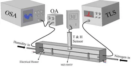
Fig. 2. Experimental set-up for measurement of changes in RH using different MZI-STFM waist-diameters.
interface in MNFs. The propagation constant for these hybrid modes can be calculated by solving equation 1. The V number can be expressed as:
V = U2+W2=2π
λ ·r·N A (3) MNFs experience single-mode operation when V <2.405 and a large portion of the power will propagate as the evanescent field outside the MNF for V 1 [22].
III. EXPERIMENTALSETUP
The Mach-Zehnder microfiber used in this experiment was fabricated from a standard SMF-28 optical fiber having a 9 μm core diameter and NA of 0.14. This optical fiber was tapered using a modified Mach-3 computer numerically-controlled (CNC) machine, which allowed for fabrication of a tapered fiber with propagation losses lower than 0.1 dB and a uniform waist diameter. This SMTF is illustrated in figure 1. A gradual reduction of the core and cladding diameters in a single-mode tapered-fiber (SMTF) will cause the evanescent fields to spread out into the cladding. These evanescent fields can reach the outer boundary for particular values of the SMTF waist diameter, since the fiber core is reduced to such an extent that its wave guiding effect is rendered negligible and light instead becomes guided by the interface between the cladding and the external medium. i.e. the whole reduced-diameter fiber forms the waveguide core. It is important to note that the circular symmetry of the original fiber is preserved, to a close approximation, throughout the SMTF, regardless of the diameter. The uniform-waist region lengths, L1and L2, for
all samples used in this experiment, as shown in figure1, were kept constant and equal to 20 mm - and the eventual waist diameters, d1 and d2, of the tapered fibers were changed in
this experiment - in order to investigate the humidity sensing dependence of the Mach-Zehnder microfiber interferometer, while using different waist diameters.
[image:3.612.51.301.558.658.2]Fig. 3. Transmission spectrum of the MZI-SMTF-1.
humidity and temperature chamber. A tunable laser source (YOKOGAWA AQ2211) is synchronized with the YOKOGAWA AQ6370B optical spectrum analyzer (OSA) to provide a wide supercontinuum laser source from 1440 nm to 1640 nm.
The laser source is connected to the OSA through the MZI-SMTF and the optical attenuator (OA) respectively to measure small changes in the humidity and temperature inside the humidity chamber. The humidity inside the chamber is controlled by balancing the amount of Nitrogen gas and humidity in the chamber. The temperature inside the chamber is controlled and tuned using the two electrical filaments located at the two corners of the chamber, as shown in figure 2. The temperature and humidity inside the chamber is measured by using a HANNA instruments HI thermos hygrometer Thermal and humidity sensor.
The free spectral range (FSR) is directly related to the length of the MZI-STMF, L, and it is about 0.55 nm for the both fabricated MZI-SMTF. The transmission spectrum of the MZI-STMF-1 shown in figure 3.
The first tapered area served to diffract the fundamental mode, and consequently to allow both the core and the cladding modes to become excited. Phase shifting within a physical length, L, of the MZI-SMTF is a result of the unequal effective refractive indices of the core and cladding modes. The different phase velocity of the fundamental and cladding modes cause a phase difference along the MZI-SMTF arm, due to MZI-SMTF’s length dependency and variation of wavelength of the guided light. The transmitted optical power of the interferometer will be minimized at certain wavelength and maximized at the others due to wavelength dependency of phase difference and phase velocity. The separation between consecutive peaks of a two-mode interferometer is given by λ = λ2/Ln
e, where λ indicates the source wavelength,
L is the length of the MZI-STMF - and ne symbolizes the effective refractive index difference between the core and cladding (external medium) modes.
IV. RESULTS ANDDISCUSSION
The transmission spectrum of the MZI-SMTF shown in figure 3 is the result of constructive and destructive interfer-ence between the cladding and core modes introduced into the MZI-SMTF, which generate an interference pattern in the MZI-SMTF. Since the two tapered regions, L1 and L2, act as
TABLE I
[image:4.612.315.558.341.587.2]PARAMETERS FOR THETWOFABRICATEDMZI-SMTFs
Fig. 4. Microscope image for MZI-SMTF-1: (a) d1 = 3.75 μm and
(b) d2=4.53μm.
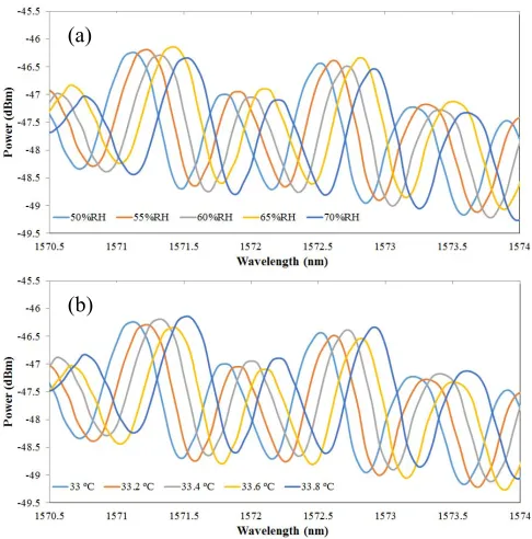
Fig. 5. (a) The displacement of the transmission spectrum for the MZI-SMTF-1 corresponding to changing (a) the RH and (b) the temperature.
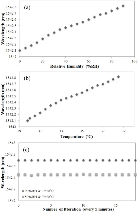
Fig. 6. Displacement of the MZI-SMTF-1 transmission spectrum for changing (a) RH and (b) temperature, inside the chamber. (c) Stability of the system at 50%RH and 90%RH, with the temperature of the chamber remaining unchanged. (d) The stability of the MZI-SMTF-1 transmission spectrum over a 90 minute period during which the humidity and temperature were maintained at 50%RH and 28 °C, respectively.
[image:5.612.56.290.49.625.2]Microscope images of the two tapered regions for MZI-SMTF-1 are shown in figure 4. The displacement of the transmission spectrum produced by changes in the refractive
Fig. 7. Microscope image for MZI-SMTF-2: (a) d1 = 3.55 μm and
(b) d2=2.09μm.
Fig. 8. The displacement of the transmission spectrum for the MZI-SMTF-2 corresponding to changing the: (a) RH and (b) temperature.
index that result from either humidity or temperature changes inside the humidity and temperature chamber surroundings of MZI-SMTF-1 are shown in figure 5. The displacement of the transmission spectrum was measured for humidity changing from 0%RH to 90%RH, with the temperature maintained constant - and temperature changing from 29 °C to 40 °C, with the RH kept constant.
Figure 5(a) illustrates the displacement of the transmission spectrum produced by changing the RH for five different values 50%RH, 55%RH, 60%RH, 65%RH and 70% RH -while the temperature in the chamber was kept constant at 30 °C. Figure 5(b) presents the displacement of the transmission spectrum produced by variation of the chamber temperature - for measured temperatures of 33 °C, 33.2 °C, 33.4 °C, 33.6 °C and 33.8 °C - while the humidity of the chamber was kept constant at 50%RH.
[image:5.612.322.551.207.436.2]Fig. 9. Displacement of the MZI-SMTF-2 transmission spectrum for changes in: (a) RH - and (b) temperature, inside the chamber. (c) Stability of the system in 50%RH and 90%RH while the temperature of the chamber remained unchanged.
the stability of the system at 50%RH and 90%RH, while the temperature of the chamber remained unchanged at about 28 °C. Figure 6(d) shows the stability of the MZI-SMTF-1 transmission spectrum over a 90 minute period - during which the humidity and temperature remained unchanged at 50%RH and 28 °C, respectively.
Figure 7 shows microscope images of the two tapered regions for MZI-SMTF-2. The displacement of the transmis-sion spectrum due to changes in the refractive index as a result of either humidity changing or temperature changing in the chamber surrounding MZI-SMTF-2 is shown in figure 8.
The displacement of the transmission spectrum was mea-sured for the humidity changing from 0%RH to 90%RH with the temperature remaining constant - and temperature changing from 29 °C to 40 °C with the RH remaining unchanged.
Figure 8(a) illustrates the displacement of the transmission spectrum produced by changing the RH for five different RH values - 50%RH, 55%RH, 60%RH, 65%RH and 70% RH, while the temperature in the chamber was maintained at 30 °C. Figure 8(b) presents the displacement of the transmission spectrum produced by variation of chamber temperature for the
measured temperatures of 33 °C, 33.2 °C, 33.4 °C, 33.6 °C and 33.8 °C, while the humidity of the chamber remained constant at 50%RH.
Figure 9 (a) and (b) show the displacement of the MZI-SMTF-2 transmission spectrum for changes in RH and temperature inside the chamber, respectively - as the refractive index of the medium surrounding the MZI-SMTF-2 changed. As can be seen, the humidity and temperature sensitivities of the MZI-SMTF-2 are 0.01 nm/%RH and 0.025 nm/0.1°C respectively. Figure 9(c) illustrates the stability of the system at 50%RH and 90%RH, while the temperature of the chamber remained unchanged at about 28 °C.
V. CONCLUSION
Two different waist-diameter, simple in-line, single-mode, tapered-fiber Mach-Zenhder interferometers (MZI-SMTF), with average waist diameters, (davg), of 4.05 and 2.89 μm respectively, have been fabricated. The fabricated MZI-SMTF performed based on interferometric techniques to operate the optical sensor where the transmission spectrum of the MZI-SMTF with respect to small changes in both the RH and the temperature was investigated. The performance of the sensors was investigated for probes with variable different taper waist-diameters. It was observed that the output trans-mission spectra shifted when the RH and temperature levels increased. The resolution achieved increases when the average waist diameter of the MZI-SMTF decreases. The humidity and temperature sensitivity values for MZI-SMTF-1 were 0.02 nm/%RH and 0.05 nm/0.1°C, respectively - while the humidity and temperature sensitivity values for MZI-SMTF-2 were 0.01 nm/%RH and 0.025 nm/0.1°C, respectively. These sensors are easy to fabricate, cheap - and compact. Although the MZI-SMTF’s waist diameters and lengths directly affect the sensor resolution, small fluctuation on MZI-SMTF’s waist diameters could be ignored. Moreover, fabricating such MZI-SMTF by utilizing accurate tapered machine will minimize the fabrication errors and cause the device reproducibility.
REFERENCES
[1] A. Sun, Z. Li, T. Wei, Y. Li, and P. Cui, “Highly sensitive humidity sensor at low humidity based on the quaternized polypyrrole composite film,” Sens. Actuators B, Chem., vol. 142, no. 1, pp. 197–203, 2009. [2] Q. Wu, Y. Semenova, P. Wang, and G. Farrell, “High sensitivity SMS
fiber structure based refractometer-analysis and experiment,” Opt. Exp., vol. 19, no. 9, pp. 7937–7944, 2011.
[3] T.-S. Cho, K.-S. Choi, D.-C. Seo, I.-B. Kwon, and J.-R. Lee, “Novel fiber optic sensor probe with a pair of highly reflected connectors and a vessel of water absorption material for water leak detection,” Sensors, vol. 12, pp. 10906–10919, 2012.
[4] J. Lou, Y. Wang, and L. Tong, “Microfiber optical sensors: A review,”
Sensors, vol. 14, no. 4, pp. 5823–5844, 2014.
[5] T. L. Yeo, T. Sun, and K. T. V. Grattan, “Fibre-optic sensor technologies for humidity and moisture measurement,” Sens. Actuators A, Phys., vol. 144, no. 2, pp. 280–295, 2008.
[6] S. K. Khijwania, K. L. Srinivasan, and J. P. Singh, “An evanescent-wave optical fiber relative humidity sensor with enhanced sensitivity,”
Sens. Actuators B, Chem., vol. 104, no. 2, pp. 217–222, 2005.
[7] Q. Zhou, M. R. Shahriari, D. Kritz, and G. H. Sigel, Jr., “Porous fiber-optic sensor for high-sensitivity humidity measurements,” Anal. Chem., vol. 60, no. 20, pp. 2317–2320, 1988.
[image:6.612.51.296.62.432.2][9] H.-N. Li, D.-S. Li, and G.-B. Song, “Recent applications of fiber optic sensors to health monitoring in civil engineering,” Eng. Struct., vol. 26, no. 11, pp. 1647–1657, Sep. 2004.
[10] S. Muto, O. Suzuki, T. Amano, and M. Morisawa, “A plastic optical fibre sensor for real-time humidity monitoring,” Meas. Sci. Technol., vol. 14, no. 16, p. 746, 2003.
[11] J. M. Corres, I. R. Matias, and F. J. Arregui, “Optical fibre humidity sen-sors using nano-films,” in Sensen-sors: Advancements in Modeling, Design
Issues, Fabrication and Practical Applications, S. C. Mukhopadhyay
and R. Y. M. Huang, Eds. Heidelberg, Germany: Springer-Verlag, 2008, pp. 153–177.
[12] J. M. Corres, J. Bravo, I. R. Matias, and F. J. Arregui, “Nonadiabatic tapered single-mode fiber coated with humidity sensitive nanofilms,”
IEEE Photon. Technol. Lett., vol. 18, no. 8, pp. 935–937, Apr. 15, 2006.
[13] J. M. Corres, F. J. Arregui, and I. R. Matías, “Sensitivity optimization of tapered optical fiber humidity sensors by means of tuning the thickness of nanostructured sensitive coatings,” Sens. Actuators B, Chem., vol. 122, no. 2, pp. 442–449, 2007.
[14] G. Brambilla, “Optical fibre nanowires and microwires: A review,”
J. Opt., vol. 12, no. 4, p. 043001, 2010.
[15] A. Stiebeiner, R. Garcia-Fernandez, and A. Rauschenbeutel, “Design and optimization of broadband tapered optical fibers with a nanofiber waist,” Opt. Exp., vol. 18, no. 22, pp. 22677–22685, 2010.
[16] T. A. Birks and Y. W. Li, “The shape of fiber tapers,” J. Lightw. Technol.
of, vol. 10, no. 4, pp. 432–438, Apr. 1992.
[17] J. Lou, L. Tong, and Z. Ye, “Modeling of silica nanowires for optical sensing,” Opt. Exp., vol. 13, no. 6, pp. 2135–2140, 2005.
[18] J. Wo et al., “Refractive index sensor using microfiber-based Mach–Zehnder interferometer,” Opt. Lett., vol. 37, no. 1, pp. 67–69, 2012.
[19] A. A. Jasim, S. W. Harun, K. S. Lim, B. M. A. Rahman, and H. Ahmad, “Microfibre Mach-Zehnder interferometer and its application as a current sensor,” IET Optoelectron., vol. 6, no. 6, pp. 298–302, Dec. 2012. [20] K. Okamoto, Fundamentals of Optical Waveguides. San Diego, CA,
USA: Academic, 2010.
[21] G. Y. Chen, M. Ding, T. P. Newson, and G. Brambilla, “A review of microfiber and nanofiber based optical sensors,” Open Opt. J., vol. 7, no. 1, pp. 32–57, 2013.
[22] L. M. Tong, J. Lou, and E. Mazur, “Single-mode guiding properties of subwavelength-diameter silica and silicon wire waveguides,” Opt. Exp., vol. 12, no. 6, pp. 1025–1035, Mar. 2004.
M. R. K. Soltanian received the B.Eng. and M.Eng. degrees in electronics and
telecommunications engineering. He is currently pursuing the Ph.D. degree in photonics engineering with the Photonics Research Centre, University of Malaya, Kuala Lumpur, Malaysia. He has published significant academic ISI papers, book, and book chapters. His research interests include lasers, optical communications, fiber optic sensors, plasmonics, silicon photonics, radio over fiber, nonlinear optics, and ultrafast lasers.
A. S. Sharbirin received the B.Sc. (Hons.) degree in pure physics from
Universiti Teknologi Malaysia. He is currently pursuing the Ph.D. degree in photonics with the Photonics Research Centre, University of Malaya. His research interest is in fiber lasers operating in the 2-μm wavelength region as well as the fabrication of fiber microstructures for applications in sensing.
M. M. Ariannejad received the B.Sc. degree in electronic engineering from
Tafresh University, Iran, in 2010, and the M.Sc. degree in microelectronic from University Kebangsaan Malaysia, in 2013. He is currently pursuing the Ph.D. degree with University Malaysia, Kuala Lumpur, Malaysia. He has published five academic publications since 2012 in optical waveguides, silicon photonics, and nanotechnology engineering.
I. S. Amiri received the B.Sc. degree in applied physics from the Public
University of Urmia, Iran, in 2001, the M.Sc. degree (gold medalist) in optics from University Technology Malaysia in 2009, and the Ph.D. degree in photonics in 2014. He has published over 400 academic publications since 2012 in optical soliton communications, laser physics, photonics, optics, and nanotechnology engineering. He is currently a Senior Lecturer with University Malaysia, Kuala Lumpur, Malaysia.
R. M. De La Rue (F’03) launched the U.K. semiconductor photonic crystal
research effort with TF Krauss in 1993 and contributed to the earliest demonstrations of photonic bandgap behavior in planar waveguide structures. His research has now evolved to cover nanophotonics in general, including photonic wire devices, compact lasers and microcavities, synthetic opals, inverse structures, and metamaterials. He has been involved in European-scale research activity through the FP4-SMILED, FP5-PICCO, and COST 268 and P11 projects. He is routinely in demand for invited presentations over four continents and is heavily involved in conference organization, e.g., Photonics Europe 2006 and CLEO-Europe 2007. He is a Fellow of REng, RSE, and IEE and has been involved in guided-wave optical device research for well over 30 years.
G. Brambilla received the M.Sc. (Hons.) degree in material engineering
from the Politecnico di Milano, Italy, and the Ph.D. degree in optoelectronics from ORC in 2002. He is a Professor with ORC, where he has been as a Researcher since 2002. He has published over 230 papers in international scientific journals/conferences, holds three patents, and co-authored four books on optical fibers. In the last few years, he has been involved in the fabrication of devices based on optical fiber nanowires, fiber tapers, and couplers, in the design and fabrication of rare earth doped scintillating fibers, and the design of special fibers and fiber combiners for the preservation of high brightness in fiber-diode coupled high-power fiber lasers. He is responsible for the fiberized component fabrication facilities, and most recently, he has been involved in the fabrication and characterization of silica and compound glass nanowires. In 2007, he received the prestigious Research Fellowship from the Royal Society.
B. M. A. Rahman leads the Research Group on Photonics Modeling,
City University, where he specialized in the development and use of the rigorous and full-vectorial numerical approaches, frequency domain modal solution approach, the beam propagation method, and time-domain approach, primarily based on the numerically efficient finite-element method. He has published more than 450 journals and conference papers in the areas of optical waveguides, integrated optics, single polarization guides, and pho-tonic devices, such as high-speed modulators and switches, power splitters, compact bend designs, polarization splitters, polarization rotators, polariza-tion controllers, spot-size converters, optical amplifiers, narrowband optical filters, nonlinear optical devices, optical structures supporting surface-plasmon modes, photonic crystal fibers, and THz waveguides. His journal papers have been cited more than 1900 times. He has received more than £6 million in research grants from the EPSRC, EU, British Council, and industries.
K. T. V. Grattan received the B.Sc. (Hons.) degree in physics from Queen’s
University Belfast in 1974, and the Ph.D. degree in laser physics. His doctoral research involved the use of laser-probe techniques for measurements on potential new laser systems. He was elected to the Royal Academy of Engineering and the U.K. National Academy of Engineering in 2008. He was elected as the President of the International Measurement Confed-eration in 2014, serving from 2015 to 2018. He is a Visiting Professor at several major universities in China, with strong links to Harbin Engineering University and the Shandong Academy of Sciences. His research interests have expanded to include the development and use of fiber optic and optical systems in the measurement of a range of physical and chemical parameters.
H. Ahmad received the Ph.D. degree in laser technology from the University