City, University of London Institutional Repository
Citation
:
Kloukinas, C. and Ozkaya, M. (2012). XCD – Simple, Modular, Formal Software
Architectures (TR/2012/DOC/01). .
This is the published version of the paper.
This version of the publication may differ from the final published
version.
Permanent repository link:
http://openaccess.city.ac.uk/4122/
Link to published version
:
TR/2012/DOC/01
Copyright and reuse:
City Research Online aims to make research
outputs of City, University of London available to a wider audience.
Copyright and Moral Rights remain with the author(s) and/or copyright
holders. URLs from City Research Online may be freely distributed and
linked to.
City Research Online:
http://openaccess.city.ac.uk/
[email protected]
Christos Kloukinas
Mert Ozkaya
Department of Computing
Technical Report Series
CONTENTS
I Introduction 2
I-A Complex Connectors for Architectural Analysis . . . 2
I-B Connector Role Strategies for Control and Design Decisions . . . 2
I-C Design by Contract . . . 3
I-D Case Study . . . 3
II XCD Components 3 II-A Extending Design by Contract – Different Contract Types . . . 3
II-B Extending Design by Contract – Service Consumer Contracts . . . 4
II-C Testing Architectural Components . . . 5
III XCD Connectors 6 III-A Glue-less Connectors . . . 6
III-B Wrapper-like Connectors . . . 6
III-C Decentralized Connectors . . . 6
III-D Fundamental Connector Properties . . . 6
III-E Centralized Connectors . . . 7
IV System Control and Design Decisions – Role Strategies 8 V Evaluation 8 VI Related Work 9 VII Conclusions 10 References 11 LIST OFFIGURES 1 Thesitdown/arise(iSA) interface . . . 3
2 Seat component specification . . . 4
3 Seat component specification in pseudo-JML . . . 5
4 Philosopher component specification . . . 5
5 Decentralized dining philosophers connector . . . 7
6 Centralized dining philosophers connector . . . 7
7 Philosopher role strategies . . . 8
8 Butler role strategies . . . 8
9 System configurations . . . 9
LIST OFTABLES I Different decentralized strategy combinations . . . 10
Christos Kloukinas, Mert Ozkaya School of Informatics City University London
London, U.K.
Email: [email protected], [email protected]
Abstract—Connector-Centric Design (XCD) is a new ap-proach for specifying software architectures that focuses on the use of complex connectors. In XCD simple intercon-nection mechanisms like procedure-calls, event-buses, etc. are abstracted and components take a second place. XCD aids the clear separation in a modular manner of the high-level functional, interaction, and control system behaviour, thus increasing the reusability of both components and connectors. As such, XCD allows designers to experiment with different interaction behaviours (connectors), without having to modify the functional behaviour specifications (components). It further allows designers to experiment with different control behaviours (“role strategies”), without modifying components or connectors.
Inspired by JML, XCD follows a formal, Design-by-Contract approach, describing behaviour through simple pre/post-conditions, which should make it easier for prac-titioners to use. XCD extends Design-by-Contract so as to separate contracts into functional and interaction sub-contracts, and so as to allow service consumers to specify their own contractual clauses. The specifications of XCD connectors are completely decentralized (e.g., no “connector glue”) to facilitate their realization and their refinement for further formal analyses.
Keywords-Software architecture; Modular specifications; Separation of functional interaction and control behaviours; Design by contract.
I. INTRODUCTION
Architectural descriptions of systems are extremely valuable for communicating high-level system design as-pects and the different solutions that have been evaluated for meeting system-wide, non-functional properties. Re-searchers have advocated the need for components and connectors to be first-class architectural entities from the very beginning [1], [2]. However, the support for complex connectors is minimal in languages used in practice cur-rently, e.g., AADL [3], SysML [4]. They mostly rely on simple interconnection mechanisms like procedure-calls and provide no support for specifying complex connectors, focusing instead all their attention upon components. The end result is that architectures end up more like low-level designs [5]. At the same time components have to incorporate specific interaction protocols thus reduc-ing their reusability. Worse yet, when the component specifications do not explicitly specify which protocols they have been designed for, we have the problem of “architectural mismatch” [6], i.e., the inability to compose seemingly compatible components, due to the (undocu-mented) assumptions these make on their interaction with their environment.
The Connector-Centric Design (XCD) approach takes
Wirth’s equation “Algorithms + Data Structures = Pro-grams” and advocates that at the architectural level we have “Connectors + Components = Systems”, with connectors being essentially decentralized algorithms and components the equivalent to data structures [7]. XCD fo-cuses on improving the structural representation of formal architectural specifications, so as to aid both their develop-ment and their formal analysis. Connectors are at the very centre of XCD, since it is them that are responsible for meeting system-wide, non-functional requirements that no component can meet, such as reliability, performance, etc.
A. Complex Connectors for Architectural Analysis
Let us consider n electrical resistors, r1,· · ·,rn. When
using a sequential connector (→), the overall resistance is computed asR→(N,{Ri}iN=1) =∑Ni=1Ri. If using a parallel
connector (k) instead, it is computed asRk(N,{Ri}Ni=1) =
1/∑Ni=11/Ri. So the interaction protocol (connector) used
is the one that gives us the formula we need to use to analyze it – if it does not do so, then we are probably using the wrong connector abstraction. The components (rj) are simply providing some numerical values to use in
the formula, while the system configuration tells us which specific value (n,rj) we should assign to each variable (N,
Ri) of the connector-derived formula. By simply
enumerat-ing the wires between resistors, as languages like AADL do, we miss the forest for the trees. Analysis becomes difficult and architectural errors can go undetected until later development phases.
B. Connector Role Strategies for Control and Design Decisions
void sitdown(ID caller)throws(NullIDEX); void arise(ID caller)throws(NullIDEX,
WrongCallerEX,
InteractionEX); Figure 1: Thesitdown/arise (iSA) interface
(++i) may potentially change the value of the first one (i). So we can obtain eitherfoo(1,2) or foo(2,2). The C language specification does not want to specify a specific order for evaluating parameters, explicitly under-specifying the procedure-call connector specification. If compilers have multiple cores at their disposal they are al-lowed to evaluate parameters in parallel, instead of having to evaluate each one in a specific sequential order. The C language specification allows compilers to apply different evaluation strategies on the caller role by delaying this design decision until the optimal choice can be made, based on the call context and the implementation costs of the available strategies.
C. Design by Contract
Inspired by JML’s [9] developer friendliness, XCD follows Design by Contract (DbC) [10] too. XCD extends DbC in two ways. First, it separates the functional behaviour of a component from its minimal interaction requirements. Second, it allows service consumers to specifycontractual clauses of their own.
D. Case Study
We demonstrate the different features of XCD through the dining philosophers problem, chosen because different solutions exist for it – both with no centralized control and with centralized control (a “butler”). We show how a designer can specify the system with different connectors (for decentralized and centralized control), without chang-ing the component specifications, and then specify differ-ent control policies, without changing the specifications of either the connectors or the components.
We consider first component specifications in XCD, concentrating then on connectors – their specification in a decentralized manner that facilitates their implemen-tation and analysis, and the fundamental properties that a complex connector should provide. We then consider role strategies for expressing control and other design decisions, and present an evaluation of the approach before discussing related work and concluding.
II. XCD COMPONENTS
Figure 1 shows the interface implemented by the Seat component – the Fork one (iGP) has methods get and put with similar signatures. Method sitdown
throws a NullIDEX exception, while arise also throws
WrongCallerEX when the Seat is occupied by someone
that is not the caller. However,arisethrows yet another exception – the enigmatic InteractionEX. Components throw this special exception when theirminimal interac-tion constraints (rather than functional ones) have been violated.
A. Extending Design by Contract – Different Contract Types
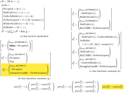
Figure 2a shows the Seat component specification. It defines itsdatavariable set (D) and some helperpredicates (preds). Then it defines two sets of ports, (Ps, Pp), for the “socket” and “plug” ports respectively, i.e., the ones providingsome interface and these using some interface – what in CORBA are facets and receptacles. Finally, it defines sets of functional (φ) and interaction (χ) constraints, shown in Figure 2c and 2b respectively.
Constraints all follow the syntax (port-expr., method,
pre-condition, post-condition) and are grouped ([]) by the (port-expr., method) pair they apply to. They are labelled as (s|a)(φ|χ) – for sitdown/arise (s|a) and for
functional/interaction (φ|χ). So in sφ1, pseat’s sitdown
pre-condition is ¬NullCaller(c) and HolderIsCaller(c) its post-condition. This is a JML “normal behaviour”, unlike sφ2 that throws a NullIDEX exception if the pre-condition NullCaller(c) is true. Constraints aφ1, aφ2 are similar ones for arise, while aφ3 covers the case when the pre-condition is¬CallerIsHolder(c). In that case, the post-condition requires that a WrongCallerEXexception is thrown.
This last constraintaφ3introduces the difference between functional and (minimal) interaction constraints. Method
arise accepts calls where the caller is not the holder
and throws an exception, whilesitdowndoes not specify anything about this. According to sφ1 it seems it simply replaces Seat’s holder with the caller. However, this is captured in Figure 2b, through Seat’sminimal interaction constraints. Constraint sχ1 asks that sitdown be delayed untilOccupiedis false. This is expressed using the “when” keyword as in JML [11], though in XCD functional constraints are not allowed to use it. To relate it to JML, one can think of it as a “normal” interaction behaviour, describing a method’s acceptable concurrent behaviours. For all “normal” interaction constraints of components, the post-condition is always True. Figure 2b also specifies the minimal interaction constraints of arise. Constraint aχ1 states that calling arise on an occupied Seat is ac-ceptable. Constrainta2χ, however, states that callingarise
on an unoccupied Seat, results in an InteractionEX
exception (which functional constraints cannot use). This is a situation that Seat does not know how to deal with – similar to calling a method on a component without having initialized it first. The real meaning of anInteractionEX
exception is that the component behaviour becomes un-defined.
<D=ID h:=⊥ , preds=
Occupied= (h6=⊥),
NullCaller(c) = (c=⊥),
CallerIsHolder(c) = (c=h),
NoVarAssigned=∀v∈D(¬assigns(v))
HolderIsCaller(c) = (h0=c),
NoHolder= (h0=⊥),
,
Ps={piSA
seat},Pp=/0,φ,χ>
(a) Seat top-level specification
s χ 1 =
pseat,sitdown(c),
when(¬Occupied),
True
aχ1=
pseat,arise(c), Occupied,
True
a2χ=
pseat,arise(c),
¬Occupied,
InteractionEX ∧NoVarAssigned
(b) Seat interaction constraints (χ)
sφ1=
pseat,sitdown(c),
¬NullCaller(c),
HolderIsCaller(c)
sφ2=
pseat,sitdown(c), NullCaller(c),
NullIDEX∧NoVarAssigned
aφ1 =
pseat,arise(c),
¬NullCaller(c)∧CallerIsHolder(c),
NoHolder
∧ ∀v∈(D\ {h})(¬assigns(v))
aφ2 =
pseat,arise(c), NullCaller(c),
NullIDEX∧NoVarAssigned
aφ3 =
pseat,arise(c),
¬CallerIsHolder(c),
WrongCallerEX∧NoVarAssigned
(c) Seat functional constraints (φ)
pre(sχ1)→V
pre(sφ1)→post(sφ1)
pre(sφ2)→post(sφ2)
pre(a χ 1)→
V
pre(aφ1)→post(aφ1)
pre(aφ2)→post(aφ2)
pre(aφ3)→post(aφ3)
pre(aχ2)→post(aχ2)
[image:6.595.55.494.73.403.2](d) Combination of functional and interaction pre-/post-conditions
Figure 2: Seat component specification
is satisfied, the functional constraints should also be sat-isfied.
If one specified contracts in the usual manner, they would need F×I cases in the worst case, combining F functional and I interaction constraints, e.g., forarise: Case 1:pre(aχ1)∧pre(aφ1)→post(aφ1)
Case 2:pre(aχ1)∧pre(aφ2)→post(aφ2)
Case 3:pre(aχ1)∧pre(aφ3)→post(aφ3)
Case 4:pre(aχ2)→post(a2χ)
Repeating “pre(a1χ)” each time makes specifications more difficult to read than they need be and much easier to get wrong. The introduction of the (minimal) interaction constraintsimposesa much cleaner and modular manner. Figure 3 shows how the Seat component specification would look like in pseudo JML. Non JML parts are preceded by two “@” characters instead of one. There
are two new groups “InteractionConstraints” and “FunctionalConstraints”, and the new “UNDEFINED_
-BEHAVIOUR” type to be used in the former group only. Key-word when cannot be used in FunctionalConstraints
andLetconstructs (in Figure 3a) introduce new predicates.
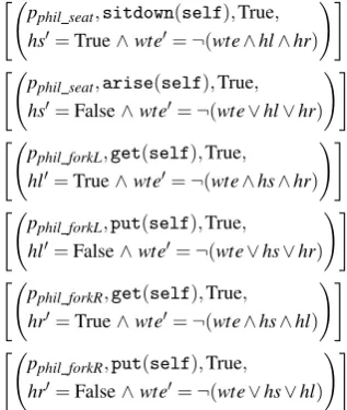
B. Extending Design by Contract – Service Consumer Contracts
In DbC service providers specify pre-/post-conditions for each method they provide but service consumers cannot express their own contractual clauses. Indeed,
programming languages do not allow service consumers to even declare the services they consume. However, in component models like CORBA one declares both the services it provides (our sockets) and these it consumes (our plugs). Here weextend DbC further, so that we can specify contracts for consumed services as well. This is done for the Philosopher in Figure 4a. Philosopher has a Boolean variablewte (“want to eat”), and three more (hs, hl, hr) to state whether it has a Seat, a left and a right Fork respectively. These change their values according to its functional constraints in Figure 4c,which apply when a method does not throw an exception – that is why we call them “normal”. On exceptions the Philosopher does not update its data. Keyword selfdenotes the IDof the component instance.
The Philosopher interaction constraints in Figure 4b statewhen services may be requested from others. These constraintsspecify no resource acquisition/release order. Philosopher is free to acquire a Seat after both Forks or in between them. In fact, it can even acquire or release a resource multiple times. The constraints state that when it wants to eat it will need to acquire all three resources, without releasing any of them. When it does not want to eat, it will release all three resources (again in some unspecified order), without attempting to re-acquire any of them until all of them have been released. These constraints were added so that the system can deadlock –
1/*@ instance model ID holder; 2 @ initially holder == NullID; 3 @@Let Occupied
4 @@ \old(holder) != NullID; 5 @@Let NullCaller(c) c == NullID; 6 @@Let CallerIsHolder(c)
7 @@ c == \old(holder); 8 @@Let HolderIsCaller(c) 9 @@ holder == c;
10 @@Let NoHolder holder == NullID; 11 @*/
(a) Specification of component variables
1/*@@InteractionConstraints 2 @@ public normal_behavior 3 @@ when !Occupied; 4 @@FunctionalConstraints 5 @public normal_behavior 6 @ requires !NullCaller(c); 7 @ ensures HolderIsCaller(c); 8 @ assignable holder; 9 @also
10 @ public exceptional_behavior 11 @ requires NullCaller(c); 12 @ signals (NullIDEX) true; 13 @ assignable \nothing; @*/ 14void sitdown(ID c);
(b) Specification ofsitdownconstraints
1/*@
2 @@InteractionConstraints 3 @@ public normal_behavior 4 @@ requires Occupied; 5 @@also
6 @@ public UNDEFINED_BEHAVIOR 7 @@ requires !Occupied; 8 @@FunctionalConstraints 9 @public normal_behavior 10 @ requires !NullCaller(c) 11 @ && CallerIsHolder(c); 12 @ ensures NoHolder; 13 @ assignable holder; 14 @also
15 @ public exceptional_behavior 16 @ requires NullCaller(c); 17 @ signals (NullIDEX) true; 18 @ assignable \nothing; 19 @also
20 @ public exceptional_behavior 21 @ requires !NullCaller(c) 22 @ && !CallerIsHolder(c); 23 @ signals (WrongCallerEX) true; 24 @ assignable \nothing;
25 @*/
26void arise(ID c);
[image:7.595.50.530.299.601.2](c) Specification ofariseconstraints
Figure 3: Seat component specification in pseudo-JML
<D=
(
Bool wte:=True,Bool hs:=False,
Bool hl:=False,Bool hr:=False )
,
preds=/0,Ps=/0,
Pp={piSA
phil seat,p iGP
phil forkR,p iGP
phil forkL},φ,χ>
(a) Philosopher top-level specification
[(pphil seat,sitdown(self),when(wte),True)] [(pphil seat,arise(self),when(¬wte),True)]
[(pphil forkL,get(self),when(wte),True)] [(pphil forkL,put(self),when(¬wte),True)] [(pphil forkR,get(self),when(wte),True)] [(pphil forkR,put(self),when(¬wte),True)]
(b) Philosopher interaction constraints (χ)
"
pphil seat,sitdown(self),True, hs0=True∧wte0=¬(wte∧hl∧hr)
!#
"
pphil seat,arise(self),True, hs0=False∧wte0=¬(wte∨hl∨hr)
!#
"
pphil forkL,get(self),True, hl0=True∧wte0=¬(wte∧hs∧hr)
!#
"
pphil forkL,put(self),True,
hl0=False∧wte0=¬(wte∨hs∨hr)
!#
"
pphil forkR,get(self),True, hr0=True∧wte0=¬(wte∧hs∧hl)
!#
"
pphil forkR,put(self),True,
hr0=False∧wte0=¬(wte∨hs∨hl)
!#
(c)“Normal”functional constraints (φ)
Figure 4: Philosopher component specification CP1=∀m.
_
n pre(mχ
n) (1) CP2=∀m.
^
k pre(mχ
k)→
_
n pre(mφ
n) !
(2)
CP3=∀m. ^
k
pre(m χ k)→
^
n
pre(mφn)→
post(mφn)
^
j6=n
pre(mφj)→post(mφj)
(3)
otherwise, Philosopher can release the resources it holds when those it needs are not available. It is exactly for this that we have introduced functional and interaction constraints to plug ports. Without them designers cannot express the constraints under which the service providers must operate. They are essentially a service’s “environ-ment model”.
C. Testing Architectural Components
Following the constraint semantics in Figure 2d, one needs to check that (CP1) the interaction pre-conditions are complete; and whenever the normal interaction pre-conditions are satisfied that (CP2) the functional
pre-conditions are complete; and (CP3) the functional con-straints are consistent.
[image:7.595.304.463.321.509.2]completeness of the functional pre-conditions only when the method is eventually executed, in which case thewhen condition should hold.
III. XCD CONNECTORS
Fork being similar to Seat we can now specify the system connectors. If we opt for something like procedure-call, event-bus, etc. then we are specifying our system at a very low-level. The extra details obfuscate the design, making it difficult to identify the high-level interaction protocols, thanks to which the system achieves its non-functional requirements. This is why XCD focuses instead on complex connectors. These connectors consist of a set of roles, each one with a set ofport variables. Role port variables are assumed by some component ports, as specified by the architectural configuration.
A. Glue-less Connectors
XCD connectors differ from those of Wright [12], since XCD employs no “glue” element for coordinating role be-haviours. The glue is problematic for a number of reasons. First, theglue is a choreography, so one needs to realize it as a set of individual services (i.e., role implementations) composed in parallel. But [13], [14] have shown that the choreography realization problem is undecidablein general. Second, if we need to consider multiple instances of some role, then we need to manually specify in the glue all the acceptable composed behaviours of these instances. For example, when considering a market system with one consumer and two merchants in [15], the glue describes all possible interactions of the three roles – thisdoes not scale. Finally, the glue hinders the architectural analysis for further non-functional requirements, such as reliability, performance, real-time behaviour, etc. It introduces an artificial centralization pointin the connector, even if the protocol that is being represented by the connector does not have such a centralization point, e.g., the procedure-call. This makes analysis more difficult, since now one has to consider the real centralization points while ignor-ing the fictitious ones (the glue elements of the various connectors). It also makes the modelling more difficult to validate. For example, in [15] the authors perform a probabilistic analysis of a market system, assigning a rate R1 to all transitions between the consumer role and
the glue and a rate R2 to all transitions among the glue
and the merchant roles. However, transitions between the consumer and the glue represent in reality requests from the consumer to the merchants, as well as responses from the merchants to the consumer. The transitions among the glue and the merchants also represent the same requests and responses. We fail to see how these rate assignments can be justified – in our view, the glue complicates the situation so much that it is very easy to produce models that are difficult to understand and map to reality.
B. Wrapper-like Connectors
In [12], a component should implement the roles it assumes,L(Comp)⊆L(Role). This seems too constrain-ing and limitconstrain-ing component reusability. Instead, XCD
components focus on implementing just the minimum interaction constraints that they need to operate correctly. The roles they assume act as a sort of wrapper, control-ling their behaviour so that it meets the expected role behaviours.
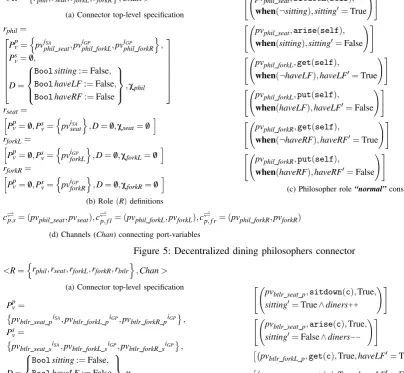
C. Decentralized Connectors
Figure 5 shows the specification of a complex De-centralized connector for the dining philosophers. The connector defines a set of roles and interaction channels (Figure 5a). The specifications of the roles are shown in Figure 5b. Each of them has four constituent parts: a set of plug port variables (Ppv), a set of socket port variables (Psv), a set of role data variables (D), and a set of interaction constraints (χ). Roles rseat, rforkL, and
rforkR, have no data or interaction constraints. Role rphil
uses variables to keep track of the state of resources and to control it through its interaction constraints in Figure 5c so that it only acquires resources when they are free and releases them when it already holds them. These constraints modify role variables only when the respective methods do not raise an exception. Channels in Figure 5d state which role port variables are linked to each other – all the channels we use are rendez-vousones.
It should be noted that this connector is not describing the full system configuration. If there areninstances of the Philosopher, Seat, and Fork components in the system then there should beninstances of the Decentralized connector as well, since a single connector instance can only connect one Philosopher, with one Seat and two Forks.
D. Fundamental Connector Properties
There aretwo fundamental connector safety properties: (XP1) local deadlock-freedom; and (XP2) interaction
exception-freedom. Local deadlock-freedom (XP1) re-quires each connector role to not cause its component to deadlock by constraining it too much. This can be checked at a local level by showing that L(Compk
Role)⊆L(Role).
However, interaction exception-freedom (XP2) is a connector-level property. It requires that component socket ports never throw an interaction exception, no matter how the component plug ports behave. This can be checked by composing the connector with the corresponding com-ponents that assume its roles,while setting all interaction pre-conditions of component plug ports toTrue (i.e., those in Figure 4b). Doing so allows us to explore all possible interaction patterns that the connector roles allow for the components and verify that interaction exceptions have been rendered impossible by it.
Of course, these two safety properties do not guar-antee that the connector as a whole (or for that matter the system) will be deadlock-free. Nevertheless we do not view this as being problematic because we believe that connector-level deadlock-freedom is best met through external role strategies as discussed in section IV.
<R=
rphil,rseat,rforkL,rforkR ,Chan>
(a) Connector top-level specification
rphil=
Ppv=
n
pviSA
phil seat,pv iGP
phil forkL,pv iGP
phil forkR
o
,
Ps v=/0, D=
Boolsitting:=False,
BoolhaveLF:=False,
BoolhaveRF:=False
,χphil
rseat=
h
Ppv=/0,Psv=
n
pviSA
seat
o
,D=/0,χseat=/0
i
rforkL=
h
Ppv=/0,Psv=
n
pviGP
forkL
o
,D=/0,χforkL=/0
i
rforkR=
h
Ppv=/0,Psv=
n
pviGP
forkR
o
,D=/0,χforkR=/0
i
(b) Role(R)definitions
"
pvphil seat,sitdown(self),
when(¬sitting),sitting0=True !#
"
pvphil seat,arise(self),
when(sitting),sitting0=False !#
"
pvphil forkL,get(self),
when(¬haveLF),haveLF0=True !#
"
pvphil forkL,put(self),
when(haveLF),haveLF0=False !#
"
pvphil forkR,get(self),
when(¬haveRF),haveRF0=True !#
"
pvphil forkR,put(self),
when(haveRF),haveRF0=False !#
(c) Philosopher role“normal”constraints (χphil)
c*)p,s= (pvphil seat,pvseat),c * )
p,f l= (pvphil forkL,pvforkL),c * )
p,f r= (pvphil forkR,pvforkR)
[image:9.595.51.456.87.460.2](d) Channels (Chan) connecting port-variables
Figure 5: Decentralized dining philosophers connector
<R=nrphil,rseat,rforkL,rforkR,rbtlr
o
,Chan>
(a) Connector top-level specification
Ppv=
pvbtlr seat piSA,pv
btlr forkL piGP,pvbtlr forkR piGP , Psv=
pvbtlr seat siSA,pvbtlr forkL siGP,pvbtlr forkR siGP ,
D=
Boolsitting:=False,
BoolhaveLF:=False,
BoolhaveRF:=False
,χbtlr
(b)LocalButler role (rbtlr) specification
Ppv=/0,Psv=/0,Dshared={Intdiners:=0}, χbtlrshared=/0
(c)SharedButler role specification
"
pvbtlr seat p,sitdown(c),True, sitting0=True∧diners++
!#
"
pvbtlr seat p,arise(c),True,
sitting0=False∧diners --!#
pvbtlr forkL p,get(c),True,haveLF0=True
pvbtlr forkL p,put(c),True,haveLF0=False
pvbtlr forkR p,get(c),True,haveRF0=True
pvbtlr forkR p,put(c),True,haveRF0=False
(d) Butler role“normal”constraints (χbtlr)
c*)p,bs= (pvphil seat,pvbtlr seat s),c * )
bss,bsp= (pvbtlr seat s,pvbtlr seat p),c * )
bsp,s= (pvbtlr seat p,pvseat), c*)p f l,b f ls= (pvphil forkL,pvbtlr forkL s), · · ·
[image:9.595.53.486.212.592.2](e) Channels (Chan) connecting port-variables
Figure 6: Centralized dining philosophers connector
E. Centralized Connectors
Figure 6 shows a Centralized connector for the din-ing philosophers. Unlike the Decentralized connector of Figure 5, this one introduces a further role, the Butler (rbtlr). The Butler sits among the other roles, as the
connector channels (Figure 6e) indicate, and observes the interactions of the other roles. Unlike the other roles, the Butler has two parts – alocaland ashared one, shown in Figure 6b and 6c respectively. While each Centralized connector instance creates a new local Butler role part, the shared part of the Butler role will be unique and shared among all instances of the Centralized connector, just like
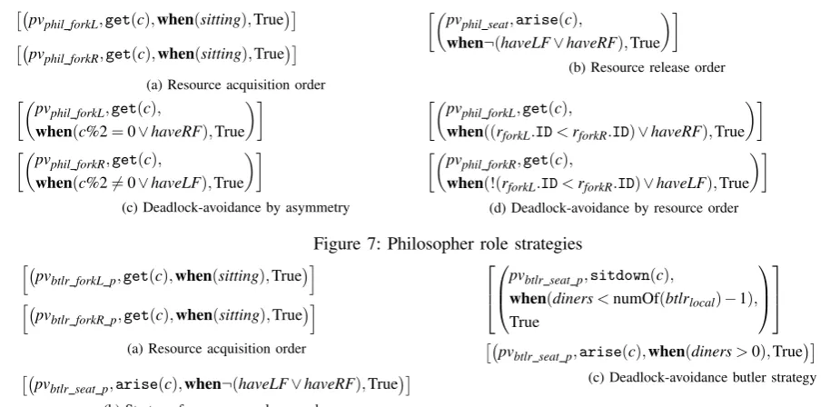
pvphil forkL,get(c),when(sitting),True
pvphil forkR,get(c),when(sitting),True
(a) Resource acquisition order
pv
phil seat,arise(c),
when¬(haveLF∨haveRF),True
(b) Resource release order
pv
phil forkL,get(c),
when(c%2=0∨haveRF),True
pvphil forkR,get(c),
when(c%26=0∨haveLF),True
(c) Deadlock-avoidance by asymmetry
pv
phil forkL,get(c),
when((rforkL.ID<rforkR.ID)∨haveRF),True
pv
phil forkR,get(c),
when(!(rforkL.ID<rforkR.ID)∨haveLF),True
[image:10.595.49.512.74.298.2]
(d) Deadlock-avoidance by resource order
Figure 7: Philosopher role strategies
h
pvbtlr forkL p,get(c),when(sitting),True
i
h
pvbtlr forkR p,get(c),when(sitting),Truei
(a) Resource acquisition order
pvbtlr seat p,arise(c),when¬(haveLF∨haveRF),True
(b) Strategy for resource release order
pvbtlr seat p,sitdown(c),
when(diners<numOf(btlrlocal)−1),
True
pvbtlr seat p,arise(c),when(diners>0),True
(c) Deadlock-avoidance butler strategy
Figure 8: Butler role strategies
IV. SYSTEMCONTROL ANDDESIGNDECISIONS– ROLESTRATEGIES
XCD advocates the underspecification of connec-tors. Additional interaction properties are to be imposed throughmodular role strategies[7]. These can enforce an action order, e.g., that Seat is acquired before the Forks, or render the system deadlock-free. Deadlock-freedom itself can usually be achieved through different techniques. Instead of hard-coding one in the connector, XCD allows designers to re-use the same connector specification and experiment with different strategies for it in a modular fashion.
Figure 7 shows examples of such strategies for the Philosopher role. The strategy in Figure 7a forces Seat to be acquired before the Forks, while that of Figure 7b forces Forks to be released first. Then the asymmetry strategy in Figure 7c avoids deadlocks by picking a different Fork when the ID of the caller is odd or even. The strategy in Figure 7d also avoids deadlocks but does so by always acquiring the Fork with the smallestIDfirst. In the Centralized connector we can also employ strategies on the Butler role, as shown in Figure 8. The strategies in Figure 8a and 8b are similar to those in Figure 7a and 7b respectively – only they are applied to the Butler role instead of the Philosopher. Finally, Figure 8c shows how to avoid deadlocks by preventing Philosophers from ever filling the table.
V. EVALUATION
We have manually encoded these architectural specifi-cations in the FSP process algebra [16] and have verified them automatically. In the FSP encoding each port and port variable are represented by one process that estab-lishes the interaction constraints of their methods and for components we also employ one process per port method to establish its functional constraints. In total, we con-sidered 12 different configurations for the decentralized
system in Figure 9a and 4 different configurations for the centralized system Figure 9b, using different combinations of strategies. In all these cases our models remained the same, with the only difference being the enabling/disabling of strategies.
The different role strategies defined in Figure 7 and Figure 8 allow designers to easily experiment with control-ling their system and evaluating different design decisions early on. Thus, XCD aids designers to decide on, and explicitly document, the relative importance of the various system properties and the specific solutions they have provided for each. XCD also makes it easier to experiment with different strategies and configurations of strategies, as these are represented explicitly and independently of connectors.
Table Ia shows results from combinations of the two ordering strategies of Figure 7a and Figure 7b with the asymmetry strategy of Figure 7c and the resource-based strategy of Figure 7d, for a system with 2 philosophers. Table Ib, Table Ic, and Table Id show results for 3, 4, and 5 philosophers respectively. We used LTSA v. 2.2 with 7000 MB of RAM. Surprisingly, we see that the best state space reduction for two strategies is obtained when combining the two strategies that constrain the acquisition and release order of resources (64%, 80%, 88%, and 93% respectively), even though these do not render the system deadlock-free. These reductions are almost the double of those achieved by the strategies for deadlock-freedom on their own (33%, 40%, 51%, and 58% respectively).
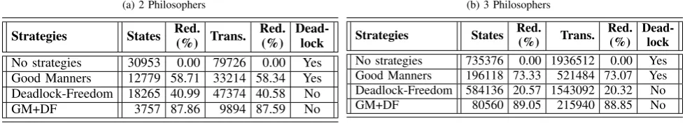
Table IIa shows results from the combined “Good Manners” strategy of Figure 8a and Figure 8b with the deadlock-free strategy of Figure 8c, for a system with 2 philosophers. Table IIb shows results for these strategies for 3 philosophers respectively.
It is not necessarily true that a designer should choose to apply a deadlock-freedom strategy first. In fact, the results obtained by the two deadlock-freedom strategies for 2 and
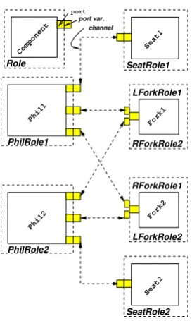
PhilRole1
Phil1
PhilRole2
Phil2
Seat1
SeatRole1
RForkRole2 LForkRole1
LForkRole2 RForkRole1
SeatRole2
Fork1
Fork2
Seat2
Role
Component
port port var.
channel
(a) Decentralized configuration
PhilRole1
PhilRole2
Butler(Local)Role1
Butler(Local)Role2
SeatRole1
RForkRole2 LForkRole1
LForkRole2 RForkRole1
SeatRole2
Butler Phil1
Phil2
Seat2 Fork2 Fork1 Seat1
Butler(Shared)Role
[image:11.595.63.200.76.304.2](b) Centralized system configuration
Figure 9: System configurations
3 philosophers in Table Ia and Table Ib is a reason for not doing so is – they are identical. So for designers to argue why they have chosen one strategy over the other, they have to consider a larger system, with 4 philosophers and possibly with 5. There the two strategies produce different results (a 51% versus 48% reduction and a 58% versus a 55% one respectively). However, checking a larger system is far more expensive and may lead to state-space explosion. So we can see that constraining first with some strategies which do not meet any critical properties, as with the acquisition and release ordering strategies, is a sensible step for reducing the overall state-space. It allows designers to explore larger instances of the system, which may potentially help identify further problems, opportunities for optimization, or simply provide evidence for choosing among alternative strategies for meeting a particular property, as it does here. Designers can then remove some of the non-critical strategies, if they need to use the extra degrees of freedom for meeting other critical properties, e.g., performance.
VI. RELATEDWORK
Research in software architectures identified the need for a first-class connector notion from the very beginning [1], [2]. The problems created by the non-documentation of protocols was also identified early on in [6] and a formalization of connectors was presented in [12] shortly after that – a formalization that is still being used today, e.g., [17], [18]. Compared to [12], XCD adds the extra element ofrole strategy, and the additional constraint that connectors and strategies shouldnot have a glue.
Work which has been done at identifying different types of connectors [19], [20] has tended to focus at cataloguing and specifying basic interaction mechanisms, e.g., procedure calls, event buses, etc., especially since
these were needed to base upon them more complex con-nectors. However, the use of basic interaction mechanisms as connectors in an architectural specification makes it difficult to understand what the real protocols in the system are and leads to system specifications that are at a very low level of abstraction, as is the case with AADL [5]. Indeed, designers are forced to incorporate the behaviour of the more complex connectors they wish to use into their components, decreasing their re-use potential and increasing the chance of architectural mismatch [6]. In fact, the presence of low-level connectors [19], [20] in a system architecture should alert designers that they have a potential problem. That is, they haveover-designed the architectural description and/or have failed to describe the general protocols that are supposed to be used among their components in a way that is sufficiently abstract, and therefore understandable and analyzable. Blackboards, event buses, tuple spaces, etc., are low-level interconnec-tion mechanisms that give precious little informainterconnec-tion on what interaction protocols a system uses and how these meet its non-functional requirements.
Languages used by practitioners suffer from this prob-lem in particular. A connector in UML 2.0 is just a UML association, so architects must use modelling elements other than UML connectors to describe connectors [21]. AADL [3] only supports certain specific, basic connector types and does not offer the possibility to define more complex connector types, while SysML [4] does not support connectors at all.
Table I: Different decentralized strategy combinations
(a) 2 Philosophers
Strategies States Red.
(%) Trans. Red.
(%)
Dead-lock No strategies 505 0.00 1104 0.00 Yes Acq(uisition) 303 40.00 628 43.12 Yes Rel(ease) 345 31.68 732 33.70 Yes As(ymmetry) 335 33.66 708 35.87 No Acq./Rel. 179 64.55 352 68.12 Yes Acq./As. 245 51.49 504 54.35 No Rel./As. 205 59.41 412 62.68 No Acq./Rel./As. 133 73.66 256 76.81 No
Res. Order (RO) 335 33.66 708 35.87 No
Acq./RO 245 51.49 504 54.35 No
Rel./RO 205 59.41 412 62.68 No
Acq./Rel./RO 133 73.66 256 76.81 No
(b) 3 Philosophers
Strategies States Red.
(%) Trans. Red.
(%)
Dead-lock No strategies 12750 0.00 42060 0.00 Yes Acq(uisition) 6381 49.95 20178 52.03 Yes Rel(ease) 6615 48.12 21030 50.00 Yes As(ymmetry) 7550 40.78 24320 42.18 No Acq./Rel. 2532 80.14 7452 82.28 Yes Acq./As. 4850 61.96 15278 63.68 No Rel./As. 3260 74.43 9892 76.48 No Acq./Rel./As. 1667 86.93 4804 88.58 No
Res. Order (RO) 7550 40.78 24320 42.18 No Acq./RO 4850 61.96 15278 63.68 No Rel./RO 3260 74.43 9892 76.48 No Acq./Rel./RO 1667 86.93 4804 88.58 No
(c) 4 Philosophers
Strategies States Red.
(%) Trans. Red.
(%)
Dead-lock No strategies 304325 0.00 1340320 0.00 Yes Acq(uisition) 123327 59.48 521992 61.05 Yes Rel(ease) 124545 59.08 527864 60.62 Yes As(ymmetry) 146925 51.72 631480 52.89 No Acq./Rel. 34775 88.57 136496 89.82 Yes Acq./As. 85725 71.83 361960 72.99 No Rel./As. 44455 85.39 178168 86.71 No Acq./Rel./As. 19561 93.57 75136 94.39 No Res. Order (RO) 156675 48.52 675680 49.59 No Acq./RO 86925 71.44 366896 72.63 No Rel./RO 50305 83.47 204108 84.77 No Acq./Rel./RO 20173 93.37 77568 94.21 No
(d) 5 Philosophers
Strategies States Red.
(%) Trans. Red.
(%)
[image:12.595.56.546.519.607.2]Dead-lock No strategies 7178125 0.00 39529000 0.00 Yes Acq(uisition) 2334189 67.48 12361790 68.73 Yes Rel(ease) 2340375 67.40 12398970 68.63 Yes As(ymmetry) 2996250 58.26 16129250 59.20 No Acq./Rel. 475359 93.38 2332320 94.10 Yes Acq./As. 1497825 79.13 7915260 79.98 No Rel./As. 691550 90.37 3484630 91.18 No Acq./Rel./As. 235655 96.72 1132228 97.14 No Res. Order (RO) 3191250 55.54 17227750 56.42 No Acq./RO 1518225 78.85 8020772 79.71 No Rel./RO 773450 89.22 3929690 90.06 No Acq./Rel./RO 242387 96.62 1165100 97.05 No
Table II: Different centralized strategy combinations
(a) 2 Philosophers
Strategies States Red. (%) Trans.
Red. (%)
Dead-lock No strategies 30953 0.00 79726 0.00 Yes Good Manners 12779 58.71 33214 58.34 Yes Deadlock-Freedom 18265 40.99 47374 40.58 No
GM+DF 3757 87.86 9894 87.59 No
(b) 3 Philosophers
Strategies States Red.
(%) Trans. Red.
(%)
Dead-lock No strategies 735376 0.00 1936512 0.00 Yes Good Manners 196118 73.33 521484 73.07 Yes Deadlock-Freedom 584136 20.57 1543092 20.32 No GM+DF 80560 89.05 215940 88.85 No
It should be noted here that the constraints introduced through strategies are orthogonal to architectural style constraints, such as those of ACME [25]. The latter are global constraints enforcing a style, while strategies are local constraints. So there are cases where the strategy constraints are met but the style ones are not, as in a pipe-and-filter style prohibiting cycles, something that cannot be enforced through role strategies.
VII. CONCLUSIONS
XCD is a new connector-centric approach for designing systems, which facilitates their formal analysis at an early stage. XCD views connectors as the most important architectural element and uses them to cleanly separate functional behaviour from interaction behaviour. XCD further modularizes architectural specifications by sep-arating control behaviour into external controller role strategiesthat can be easily combined and replaced, with-out having to modify the component or connector
ifications. These structural characteristics of XCD mean that designers can very easily experiment with different combinations of components, connectors, and strategies, to formally evaluate the properties of their systems and the potential solutions that exist for meeting those, without having to modify the specifications of any of the three types of elements.
Inspired by JML, XCD follows aDesign by Contract (DbC) specification approach so that it is easier to use. XCDextends DbC in two ways. First XCD introduces a new structure for contracts so as to distinguish between the different behaviour/contract types (functional/interac-tion) in a clean manner. Second, XCD extends DbC so that service consumers can specify contractual terms too, expressing their intended use of the services they are interested in, i.e., providing a service “environment model”.
Apart from developing tools to support the XCD ap-proach, we are currently considering extensions of it so that it can deal with events (i.e., asynchronous calls), and different types of interaction channels (buffered, lossy, etc.).
ACKNOWLEDGEMENTS
This work has been partially supported by the EU project FP7-257367 IoT@Work – “Internet of Things at Work”.
REFERENCES
[1] D. E. Perry and A. L. Wolf, “Foundations for the study of software architecture,”SIGSOFT Softw. Eng. Notes, vol. 17, no. 4, pp. 40–52, Oct. 1992.
[2] D. Garlan and M. Shaw, “An introduction to software architecture,” in Adv. in SW Eng. and Knowledge Eng. Singapore: World Scientific Publishing Company, 1993, pp. 1–39.
[3] P. H. Feiler, B. A. Lewis, and S. Vestal, “The SAE archi-tecture analysis & design language,” inIEEE Intl Symp. on Intell. Control, Oct. 2006, pp. 1206–1211, www.aadl.info. [4] L. Balmelli, “An overview of the systems modeling lan-guage for products and systems development,” J. of Obj. Tech., vol. 6, no. 6, pp. 149–177, Jul.–Aug. 2007, www. sysml.org.
[5] D. Delanote, S. Van Baelen, W. Joosen, and Y. Berbers, “Using AADL to model a protocol stack,” inICECCS, Apr. 2008, pp. 277–281.
[6] D. Garlan, R. Allen, and J. Ockerbloom, “Architectural mismatch or why it’s hard to build systems out of existing parts,” inICSE, Apr. 1995, pp. 179–185.
[7] C. Kloukinas, “Better abstractions for reusable components & architectures,” inICSE-NIER – ICSE Companion. Van-couver, Canada: IEEE Press, May 2009, pp. 199–202. [8] S. Bliudze and J. Sifakis, “The algebra of connectors –
Structuring interaction in BIP,” inEmSoft, Oct. 2007, pp. 11–20.
[9] P. Chalin, J. R. Kiniry, G. T. Leavens, and E. Poll, “Beyond assertions: Advanced specification and verification with JML and ESC/Java2,” inFMCO’05 – Formal Methods for Comp. and Obj., ser. LNCS, vol. 4111. Springer, 2006, pp. 342–363.
[10] B. Meyer, “Applying ”design by contract”,” IEEE Com-puter, vol. 25, no. 10, pp. 40–51, 1992.
[11] E. Rodr´ıguez, M. B. Dwyer, C. Flanagan, J. Hatcliff, G. T. Leavens, and Robby, “Extending JML for modular specification and verification of multi-threaded programs,” in ECOOP, ser. LNCS, vol. 3586. Springer, 2005, pp. 551–576.
[12] R. Allen and D. Garlan, “A formal basis for architectural connection,”ACM TOSEM, vol. 6, no. 3, pp. 213–249, Jul. 1997.
[13] R. Alur, K. Etessami, and M. Yannakakis, “Inference of message sequence charts,” IEEE Trans. Software Eng., vol. 29, no. 7, pp. 623–633, 2003.
[14] ——, “Realizability and verification of MSC graphs,” Theor. Comput. Sci., vol. 331, no. 1, pp. 97–114, 2005. [15] F. Di Giandomenico, M. Z. Kwiatkowska, M. Martinucci,
P. Masci, and H. Qu, “Dependability analysis and verifica-tion for connected systems,” ser. LNCS, vol. 6416, 2010, pp. 263–277.
[16] J. Magee and J. Kramer,Concurrency – state models and Java programs, 2nd ed. Wiley, 2006.
[17] R. N. Taylor, N. Medvidovic, and E. M. Dashofy,Software Architecture: Foundations, Theory, and Practice. John Wiley & Sons, 2010, ISBN-13: 978-0470167748. [18] V. Issarny, A. Bennaceur, and Y.-D. Bromberg,
“Middleware-layer connector synthesis: Beyond state of the art in middleware interoperability,” ser. LNCS, vol. 6659, 2011, pp. 217–255.
[19] N. R. Mehta, N. Medvidovic, and S. Phadke, “Towards a taxonomy of SW connectors,” inICSE, 2000, pp. 178–187. [20] D. Hirsch, S. Uchitel, and D. Yankelevich, “Towards a periodic table of connectors,” in COORDINATION, ser. LNCS, vol. 1594, 1999, p. 418.
[21] J. Ivers, P. Clements, D. Garlan, R. Nord, B. Schmerl, and J. R. O. Silva, “Documenting component and connector views with UML 2.0,” TR CMU/SEI-2004-TR-008, 2004. [22] D. B´alek and F. Plasil, “Software connectors and their role in component deployment,” ser. IFIP Conf. Proc., vol. 198. Kluwer, 2001, pp. 69–84.
[23] F. Plasil, M. Besta, and S. Visnovsky, “Bounding compo-nent behavior via protocols,” inTOOLS (30). IEEE, 1999, pp. 387–398.
[24] F. Plasil and S. Visnovsky, “Behavior protocols for software components,”IEEE Trans. Software Eng., vol. 28, no. 11, pp. 1056–1076, 2002.