Rochester Institute of Technology
RIT Scholar Works
Theses Thesis/Dissertation Collections
2011
Numerical investigation of fluid flow and heat
transfer effects in minichannels and microchannels
under h2 boundary condition
Viral Dharaiya
Follow this and additional works at:http://scholarworks.rit.edu/theses
This Thesis is brought to you for free and open access by the Thesis/Dissertation Collections at RIT Scholar Works. It has been accepted for inclusion in Theses by an authorized administrator of RIT Scholar Works. For more information, please contactritscholarworks@rit.edu.
Recommended Citation
Numerical Investigation of Fluid Flow and Heat Transfer
Effects in Minichannels and Microchannels under H2
Boundary Condition
by
Viral Vinodray Dharaiya
A Thesis Submitted in Partial Fulfillment of the Requirement for the Degree of
Master of Science in Mechanical Engineering
Approved by:
Dr. Satish G. Kandlikar
Department of Mechanical Engineering (Thesis Advisor)
Dr. Robert Stevens
Department of Mechanical Engineering (Committee Member)
Dr. P. Venkataraman
Department of Mechanical Engineering (Committee Member)
Dr. Wayne Walte r
Department of Mechanical Engineering (Department Representative)
DEPARTMENT OF MECHANICAL ENGINEERING ROCHESTER INSTITUTE OF TECHNOLOGY
ii
PERMISSION TO REPRODUCE THE THESIS
I, Viral Vinodray Dharaiya, hereby grant permission to the Wallace Memorial Library of
Rochester Institute of Technology to reproduce my thesis entitled Numerical Investigation of
Fluid Flow and Heat Transfer Effects in Minichannels and Microchannels under H2 Boundary
Condition in the whole or part. Any reproduction will not be for commercial use or profit.
iii ABSTRACT
Deviations in heat transfer predictions by classical theory for single-phase laminar flow in
microchannels have been mainly attributed to surface roughness, deviations in channel
dimensions, errors in measurement, entrance and exit effects. Identifying correct thermal
boundary conditions in a given application also plays an important role in accurate estimation of
heat transfer coefficients. Different thermal boundary conditions generally applied in fluid
domain are: T, H1, and H2. However, there are very few solutions available for the heat transfer
under the H2 boundary condition which is the most applicable thermal boundary condition in
many microchannel heat exchangers.
The current work aimed at addressing two outstanding issues in this field: (i) predicting heat
transfer rate in rectangular channels under H2 boundary conditions, and (ii) numerically studying
the effects of structured roughness on pressure drop and heat transfer. A numerical model is
developed to predict accurate fluid flow and heat transfer effects in microchannels under H2
boundary condition. Numerical data sets are generated for rectangular microchannels with
different heated wall configurations. Although the results are seen as relevant in microscale
applications, they are applicable to any sized channels. Based on the numerical results ob tained
for a wide range of aspect ratios, generalized correlations for fully developed laminar Nusselt
number as a function of channel aspect ratio are presented for all the cases. This information can
provide better understanding and insight into the transport processes in the microchannels.
Surface roughness effects in conventional ducts are minimal whereas for the micro-sized
channel, the roughness effects needs to be taken into account for laminar flow. Developing a
iv
therefore essential. Based on various roughness characterization schemes, the effect of structured
roughness elements for incompressible laminar fluid flow is analyzed and the proposed
numerical model is extended to accurately predict the pressure drop and heat transfer coefficient
in presence of roughness using CFD software, FLUENT. The results are compared with the
v
ACKNOWLEDGEMENT
I am very grateful to my advisor Dr. Kandlikar for giving me an opportunity and motivation to
work on this exciting research project under his guidance. I would like to express my special
thanks for giving me very insightful talks that helped me to the create building blocks in my
thesis as well as my Master's education. It was really an awesome experience working under his
tutelage and I appreciate him for showing that confidence in me.
I would also like to thank my other Committee members and Department of Mechanical
Engineering for their continuous support and valuable guidance. I am also thankful to all the
fellow members of Thermal Analysis and Microfluidics Fuel Cell Laboratory for their help and
support during the course of this work.
Finally, I would like to express my special thanks to my parents, other family members and
vi
TABLE OF CONTENTS
LIST OF FIGURES ... viii
LIST OF TABLES ... xii
LIST OF SYMBOLS ... xiv
1. INTRODUCTION ... 1
2. LITERATURE REVIEW ... 4
2.1 Previous Work on Transport Phenomena at Microscale Level... 4
2.1.1. Previous Study on Heat Transfer predictions for Microchannels ... 4
2.1.2. Different Thermal Boundary Conditions ... 6
2.2 Previous Work on Surface Roughness Effects... 11
2.2.1. Previous Experimental Work... 11
2.2.2. Previous Numerical Work ... 15
3. OBJECTIVES ... 18
3.1. Microchannels under H2 Boundary Condition... 18
3.2. Influence of Surface Roughness in Microchannels ... 19
4. UNIFORM HEAT FLUX (H2) BOUNDARY CONDITON FORMULATION ... 21
4.1. Mathematical Formulation for Rectangular Microchannels under H2 Boundary Condition ... 21
4.2. Theoretical Considerations for Structured Roughness elements ... 28
5. CFD MODEL DESCRIPTION ... 33
5.1. CFD Model - Smooth Channels ... 33
5.2. CFD Model - Rough Channels ... 37
vii
6.1. Validation of Numerical Model under H2 Boundary Condition... 45
6.2. Validation of Numerical Model for Rough Microchannels ... 47
6.2.1. Previous experimental data used for validation ... 47
6.2.2 Validation of numerical model in presence of roughness elements ... 51
Case I: Smooth Channels ... 51
Case II: Rough Channels ... 53
7. RESULTS AND DISCUSSIONS... 55
7.1. Generated Dataset for Rectangular Microchannels under H2 Boundary Condition ... 55
7.1.1. Effects of entrance type on Nusselt number ... 56
7.1.2. Results for H2 boundary condition ... 57
7.1.3. Generated numerical data set for fully developed laminar flow Nusselt number under H2 boundary condition ... 61
7.2. Numerical Study of Roughness Elements in Microchannels ... 64
7.2.1. Data Analysis ... 65
7.2.2. Effects of Roughness Parameters ... 72
7.2.2.1. Effects of Roughness Height ... 72
7.2.2.2. Effects of Roughness Pitch ... 75
7.2.2.3. Effects of Channel Separation... 80
8. CONCLUSIONS... 83
viii
LIST OF FIGURES
Figure 1: Fully Developed Laminar flow Nusselt number under T boundary condition with
different heated wall configurations for rectangular ducts [17] ... 9
Figure 2: Fully Developed Laminar flow Nusselt number under H1 boundary condition with different heated wall configurations for rectangular ducts [17] ... 10
Figure 3: Modified Moody diagram based on constricted flow parameters [26] ... 13
Figure 4: Different structured roughness elements and streamlines [40, 41] ... 15
Figure 5: Geometry of trapezoidal roughness element and velocity vector map around obstruction [42] ... 16
Figure 6: Cross-sectional area of rectangular microchannel with uniform heat flux (H2 boundary condition) on all the four walls... 22
Figure 7: Cross-sectional area of rectangular microchannel with H2 boundary condition on 4-walls for 0.5 aspect ratio (channel width - 300 µm, channel height - 150 µm) ... 24
Figure 8: Temperature variation along the width of a rectangular microchannel of 0.5 aspect ratio ... 24
Figure 9: Temperature variation along the height of a rectangular microchannel of 0.5 aspect ratio ... 25
Figure 10: Representation of the five nodes used to average wall temperature profile ... 26
Figure 11: Cross-sectional area of rectangular microchannel with three-wall H2 boundary condition ... 27
Figure 12: Cross-sectional area of rectangular microchannel with two opposite wall H2 boundary condition ... 27
Figure 13: Cross-sectional area of rectangular microchannel with one wall H2 boundary condition ... 27
Figure 14: Cross-sectional area of rectangular microchannel with two adjacent wall H2 boundary condition ... 28
Figure 15: Schematic diagram of roughness parameters [26] ... 29
Figure 16: Generic constricted parameters ... 29
Figure 17: Schematic of geometric model with abrupt entrance type ... 34
Figure 18: Schematic of geometric model with smooth entrance type ... 35
Figure 19: Schematic of meshed model with abrupt entrance type having aspect ratio of 1 ... 36
ix
Figure 21: General Schematic outline for channel dimensions used for experimentation [47] .... 38
Figure 22: Schematic outline showing sinusoidal roughness pattern generated on two opposed rectangular channel walls ... 38
Figure 23: Schematic outline for sinusoidal roughness with varying roughness height and
roughness pitch ... 39
Figure 24: Schematic of rough microchannel having channel separation = 550 µm, roughness pitch = 250 µm, and roughness height = 50 µm ... 42
Figure 25: Meshed geometry of rough microchannel having channel separation = 550 µm,
roughness pitch = 250 µm, and roughness height = 50 µm... 42
Figure 26: Schematic of rough microchannel having channel separation = 550 µm, roughness pitch = 150 µm, and roughness height = 50 µm ... 43
Figure 27: Meshed geometry of rough microchannel having channel separation = 550 µm,
roughness pitch = 150 µm, and roughness height = 50 µm... 43
Figure 28: For Rectangular Ducts - Fully developed laminar flow Nusselt numbers for NuT, NuH1, & NuH2 and validation of numerical model used ... 46
Figure 29: Laser confocal microscope image of roughness elements and profiles of sinusoidal roughness elements [47] ... 48
Figure 30 (a) Integrated test piece with support block, (b) Original image of sinusoidal roughness elements etched on channel wall, (c) Assemble of test set- up, and (d) Workbench along with the experimental test set-up assembly [47] ... 49
Figure 31: Plot of Nusselt number along the length of the microchannel having smooth and abrupt entrance with H2 boundary condition on all the four walls. ... 56
Figure 32: Plot of Nusselt number along the length of the microchannel having smooth and abrupt entrance with H2 boundary condition on three walls ... 57
Figure 33: Local Nusselt number as a function of non-dimensional length and channel aspect ratio for three-wall H2 boundary condition ... 58
Figure 34: Local Nusselt number as a function of non-dimensional length and channel aspect ratio for two-opposed wall H2 boundary condition ... 59
Figure 35: Local Nusselt number as a function of non-dimensional length and channel aspect ratio for one-wall H2 boundary condition ... 59
Figure 36: Local Nusselt number as a function of non-dimensional length and channel aspect ratio for two-adjacent wall H2 boundary condition ... 60
x
Figure 38: Temperature variation for the roughness geometry having a = 550 µm, λ = 250 µm, and ε = 50 µm ... 66
Figure 39: Analysis of temperature variation for the roughness geometry having a = 550 µm, λ = 250 µm, and ε = 50 µm... 67
Figure 40: Geometric representation of wall temperature variations along the length of the
channel for roughness geometry having a = 550 µm, λ = 250 µm, and ε = 50 µm... 68
Figure 41: Wall temperature variation along the length of channel for roughness geometry
having a = 550 µm, λ = 250 µm, and ε = 50 µm ... 69
Figure 42: Geometric representation of flow over the roughness geometry having a = 550 µm, λ = 250 µm, and ε = 50 µm ... 70
Figure 43: Single roughness element for the roughness geometry having a = 550 µm, λ = 250 µm, and ε = 50 µm... 71
Figure 44: Wall temperature variation along the width of the channel for roughness geometry having a = 550 µm, λ = 250 µm, and ε = 50 µm ... 71
Figure 45: Temperature variation along the length of channel for roughness geometry having a = 550 µm, λ = 250 µm, and ε = 20 µm ... 73
Figure 46: Temperature variation along the length of channel for roughness geometry having a = 550 µm, λ = 250 µm, and ε = 50 µm ... 73
Figure 47: Temperature variation along the length of channel for roughness geometry having a = 550 µm, λ = 250 µm, and ε = 100 µm ... 74 Figure 48: Velocity contours for roughness geometry having a = 550 µm, λ = 250 µm, and ε = 50 µm... 76
Figure 49: Velocity vectors for roughness geometry having a = 550 µm, λ = 250 µm, and ε = 50 µm... 76
Figure 50: Velocity vectors near structured sinusoidal roughness elements for roughness
geometry having a = 550 µm, λ = 250 µm, and ε = 50 µm ... 77
Figure 51: Temperature variation along the length of channel for roughness geometry having a = 550 µm, λ = 150 µm, and ε = 50 µm ... 78
Figure 52: Temperature variation along the length of channel for roughness geometry having a = 550 µm, λ = 250 µm, and ε = 50 µm ... 78
Figure 53: Temperature variation along the length of channel for roughness geometry having a = 550 µm, λ = 400 µm, and ε = 50 µm ... 79
xi
Figure 55: Temperature variation along the length of channel for roughness geometry having a = 550 µm, λ = 250 µm, and ε = 50 µm ... 81
xii
LIST OF TABLES
Table 1: Summary of previous papers on heat transfer ... 6
Table 2: Fully Developed Laminar flow Nusselt number under T boundary condition with
different heated wall configurations for rectangular ducts [17]... 9
Table 3: Fully Developed Laminar flow Nusselt number under H1 boundary condition with
different heated wall configurations for rectangular ducts [17] ... 10
Table 4: Channel dimensions used for numerical simulations for each cases of rectangular
microchannel with varying aspect ratios of 0.1 to 10 ... 22
Table 5: Test matrix used for numerical simulation of rough channels with varying roughness
height... 40
Table 6: Test matrix used for numerical simulation of rough channels with varying roughness
pitch... 40
Table 7: Test matrix used for numerical simulation of rough channels with varying channel
separation ... 41
Table 8: Comparison of numerically obtained fully developed laminar flow NuH2,fd with
proposed values by Shah and London [17] for 4-walls H2 condition ... 46
Table 9: Test Matrix used for validating numerical model with experimental da taset ... 50
Table 10: Comparison of fully developed laminar friction factor for smooth channels ... 52
Table 11: Comparison of fully developed laminar friction factor for rough channels using
constricted flow parameters ... 54
Table 12: Rectangular Ducts: NuH2,fd for fully developed laminar flow, for one or more walls
transferring heat under uniform heat flux H2 boundary condition ... 62
Table 13: Rough Channels: NuH2,fd for fully developed laminar flow with varying roughness
height... 75
Table 14: Rough Channels: NuH2,fd for fully developed laminar flow with varying roughness
xiii
Table 15: Rough Channels: NuH2,fd for fully developed laminar flow with varying cha nnel
xiv
LIST OF SYMBOLS
a height of rectangular microchannel, (m)
b width of rectangular microchannel, (m)
l length of rectangular microchannel, (m)
Dh hydraulic diameter, (m)
ṁ mass flow rate (kg/s)
𝐴𝑐 cross-sectional area of microchannel, (m2)
Ah area of heated walls (m2)
P perimeter of microchannel (m)
T temperature (K)
Q heat transfer rate (W)
q'' total heat flux (W/m2)
Cp specific heat of fluid (J/kg-K)
k thermal conductivity of fluid (W/m-K)
h heat transfer coefficient (W/m2-K)
µ dynamic viscosity (N-s/m2)
Re Reynolds number
Nu Nusselt number
xth thermal entrance length (m)
x* dimensionless axial distance
(x*=x/DhRePr)
xv Subscripts
w wall
f fluid
H2 uniform heat flux boundary condition
fd fully developed flow
avg average
x local
m mean
cf Constricted flow parameter
exp Experimental based calculation
fluent Fluent based calculation
Greek
α Channel aspect ratio (AR) = a/b
λ Roughness pitch
1
1.
INTRODUCTION
With the rapid development of micro devices and micro systems in the last two decades, it
has became very important to understand the effects of fluid flo w properties and heat transfer
mechanisms in minichannels and microcha nnels. The development in the Micro-
Electro-Mechanical Systems (MEMS) and Micro-Flow Devices (MFD) requires heat removal systems
that are equally small. Advances in biomedical and genetic engineering require controlled fluid
transport and its precise thermal control in passages of several micrometer dimensions.
Microchannels are used in a variety of devices incorporating single phase liquid flow. The early
applications involved machined devices such as pumps, valves, and
micro-sensors. This was followed by a thrust in the biological and life sciences with a need of analyzing
biological materials such as proteins, DNA, cells, and chemical reagents. A proper understanding
of transport phenomena in these microscale systems is therefore essential for their design and
operation.
As known, microchannel heat sinks are of more interest to researchers due to their ability to
generate very high rates of heat transfer. The advantages of microchannel heat sinks arise from
their small passage size and high surface area to volume ratio which makes it possible to achieve
significant enhancement in heat transfer.
It is very important for the design of microchannel heat sinks to be able to accurately predict
the transport properties under different flow and thermal conditions, especially in the entrance
region (i.e. when the flow is in the developing laminar region). Moreover, it is of prime
importance to apply correct thermal boundary conditions to estimate the accurate heat transfer
2
heat flux, axially and circumferentially) boundary condition which shows its applicability for
many microscale devices.
In dealing with liquid flows in minichannels and microchannels in the absence of any wall
surface effects such as electro-kinetic or electro-osmotic forces, the flow is not expected to
experience any fundamental changes from the continuum approximation employed in macroscale
applications. Depending upon the fabrication, the microchannels might have surface roughness
heights that are comparable to channel dimensions, with roughness to height ratios as high as
15-20%.
In spite of having wide range of experimental data for pressure drop as well as Nusselt
number in literature, the flow behavior in microchannels is still under a lot of discussion and the
effect of roughness, axial conduction and application of correct boundary conditions remain
unresolved. At such small scale, sometimes the experimental data might be misleading as they
are strongly influenced by a number of competing effects such as different experimental
uncertainties. N umerical analysis however proves a good tool to estimate the exact magnitude of
friction factor and Nusselt number in microchannels due to its reliability and flexibility.
Most of the micro devices and systems used today employ some enhancement technique to
dissipate large heat fluxes encountered. A systematic detailed study of fluid flow and heat
transfer aspects at micro-scale level will provide very useful information about understanding
and optimizing system performance. This new and intriguing field of science has brought
fundamental advantages and developments in fluid flow as well as heat transfer area; which
includes increased convective heat transfer rates and reduction in pressure drop. Results obtained
3
laminar as well as turbulent regimes. Also, the effects of hydrodynamic entrance length and
thermal entrance length along with the fully developed laminar flow are still under investigation.
Moreover, it is also difficult to analyze the effects of surface roughness on channel walls in
microchannels because uncertainties remain such as the shape of the rough microstructures and
also due to the in- homogeneities of their distribution. Surface roughness has an impact on
transport properties in microchannels and a database needs to be generated to better understand
the effects of roughness height and roughness pitch for different aspect ratios at small scale.
The fully developed friction factor and Nusselt number results obtained from CFD
simulations for smooth and rough channels are compared with the experimental data carried out
in the same laboratory. The current numerical scheme is thereby validated with the experimental
data and can be used for design and estimation of transport processes even in the presence of
different roughness features.
In the following section (chapter 2), a detailed review of previous experimental and
numerical work in microscale systems is presented. The next chapter 3 discusses the motivation
and the objectives of the current work. Further, Chapters 4 and 5 briefly describes the
mathematical formulation and theoretical considerations of the proposed numerical CFD model.
Chapter 6 shows the validation of the numerical model to accurately predict the transport
processes in microchannels for smooth and ro ugh channels. Lastly, Chapter 7 and 8 discusses the
4
2.
LITERATURE REVIEW
With advancements in MEMS technology, highly compact and effective cooling schemes are
required for heat dissipation that is generated by these microelectronic devices. An extensive
literature review is done to investigate the deviations in heat transfer predictions compared to
conventional theory. Furthermore, the different thermal boundary conditions generally applied in
fluid domain are extensively discussed. Also, the previous experimental and numerical work
done to investigate the effects of surface roughness on fluid flow and heat transfer properties for
single-phase laminar flow are reviewed in this chapter.
2.1 Previous Work on Transport Phenome na at Microscale Level
Microchannels are among the most efficient ways for high heat removal from small areas.
High surface area to volume ratio, smaller volume and mass, high convective heat transfer
coefficient are the features of microchannels due to which high removal of heat flux becomes
possible. Due to its inherent advantages, microchannel heat sinks have found applications in
automotive heat exchangers, cooling of high power electronic devices, aerospace industry, etc.
Fundamental understanding of fluid flow and heat transfer in microchannels is therefore essential
for the design of microfluidic devices.
2.1.1. Previous Study on Heat Transfer predictions for Microchannels
Use of microchannels as high performance heat sink for cooling of electronic devices was
first demonstrated by Tuckerman and Pease [1] in 1981. Fabricating rectangular microchannel
heat sink in silicon wafer and using water as coolant, they showed that microchannel heat sink
5
transfer in microchannels by various investigators. In their experiments with rectangular
microchannels, Wu and Little [2] found the Nusselt number to be higher than conventional
channels. For laminar flow, Choi et al. [3] showed that Nusselt number depends upon Reynolds
number unlike conventional channels where Nusselt number is constant for fully developed flow.
Adams et al. [4] performed experiments on single phase turbulent flow and found the Nusselt
number to be higher than the predicted values for large sized channels. In turbulent regime, Yu et
al. [5] found the Nusselt number to be higher than those predicted by Dittus-Boelter equation. In
the recent years, Celata et al. [6] and Bucci et al. [7] have also found the Nusselt number to
exceed the theoretical predictions for conventional channels.
Many researchers have also found the Nusselt number to lie below the predicted theoretical
values for conventional channels. Peng et al. [8] and later Peng and Peterson [9] performed
experiments on rectangular microchannels of different dimensions and found the Nusselt number
to lie below the predicted values of Dittus-Boelter equation. Based on their experiments, Qu et
al. [10] showed the Nusselt number to be lower than the predicted values in the laminar region.
Rahman and Gui [11, 12] found the Nusselt number to be higher than theory for laminar flow
whereas lower in the case of turbulent flow.
There have also been various studies in which heat transfer in microchannels was found to be
accurately predicted by macroscale equations. Lee et al. [13] performed numerical analysis on
copper microchannels over a range of Reyno lds numbers and found that heat transfer can be
predicted using classical theory for conventional sized channels. Conducting experiments on
array of microchannels, Harms et al. [14] found the Nusselt number to be similar as the
macroscale predictions. Qu and Mudawar [15] carried out numerical and experimental work on
6
with theory. Owhaib and Palm [16] performed experiments on microchannels in turbulent region
and found the heat transfer results to be accurately predicted by conventional correlations.
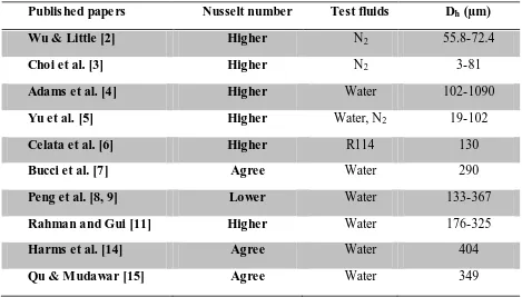
Table 1 summarizes the comparison of fully developed Nusselt number observed by different
researchers with conventional theory. The results clearly show deviations of heat transfer
predictions as compared to classical theory. As seen in the table, researchers have different
opinions on agreement of heat transfer enhancement for microchannels relative to conventional
sized channels. Most of the studies pred icted higher fully developed Nusselt number for
[image:22.612.72.541.334.601.2]microchannels whereas there exist a few papers with contradicting views.
Table 1: Summary of previous papers on heat transfer
Publis hed pape rs Nusselt number Test fluids Dh (µm)
Wu & Little [2] Higher N2 55.8-72.4
Choi et al. [3] Higher N2 3-81
Adams et al. [4] Higher Water 102-1090
Yu et al. [5] Higher Water, N2 19-102
Celata et al. [6] Higher R114 130
Bucci et al. [7] Agree Water 290
Peng et al. [8, 9] Lower Water 133-367
Rahman and Gui [11] Higher Water 176-325
Harms et al. [14] Agree Water 404
Qu & Mudawar [15] Agree Water 349
2.1.2. Different Thermal Boundary Conditions
Deviations in heat transfer predictions by classical theory have been mainly attributed to
surface roughness, entrance and exit effects, thermal and flow boundary conditions, etc. Lee et
7
entrance effects by numerically simulating microchannels with inlet and exit manifolds.
Applying correct thermal boundary conditions is also very important in determining accurate
heat transfer coefficients. Different thermal boundary conditions generally applied in fluid
domain are: H1 (axially constant wall heat flux and circumferentially constant wall temperature),
H2 (uniform wall heat flux, axially and circumferentially) and T (uniform wall temperature,
axially and circumferentially) [17].
The fully developed Nusselt number for a rectangular channel depends on channel aspect
ratio. Shah and London [17] presented the data for T and H1 boundary conditions for fully
developed laminar flow with one or more walls capable of transferring heat. Based on their
results obtained for T and H1, following correlations were developed to predict the fully
developed Nusselt number as a function of channel aspect ratio (defined as ratio of shorter side
to longer side) for four side heating:
𝑁𝑢𝑇 = 7.541 1 − 2.610𝛼 + 4.970𝛼2− 5.119𝛼3+ 2.702𝛼4− 0.548𝛼5 (Eq. 1)
𝑁𝑢𝐻1= 8.235 1 − 2.0421𝛼 + 3.0853𝛼2− 2.4765𝛼3+ 1.0578𝛼4− 0.1861𝛼5 (Eq. 2)
Tables 2 and 3 show the values for fully developed laminar Nusselt number for T and H1
respectively with different heating wall configurations. The representation of the fully developed
Nusselt is also shown in Figures 1 and 2 for constant temperature (T) and constant heat flux (H1)
boundary condition respectively.
Figures show that case 1 (four-side heating walls) and case 5 (two- adjacent heating walls)
follow symmetric trend for a fully developed Nusselt number due to negligible gravitational
8
longer side. In general, the fully developed Nusselt number values for case 1 and 5 do not have
any dependency on whether the testing is carried out with horizontal or vertical channel
orientation as the surface area getting heated is same in either case. For example, the fully
developed laminar flow Nusselt number value for four-side T and H1 boundary condition is
5.858 and 6.700 respectively as seen in graph and can estimate same heat transfer predictions
irrespective of channel aspect ratio calculated as 0.1 or 10.
Whereas case 2 (three-side heated walls), case 3 (two-opposite heated walls), and case 4
(one-side heated wall) needs to be estimated for the whole range of aspect ratio as the surface
area of the wall being heated changes with increase in aspect ratio. For example, the values of
fully developed Nusselt number in case of three-side H1 or T boundary condition will not be the
same for aspect ratio of 0.1 and 10 because the heated surface area of rectangular microchannels
will change accordingly. This can be clearly seen in Figures 1 and 2.
Using generalized integral transform technique, Aparecido and Cotta [18] analytically solved
for bulk temperature and Nusselt number in thermally developing laminar flow in rectangular
ducts with uniform wall temperature (T) as the boundary condition. Montgomery and Wibulswas
[19] performed numerical analyses of thermally developing flow in rectangular microchannels
flow in microchannels having aspect ratios ranging from 1 to 10 with the H1 thermal boundary
condition with constant wall temperature (T) and constant wall heat flux (H1) as the boundary
9
Table 2: Fully Developed Laminar flow Nusselt number under T boundary condition with different heated wall configurations for rectangular ducts [17]
Aspect ratio, α
NuT
0.0 7.541 7.541 7.541 0 4.861
0.1 5.858 6.095 6.399 0.457 3.823
0.2 4.803 5.195 5.703 0.833 3.330
0.3 4.114 4.579 5.224 1.148 2.996
0.4 3.670 4.153 4.884 1.416 2.768
0.5 3.383 3.842 4.619 1.647 2.613
0.6 3.198 - - - 2.509
0.7 3.083 3.408 4.192 2.023 2.442
0.8 3.014 - - - 2.401
0.9 2.980 - - - 2.381
1.0 2.970 3.018 3.703 2.437 2.375
1.43 3.083 2.734 3.173 2.838 2.442
2.0 3.383 2.602 2.657 3.185 2.613
2.5 3.670 2.603 2.333 3.390 2.768
3.33 4.114 2.703 1.946 3.626 2.996
5.0 4.803 2.982 1.467 3.909 3.330
10.0 5.858 3.590 0.843 4.270 3.823
∞ 7.541 4.861 0 4.861 4.861
10
Table 3: Fully Develope d Laminar flow Nusselt number under H1 boundary condition with different heated wall configurations for rectangular ducts [17]
Aspect ratio, α
NuH1
0.0 8.235 8.235 8.235 0 5.385
0.1 6.700 6.939 7.248 0.538 4.410
0.2 5.704 6.072 6.561 0.964 3.914
0.3 4.969 5.393 5.997 1.312 3.538
0.4 4.457 4.885 5.555 1.604 3.279
0.5 4.111 4.505 5.203 1.854 3.104
0.6 3.884 - - - 2.987
0.7 3.740 3.991 4.662 2.263 2.911
0.8 3.655 - - - 2.866
0.9 3.612 - - - 2.843
1.0 3.599 3.556 4.094 2.712 2.836
1.43 3.740 3.195 3.508 3.149 2.911
2.0 4.111 3.146 2.947 3.539 3.104
2.5 4.457 3.169 2.598 3.777 3.279
3.33 4.969 3.306 2.182 4.060 3.538
5.0 5.704 3.636 1.664 4.411 3.914
10.0 6.700 4.252 0.975 4.851 4.410
∞ 8.235 5.385 0 5.385 5.385
11
However, there is little information available for the entrance region heat transfer under the
H2 boundary condition. In a recent review article, Kandlikar [21] emphasized the need to
generate entrance region effects for smooth microchannels under H2 boundary condition.
2.2 Previous Work on Surface Roughness Effects
2.2.1. Previous Experimental Work
Effect of surface roughness in minichannels and mic rochannels are gaining interest for
researchers as roughness elements on channel walls can lead to heat transfer enhancement
compared to smooth channels due to combined effects of area enhancement and flow
modification. Nikuradse [22] conducted an extensive experimental study with water in circular
pipes to predict the effect of surface roughness on pressure drop for laminar and turbulent
regions, varying Re from 600 to 106. Kandlikar [23] performed critical review on Nikuradse's [22] experimental data to understand the mechanisms that affect fluid-wall interactions in rough
channels.
For narrow channels, experimental data sometimes misleads as they are strongly influenced
by a number of competing effects such as surface roughness, flow modifications and varying
experimental uncertainties. Nikuradse [22] used sand grains deposition to generate roughness
structures on inner channel walls with diameters from 2.42 cm to 9.92 cm. The results predicted
that surface roughness on channel walls do not have any significance on pressure drop in laminar
flow regime.
Kandlikar [23] in 2005 analyzed the experimental data from Nikuradse's work and found that
the manometers used to calculate pressure drop in their experimental set up were well out of
12
overall uncertainty associated to measure pressure drop was estimated between 3 to 5% in
turbulent region whereas it was expected to be significantly higher in the laminar region.
Kandlikar [23] showed that measurements of channel dimensions, reading accurate flow
parameters, and recognizing experimental uncertainties we re the major problems of researchers
to obtain accurate experimental data in late 80's and 90's.
Wu and Little [24, 25] in 1983 carried out similar experiments by etching glass and silicon in
channels with hydraulic diameters ranging from 45 µm to 83 µm for three different fluids such as
hydrogen, nitrogen and argon. They concluded early transition from laminar to turbulent flow in
micro- miniature J-T refrigerators due to higher friction factors observed compared to
conventional theory. Also, the results showed the same slope of friction factors as presented in
conventional Moody diagram.
Kandlikar et al. [26] characterized the effects of surface roughness on pressure drop in single
phase liquid flow. The experiments were performed for rectangular microcha nnels of wide range
of hydraulic diameters from 325 µm to 1819 µm for air and water as fluids. They showed that
the transition from laminar to turbulent occurred earlier than the one predicted in conventional
theory. Moreover, the relation between critical Reynolds number versus relative roughness (ε/Dh, cf) and friction factor versus constricted flow hydraulic diameter (Dh, cf) was observed. More
recently, Kandlikar et al. [27] in 2006 proposed that as the relative roughness increases in
minichannels and microchannels, the critical Reynolds number decreases.
The enhancement of roughness effects in heat transfer and fluid properties in minichannels
and microchannels led to a new modified Moody diagram using the constricted flow parameters
13
turbulent flow at micro level. Figure 3 below shows a new modified Moody diagram using
constricted flow parameters.
Figure 3: Modified Moody diagram based on constricted flow parameters [26]
Weilin et al. [28] carried out experiments on trapezoidal silicon microchannels to investigate
flow characteristics of water with Dh ranging from 51 to 169 µm. Experimental results indicated
higher pressure gradient and friction factor values as compared to conventional laminar flow
theory which may be due to the effects of surface roughness in microchannels. More recently,
Gamrat et al. [29] presented an experimental and numerical study to predict the influence of
roughness on laminar flow in microchannels. The authors noted that Poiseuille number increases
with relative roughness and is independent of Reynolds number in laminar regime (Re<2000).
Brackbill [30], and Brackbill and Kandlikar [31-33] generated a considerable experimental
14
roughness was fabricated on channel walls with relative roughness ranging from 0 to 24%. The
results predicted early transition to turbulence and showed the use of constricted flow parameters
that would cause the data to collapse on to conventional theory line for laminar flow regime.
Sobhan and Garimella [34] presented a comparative analysis of studies on fluid flow and heat
transfer in microchannels. They concluded that the differences between the flow and heat
transfer in microchannels is quite different from that observed in channels of conventional sizes.
Moreover, in spite of the available information in literature, there is no clear evidence to support
reasons for these trends. The discrepancies in predictions may very well be due to the entrance
region effects, differences in surface roughness elements in different microchannels investigated,
non-uniformity of channel dimensions or due to some errors in measurements and high level of
uncertainty while performing experiments. There arises a clear need to perform systematic
numerical analysis which can consider each parameter influencing fluid flow and heat transfer
properties in microchannels.
It is well known that the effects of entrance region are very useful for designing and
optimizing the microchannel heat sinks and other microfluidic devices. There are many results
provided by different investigators on entrance region effects in microc hannels that are quite
different or even contradictory. Gan and Xu [35] performed experimental study in microchannel
heat sink using water and methanol as working fluids. The results showed to vary from
conventional theory and obtained the percentage of entry length to the whole length of the
channel was up to 12.5 to 56.2%. Barber and Emerson [36, 37] found that the entry length in
microchannels was almost 25% longer than that predicted using continuum flow theory. Zhang et
al. [38] performed numerical analysis in microchannels and predicted that the hydrodynamic
15
2.2.2. Previous Numerical Work
Very few researchers have performed numerical analysis to estimate the effect of surface
roughness by generating random obstructions in channels. Hu et al. [39] developed a numerical
model to simulate rectangular prism rough elements on the surfaces and showed significant
effects of roughness height, spacing and channel height on velocity distribution and pressure
drop.
Croce et al. [40, 41] investigated the effects of roughness elements on heat transfer and
pressure drop in microchannels through a finite element CFD code. As seen in Figure 4, they
modeled roughness elements as a set of random peak heights and different peak arrangements
along the ideal smooth surface. Their results predicted a significant increase in Poiseuille number
as a function of Reynolds number. Moreover, a remarkable effect of surface roughness on
pressure drop was observed as compared to a weaker one on the Nusselt number. Their results
show great dependence of surface roughness effects on fluid flow properties.
16
Rawool et al. [42] in 2006 presented a three-dimensional simulation of flow through
serpentine microchannels with roughness elements in the form of obstructions generated along
the channel walls as shown in Figure 5. They found that the obstruction geometry plays a vital
role in predicting friction factor in microchannels. The effects of friction factor in case of
rectangular and triangular obstructions were more and the value decreased for trapezoidal
roughness element. The numerical results concluded that roughness pitch as an important design
parameter and the value of pressure drop decreases with increase in roughness pitch.
Figure 5: Geometry of trapezoidal roughness element and velocity vector map around obstruction [42]
Kleinstreuer and Koo [43, 44] proposed a new approach to capture relative surface roughness
in terms of a porous medium layer (PML) model. They evaluated the microfluidics variable, i.e.
roughness layer thickness and porosity, uncertainties in measuring hydraulic diameters, and inlet
Reynolds number as a function of PML characteristics.
Stoesser and Nikora [45] numerically investigated the turbulent open-channel flow over 2D
square roughness for two roughness regimes using Large Eddy Simulation (LES). They signified
the effects of roughness height, roughness pitch, and roughness width as the relative
17
After performing an extensive review on previous works, there certainly arises a need to
investigate the effects of fluid flow and heat transfer changes due to roughness elements in
microchannels. In spite of having wide experimental and numerical data for pressure drop in
literature, the flow behavior is still under a lot of discuss ion and remains an unresolved problem.
Therefore, a systematic study is followed using a numerical CFD approach to understand the
effects of flow modifications and area enhancement on transport processes in presence of
structured roughness elements in microchannels. The numerical model used to predict the
hydrodynamic and thermal characteristics in presence of roughness elements on channel walls is
also compared with some of the experimental data obtained by another researcher in the same
18
3.
OBJECTIVES
After an extensive literature review, it became clear that the heat transfer data under H1
boundary condition assumes constant circumferential wall temperature and axial uniform heat
flux which does not exactly represent the applicability at microscale level. However, H2
boundary condition of uniform axial and circumferential heat flux boundary condition makes
more sense and is more logical to use for estimating heat transfer predictions for microchannel
heat exchanger designs. But there is no substantial data available for H2 boundary condition
which can be directly used to predict transport processes in microchannels.
Also, due to short lengths employed in microchannels, entrance header effects can be
significant and needs to be investigated. Moreover, the effects of surface roughness at microscale
level still remains under a lot of discussion and a systematic study needs to be performed to
analyze the fundamental effects of pressure drop and heat transfer coefficient in presence of
roughness. The objective of the current work is to focus on two main unresolved issues at
microscale level, to estimate heat transfer rate under H2 boundary conditions and to perform
detailed numerical study to predict the effects of fluid flow and heat transfer in presence of
surface roughness in microchannels.
3.1. Microchannels under H2 Boundary Condition
In the present work, rectangular microchannels with aspect ratio ranging from 0.1 to 10 are
numerically simulated using commercial CFD software FLUENT for const ant wall heat flux H2
(constant axial and circumferential wall heat flux) boundary condition and different heated wall
configurations. The following five different boundary conditions are investigated:
19 (2) uniform heat flux on three walls,
(3) uniform heat flux on two opposing walls,
(4) uniform heat flux on one wall, and
(5) uniform heat flux on two adjacent walls.
Fully developed Nusselt number (NuH2) results of four-wall heating conditions are compared
with the published data of Shah and London [17] for validating the numerical model. In order to
study the effects of entrance conditions on Nusselt number, microchannels having inlet and
outlet headers are studied. Numerical results of this geometry (with headers) are compared with
the results for microchannels of the previous case having abrupt entrance (plain microchannels
with no headers).
In the next step, rectangular microchannels with aspect ratios ranging from 0.1 to 10 are
simulated to generate large data sets for Nusselt number with uniform heat flux H2 boundary
condition, circumferentially and axially at three walls, two opposed walls, one wall and two
adjacent walls. In addition, generalized correlations are developed to fit the numerical results for
predicting the fully developed Nusselt numbers for rectangular microchannels with different
heated wall configurations under H2 boundary condition.
3.2. Influence of Surface Roughness in Microchannels
The surface roughness has been acknowledged to affect the laminar flow, and this feature is
the focus of the current work to evaluate its potential in heat transfer enhancement. A numerical
model used for predicting heat transfer under H2 boundary condition for smooth rectangular
channel is extended to accurately analyze the thermal and hydrodynamic characteristics of
20
elements following a sinusoidal pattern are generated on two opposed rectangular channel walls
with a variable gap.
A detailed study is performed to check the effects of roughness height, roughness pitch, and
channel separation on pressure drop and heat transfer coefficient in the presence of structured
roughness elements. This systematic study on structured roughness elements in microchannels
can be extensively used for design, optimization and estimation of transport characteristics in the
21
4.
UNIFORM HEAT FLUX (H2) BOUNDARY CONDITON
FORMULATION
This chapter describes in detail about the mathematical formulation used to generate datasets
for rectangular microchannels under H2 boundary condition. It explains the formulation used for
different wall heating configurations and equations used to predict heat transfer coefficient for
each case. The second part of the chapter mainly focuses on the roughness parameters and
discusses about the influence of constricted flow parameters used for formulating the effects of
surface roughness on friction factor and heat transfer.
4.1. Mathematical Formulation for Rectangular Microchannels unde r H2 Boundary
Condition
The continuity and flow energy equations in their steady state, with associated H2 boundary
conditions for all the cases are solved using finite- volume approach under following
assumptions:
(1) Laminar steady state flow behavior,
(2) Incompressible fluid flow conditions,
(3) Fluid properties remain constant along the length of microchannel,
(4) Neglect viscous dissipation,
(5) Neglect radiative effects.
Table 4 shows the geometric dimensions of rectangular microchannels used for numerical
simulations with varying aspect ratios of 0.1 to 10. The length (l) and height (a) of rectangular
22
with change in aspect ratios as shown in Table 4. Figure 6 represents the cross-sectional area of
rectangular microchannel with constant heat flux boundary condition on all the four walls.
Table 4: Channel dimensions used for numerical simulations for each cases of rectangular microchannel with varying aspect ratios of 0.1 to 10
The aspect ratio and hydraulic diameter for all the different boundary conditions of rectangular
microchannels are defined by Equation (3) below;
Figure 6: Cross-sectional area of rectangular microchannel with uniform heat flux (H2 boundary condition) on all the four walls.
α (a/b)
a (µm)
b (µm)
l (mm)
Dh
(µm)
0.10 150 1500 100 272.73
0.25 150 600 100 240.00
0.33 150 450 100 225.06
0.50 150 300 100 200.00
0.60 150 250 100 187.50
0.75 150 200 100 171.43
1 150 150 100 150.00
2 150 75 100 100.00
5 150 30 100 50.00
23
𝛼 =
𝑎𝑏
and
𝐷
=
4∙𝑎∙𝑏2∙(𝑎+𝑏) (Eq. 3)
For numerical simulations of the case with uniform heat flux on three walls of
microchannels, wall 1 in Figure 6 is kept adiabatic. Similarly, for the two opposed walls and one
wall heating boundary conditions, walls 3 & 4, and walls 2, 3 & 4 are assumed adiabatic walls
respectively. Moreover, for the two adjacent wall heat flux H2 boundary condition, walls 2 and 3
are given constant heat flux circumferentially and axially, whereas walls 1 and 4 are kept
adiabatic.
A finite volume approach is employed to investigate the thermally developing flow regime in
microchannels. The local and average Nusselt numbers are calculated numerically as a function
of non-dimensional axial distance and channel aspect ratio. The heat transfer coefficient and
Nusselt number for rectangular microchannels can be calculated using;
=
𝑞′′𝑇𝑤 ,𝑎𝑣𝑔−𝑇𝑓 ,𝑎𝑣𝑔
and
𝑁𝑢
𝐻2=
𝐷𝑘𝑓
(𝑥)
(Eq. 4)
In Equation (4), the fluid average temperature along the length of microchannel is calculated
using the energy balance equation as follows
𝑇
𝑓,𝑥=
𝑞′′∙𝑃𝑒𝑎𝑡𝑒𝑑 𝑤𝑎𝑙𝑙𝑠 ∙𝑥𝑚∙𝐶𝑝
+ 𝑇
𝑓,𝑖𝑛 (Eq. 5)The temperature distribution around the rectangular channel walls is not uniform under H2
boundary condition. The temperature is the highest at the corners of the wall whereas it is the
lowest at the center-line on the walls subjected to H2 boundary condition. Representations of
24
ratio of 0.5 (width - 300 µm and height - 150 µm) is shown in figures 7, 8, and 9. It can be seen
that the wall temperature is not constant circumferentially along the rectangular channel.
Therefore, heat transfer estimation depends upon the location of wall temperature measured
along the circumference. Figure 8 and 9 shows a variation of temperature along the width of 300
µm and height of 150 µm respectively in a fully developed region. In order to estimate heat
transfer coefficient accurately, several points are taken along the temperature profile and an
average wall temperature is estimated.
Figure 7: Cross-sectional area of rectangular microchannel with H2 boundary condition on 4-walls for 0.5 aspect ratio (channel width - 300 µm, channel height - 150 µm)
Figure 8: Temperature variation along the width of a rectangular microchannel of 0.5 aspect ratio
315 316 317 318 319 320
0 0.05 0.1 0.15 0.2 0.25 0.3
Te
m
p
e
ra
tu
re
(K
)
Along the width of microchannel (mm)
Twall along the width
T wall 150 µm
25
Figure 9: Temperature variation along the height of a rectangular microchannel of 0.5 aspect ratio
The average wall temperature, obtained from the computational results, is calculated using
temperature at different nodes on each heated walls along the length of the microchannel.
Initially, several points are computed along the heated walls to estimate average wall
temperature. Thereafter, to simplify the calculations, five nodes are selected on the heated wall,
which would able to predict the average wall temperature with maximum error of 0.06%.
Figure 10 below represents the five-node method used to average the wall temperature
profile for wall 1. Similarly, using the five nodes on the wall the average temperature is
determined for each heated wall. 315 316 317 318 319 320
0 0.025 0.05 0.075 0.1 0.125 0.15
Te
m
p
e
ra
tu
re
(K
)
Along the height of microchannel (mm)
Twall along the height
26
Figure 10: Representation of the five nodes used to average wall temperature profile
As discussed above, for each wall of the rectangular microchannel under constant wall heat
flux, temperature peak is observed at corners and hence the temperature values at each corner
nodes are halved while calculating the average temperature for each wall (as represented by
Equation 6 for wall1):
𝑇
1=
0.5∗𝑇𝑁1 +𝑇𝑁2+𝑇𝑁3+𝑇𝑁4+ 0.5∗𝑇𝑁54 (Eq. 6)
where, subscripts N1, N2, .., N5 represents the different nodes which are used to calculate the
average wall temperature for different heating configurations.
The average wall temperature is defined differently depending upon different wall boundary
conditions:
For four-wall uniform heat flux boundary condition as represented in Figure 6, the
average wall temperature used to estimate heat transfer coefficient in Equation 4 can be
defined as;
𝑇
𝑤 ,𝑎𝑣𝑔=
𝑇𝑎∙𝛼+𝑇𝑏1+𝛼 (Eq. 7)
where,
𝑇
𝑎=
𝑇3+𝑇42 and
𝑇
𝑏=
𝑇1+𝑇227
For three-wall uniform heat flux boundary condition (shown in Figure 11);
Figure 11: Cross-sectional area of rectangular microchannel with three -wall H2 boundary condition
𝑇
𝑤 ,𝑎𝑣𝑔=
𝑇𝑎∙2𝛼+𝑇𝑏1+2𝛼 (Eq. 8)
where,
𝑇
𝑎=
𝑇3+𝑇42 and
𝑇
𝑏= 𝑇
2 For two opposed wall uniform heat flux boundary condition (shown in Figure 12);
Figure 12: Cross-sectional area of rectangular microchannel with two opposite wall H2 boundary condition
𝑇
𝑤 ,𝑎𝑣𝑔=
𝑇1+𝑇22 (Eq. 9)
For one-wall uniform heat flux boundary condition (shown in Figure 13);
28
𝑇
𝑤 ,𝑎𝑣𝑔= 𝑇
1 (Eq. 10) For two adjacent wall uniform heat flux boundary condition (shown in Figure 14);
Figure 14: Cross-sectional area of rectangular microchannel with two adjacent wall H2 boundary condition
𝑇
𝑤 ,𝑎𝑣𝑔=
𝑇2+𝛼𝑇31+𝛼
(Eq. 11)
4.2. Theoretical Conside rations for Structure d Roughness elements
Kandlikar et al. [26] characterized the effects of surface roughness on pressure drop in
single-phase fluid flow. Kandlikar et al. [27] proposed that critical Reynolds number decreases
with increase in relative roughness. Based on the enhancement of roughness effects on transport
behavior in minichannels and microchannels, a new modified Moody diagram was developed
using the constricted flow parameters over the entire range of Reynolds number. The new
Moody diagram as seen in previous section (Figure 3) shows the representation of early
transition from laminar regime to turbulent at micro level, as observed by many researchers.
In representing the roughness effects on microscale, Kandlikar et al.[26] proposed a new set
of roughness parameters shown in Figure 15. Rpmis the maximum height of a roughness element
from the main profile mean line. Sm is defined as the mean separation of profile irregularities,
29
between the floor profile mean line (Fp) and main profile mean line. These values are established
to accurately define the roughness profile of a surface and to contradict the assumption that the
surface roughness can be simply defined by the average roughness, Ra. The roughness height is
the sum of FdRa and Rp. These parameters detail the surface profile in a more in-depth as
compared to Ra.
Figure 15: Schematic diagram of roughness parameters [26]
The derivation of the constricted parameters is useful in accurately calcula ting friction
factor in high roughness channels [30]. This work utilized the constricted parameter scheme of
Kandlikar et al. [26] and Brackbill and Kandlikar [30-33]. In the case of smooth microchannels,
a channel has a cross-section of height „a‟ and width „b‟. Whereas, for a channel with surface
roughness on the two opposite walls of a rectangular microchannel, the parameter acf represents
the constricted channel height. Figure 16 shows a generic representation of the constricted
geometric parameters.
30
In order to recalculate the constricted parameters, acf and Acf can be defined as follows:
𝑎
𝑐𝑓= 𝑎 − 2𝜀
(Eq. 12)𝐴 = 𝑏 ∙ 𝑎
(Eq. 13)𝐴
𝑐𝑓= 𝑏 ∙ 𝑎
𝑐𝑓 (Eq. 14)Constricted perimeter for rough channels is obtained by substituting acf instead of channel
separation a used for smooth channels;
𝑃 = 2𝑏 + 2𝑎
(Eq. 15)𝑃
𝑐𝑓= 2𝑏 + 2𝑎
𝑐𝑓 (Eq. 16)Similarly, the definitions of hydraulic diameter and constricted hydraulic diameter are given as
below;
𝐷
=
4∙𝐴2∙(𝑏+𝑎 ) (Eq. 17)
𝐷
𝑐𝑓=
4∙𝐴𝑐𝑓2∙(𝑏+𝑎𝑐𝑓)
(Eq. 18)
Theoretical friction factors are calculated using the constricted parameters. For laminar flows in
rectangular channels, the theoretical frictio n factor is predicted by Kakac et al. [46], by Eq. (19).
In smooth channels, friction factor is obtained by substituting conventional aspect ratio as
defined in Eq. (20). Whereas, in case of microchannels with surface roughness on channel walls,
Eq. (21) is used to define constricted aspect ratio as shown below:
𝑓𝑡𝑒𝑜𝑟𝑦 =24
𝑅𝑒 1 − 1.3553𝛼 + 1.9467𝛼
2− 1.7012𝛼3+ 0.9564𝛼4− 0.2537𝛼5
(Eq. 19)
𝛼 =
𝑎31
𝛼
𝑐𝑓=
𝑎𝑐𝑓𝑏 (Eq. 21)
Relative roughness is defined as the ratio of roughness height to hydraulic diameter of a channel.
Eq. (22) and Eq. (23) defines the relative roughness for smooth and rough channels respectively.
𝑅𝑅 =
𝜀𝐷
(Eq. 22)
𝑅𝑅
𝑐𝑓=
𝜀𝐷 ,𝑐𝑓
(Eq. 23)
Reynolds number and constricted Reynolds number can be calculated as follows:
𝑚 = 𝑉 ∙ 𝜌
(Eq. 24)𝑅𝑒 =
4𝑚𝜇𝑃 (Eq. 25)
𝑅𝑒
𝑐𝑓=
4𝑚𝜇 𝑃𝑐𝑓
(Eq. 26)
The theoretical pressure drop can be calculated using Eq. (27), which is used for validating
the current numerical model for predicting effects of fluid flow in smooth rectangular channels.
Using the constricted flow parameters, Eq. (28) can be used to find the frictio n factor for
channels with surface roughness on channel walls.
The pressure drop data obtained from numerical simulations for rough microchannels will be
compared with Eq. (27). This comparison will validate the usage of current numerical code to
accurately predict the effects of structured roughness elements on fluid flow in minichannels and
microchannels.
𝑓 =
𝑑𝑃𝑑𝑥
𝜌𝐷𝐴2
32
𝑓
𝑐𝑓=
𝑑𝑃𝑑𝑥
𝜌 𝐷 ,𝑐𝑓𝐴𝑐𝑓2
2𝑚 2 (Eq. 28)
Moreover, in case of surface roughness generated on all the four sides of a rectangular
microchannel, all the above equations should be modified to incorporate constricted channel
33
5.
CFD MODEL DESCRIPTION
This chapter generally discusses about the numerical CFD software used for pe rforming
numerical simulations with different heating configurations. First part of this section mainly
describes the geometric models, defining mesh generation and importance of mesh independency
for each case. Also, it includes the matrix of geometries used to investigate the effect of entrance
type on transport phenomena in microchannels. The second part describes the solid modeling and
meshed generation used for rough microchannels. The details about generating structured
sinusoidal roughness elements on rectangular channel walls with varying roughness height,
roughness pitch and other roughness parameters are extensively explained. The test matrix
selected to evaluate the effects of fluid flow and heat transfer in presence of roughness elements
is referred. Moreover, the different boundary conditions and assumptions used to perform
numerical analysis for different geometries are explained in this chapter.
5.1. CFD Model - Smooth Channels
The fluid flow and heat transfer effects in rectangular microchannels with varying aspect
ratio from 0.1 to 10 are investigated using commercial CFD software, FLUENT. GAMBIT is
used as the pre-solver software for designing geometric models, grid generation and defining
boundary walls, inlet and outlet faces. Water enters the rectangular microchannels with a fully
developed velocity profile at an inlet temperature of 300K.
The numerical simulation is initially performed for rectangular microchannels with four-side
constant wall heat flux boundary condition. This case is tested for different aspect ratios of 0.1,
0.25, 0.33, 0.5 and 1, and the results are verified by the scheme proposed by Shah and London
34
heating conditions. Following the validation, data sets under uniform heat flux (H2) boundary
condition for three-walls, two-opposed walls, one-wall and two-adjacent walls are generated for
the whole range of aspect ratios from 0.1 to 10.
The rectangular channels used in Shah and London‟s investigation have abrupt entrance type
as shown in Figure 17. In general, the channel always has some type of headers for practical
applications. Hence, new geometric models are designed with same rectangular microchannel
dimensions as earlier along with a smooth entrance type (with inlet and outlet headers) as shown
in Figure 18. This comparison helps us to understand the effect of entrance types on heat transfer
characteristics in entrance region.
35
Figure 18: Schematic of geometric model with smooth entrance type
As discussed, the pre-solver GAMBIT is used for grid generation in microchannels. Figures
19 and 20 show the meshed geometry of rectangular channel having aspect ratio of 1 with abrupt
entrance type and smooth entrance type respectively. Hexwedge cooper scheme is used for
generating mesh in rectanugular geometries. The mesh spacing is kept as low as possible to
justify the conformity of obtained results. Finer meshes are created to predict the fluid flow and
heat transfer effects more accurately. Each of the rectangular geometries possess approximately
3 million grid elements and the processing time for each simulation is noted to be around 7-8
hours (Intel Core 2 Duo processor). Grid independence test is also carried out in order to ensure
the best mesh spacing for the numerical model.
Further, all the mesh geometries are imported in numerical simulation CFD so ftware,
36
Figure 19: Schematic of meshed model with abrupt entrance type having aspect ratio of 1
37
confirm laminar flow through rectangular microchannels. Pressure-based solver is used to
achieve steady state analysis. The SIMPLE (Semi-Implicit Method for Pressure-Linked
Equations) al
![Table 2: Fully Developed Laminar flow Nusselt number under T boundary condition with different heated wall configurations for rectangular ducts [17]](https://thumb-us.123doks.com/thumbv2/123dok_us/49641.4507/25.612.75.538.103.651/developed-laminar-nusselt-boundary-condition-different-configurations-rectangular.webp)
![Figure 30 (a) Integrated test piece with support block, (b) Original image of sinusoidal roughness elements etched on channel wall, (c) Assemble of test set-up, and (d) Workbench along with the experimental test set-up assembly [47]](https://thumb-us.123doks.com/thumbv2/123dok_us/49641.4507/65.612.92.540.64.642/integrated-original-sinusoidal-roughness-assemble-workbench-experimental-assembly.webp)