A novel method of 3D motion object’s position perception
Tan Wei1, a, Xuan Liu2 and Chen Yi1, Erfu Yang3
1 School of Computer and Network Security, Dongguan University of Technology, 523808 Dongguan, China 2 School of Economics and Management, Dongguan University of Technology, 523808 Dongguan, China
3Department of Design, Manufacture and Engineering Management University of Strathclyde, Glasgow G1 1XJ,UK
Abstract. With the development of industrial automation, location measurement of 3D objects is becoming
more and more important, especially as it can provide necessary positional parameters for the manipulator to grasp the object accurately. In view of the disabled object which is in widespread use currently, its image is captured to obtain positional parameters and transmitted to manipulators in industry. The above process is delayed, affecting the work efficiency of the manipulator. A method for calculating the position information of target object in motion is proposed. This method uses monocular vision technology to track 3D moving objects,then uses contour sorting method to extract the minimum constrained contour rectangle, and combines the video alignment technology to realize the tracking. Thus, the measurement error is reduced. The experimental results and analysis show that the adopted measurement method is effective.
1 Introduction
Automatic robotic systems have more and more been desirable for many real-world applications such as automatic surveillance, vehicle control and industrial robot. Vision sensors provide a wide range of information for both motionless or motion object; they can provide wide role for automatic control of robotic systems.
Machine vision [1] is widely used in manipulator control, defect detection and so on. A large number of relevant studies have emerged [2-6]. In the industrial world, there are many application scenarios in which objects are conveyed by automatic conveyor belts. In order to improve production efficiency, robots are often used for picking and handling. Since the target object needs to be perceived to start the robot to grab it, machine vision provides a good technical means for manipulators. At present, there are many studies on manipulators, which use machine vision to obtain and analyse images, and then control the trajectory of the robot by the obtained position parameters [3-7]. However, at present, many robots use the target object in the stationary state to sense the position information of the object [3]. Although this method is simple, it is unfavourable to the work efficiency of the robot and is lagged behind the operation of the manipulator. At present, there are some studies on the collection, calculation and manipulator control of the target moving objects [7], but they are often not targeted for regular objects. In addition, with respect to camera calibration, Literature [8] proposed a global calibration method that includes the hand-eye pose estimation, Literature [9] proposed a trial calibration technique based on a 2D picture test with a pose estimation algorithm to correct initial difference in AHRS Inertial reference frames and improve joint angle accuracy. In Literature
Aimed at above existing problems, this study focus on position of motion 3D target object, taking the target object of the geometrical shape on the conveyer belt as a research scene.
2 Camera model in OpenCV calibration
method
In the camera calibration, the camera model should be firstly determined. The camera model of OpenCV is based on the ideal pinhole model, and the radial distortion and tangential distortion are introduced. Five coordinate systems are defined in the model: World coordinate system Ow − X Y Zw w w 、 Camera coordinate system
c c c c
O − X Y Z 、Ideal image coordinate system O1 − X Yu u、
Actual image coordinate system O1 − X Yd d 、Image
pixel coordinate system O −UV 。The transformation from the world coordinate system to the image pixel coordinate system is as follows:
(1)The world coordinate system is numbered as a camera sitting system(transformation of the rigid body position in 3D space)
0 1 1 1 c w c w c w X X Y Y Z Z = R T
(1)
Where,
11 12 13
21 22 23
31 32 33
r
r
r
r
r
r
r
r
r
=
R
indicates the rotation matrix;x y z
t
t
t
=
T
indicates the translation matrix.(2)Transformation of the camera coordinate system into the ideal image coordinate system (projective transformation)
0 0 0
0 0 0
0 0 1 0 1 1 c u c u c X X f Y Y f Z = = c
Z (2)
(3)Transformation of ideal Image coordinate system to actual Image coordinate system(distortion considered)
Lens distortion is mainly caused by radial distortion, the lens model of secondary radial distortion is:
2 2 2 2 2
1( ) 2( )
d u u u u u u
X = X + X K X +Y + K X +Y
2 2 2 2 2
1( ) 2( )
d u u u u u u
Y =Y +Y K X +Y + K X +Y
The singular coordinate is expressed as:
1 1 d u d u X X Y Y = '
A (3)
Where
K
1 andK
2 indicate radial distortion coefficients; 'A
indicates equivalent transformation matrix.(4)Transformation of actual image coordinates to pixel image coordinates
n x d d
U
=
U
+
S X
+
γ
Y
0 y d
V
=
V
+
S Y
The homogeneous coordinates is expressed as:
0
0 0
1 0 0 1 1
x d
y d
S U X
U
V S V Y
γ = (4)
Where, ( U V0,0 ) indicates image centre O1 ’s coordinates inO −UV ;Sx,Syeach indicates the number of pixels in the unit distance on the plane of the image in the direction of the axis X and Y;
γ
is the tilting factor between the two coordinate axes.It’s given by formula(1)~(4):
0
0
0 0 0
0 0 0 0
1 0 0 1 0 0 1 0
x
c y
S U
U f
Z V S V f
γ = ' A 0 1 1 1 w w w w w w X X Y Y Z Z = 1 2 R T
M M (5)
WhereM1is determined byS S U V f k kx, y, , , , ,0 0 1 2, relating only to the nature of the camera itself,and these parameters are internal parameters of the camera;M2 is determined by rotation matrix
R
and translation vectorT
, and it’s the external parameter of the camera. At this point, the pixels in the image are reconstructed into three-dimensional points.3 Three-dimensional moving objects
position perception method
Target position and posture perception is composed of 4 parts: image acquisition and preprocessing, calibration, target tracking, video correction, and the process is shown as follows.
Step1.Get the number of corner points and the length and height of the board.
Step2.Load board pictures.
Step3.Find out the chessboard corner and save the corner information to the matrix.
Step4.Determine whether the loading image ends? Yes, go to the next step, or go to Step2.
Step6.Get video from the camera.
Step7.Capture a frame, determine whether the capture was successful, yes, turn to the next step, otherwise it is over.
Step8.Update image, draw rectangular logo. Step9.Get pose information.
Step10.Display the original image and show the corrected image.
Step11.Release the camera. Step12.End.
3.1 Calibration
[image:3.595.318.537.121.262.2]There is a one-to-one correspondence between the coordinate of a certain point in space and the coordinate of the imaging point corresponding to the point in a camera image. The geometric correspondence is determined by the imaging geometry of the camera. The calculation process of camera geometric parameters is called camera calibration. According to different calibration methods, the camera calibration is divided into the following three categories [17]: the traditional camera calibration method, the camera calibration method based on active vision and the camera self-calibration method.
Fig. 1. Calibration plate image grayscale and painted corner Implementation steps:
1, First, select the origin of the world coordinate system, choose the calibration plate at the top left corner of the system as the origin.
2, Make calibration plate and measure board data on the box.
3, Establish two structures, input the same corner pixel coordinates and three-dimensional coordinates respectively.
4, Load the preprocessed image and draw the corner. 5, Introduce the structure as a parameter into the function cvCalibrateCamera2 (), as well as internal and external parameters.
6, Save the calculation results in the xml file.
As is shown in Figure 1, to achieve the effect of this part as an intermediate process, the implementation is fully automated.
After system start, the camera opens, and the qualified picture is taken out from the display window, and the preprocessing module is handed over to the calibration function. The results will be saved into the xml file to correct and obtain the object three-dimensional information needed to extract parameters from the xml file to add the calculation, and the coordinates will be stored in the xml file. As shown in Figure 2.
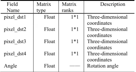
With the design of the pose table storage system of four three-dimensional coordinates and rotation angle of the target object, the storage elements are pixel_dst1, pixel_dst2, pixel_dst3, pixel_dst4 and angle. Table 1 shows the following content:
Pixel_dst1, pixel_dst2, pixel_dst3, pixel_dst4 are the coordinate values of the four corner points of the tracked object and are stored in matrix form in the xml file for the robot to grab when picking up the object.
pickup Display in window Image acqusition
Video update and
correction calibration
Image preprocessing
Xml file Target tracking picture
internal and external parameters
internal and external
parameters internal and external parameters gray image picture
[image:3.595.310.539.308.430.2]Fig. 2. System data flow diagram
[image:3.595.140.216.350.424.2]Angle is the rotation angle of the object, which is the focus of the pose information. Only by knowing the angle of deflection can the robot grasp it accurately.
Table 1. Pose information table Field
Name Matrix type Matrix ranks Description pixel_dst1 Float 1*1 Three-dimensional
coordinates pixel_dst2 Float 1*1 Three-dimensional
coordinates pixel_dst3 Float 1*1 Three-dimensional
coordinates pixel_dst4 Float 1*1 Three-dimensional
coordinates Angle Float —— Rotation angle
The calibration table is used to store the calibration results. The calibration storage table has three fields: internal parameters, external parameters, and homography matrices.
Internal parameters: Intrinsic matrix and focal length parameters
f
x ,f
y (where focal length is in pixels) to model the possible offset of the optical axis, parametersχ
c
andc
y .External Parameters: Distortion coefficient-a vector of size 4 x 1 or 1 x 4 with deformation parameters [k1, k2, p1, p2].
Homomorphism matrix: Homography is a 3 × 3 or 4 × 4 conversion matrix.
x
f
,f
y And the relation between the physical focal length F is:f
x= Fsx andf
y= Fsy. Where sx represents the pixel value of 1 mm length in the x direction, that is, the unit pixel per millisecond, and sy represents the y direction.χ
χ c
Z X fx
reen = ( )+ sc
, y Z cy
Y f y
reen = ( )+ sc
x
f
,f
yare calculated as a whole in camera calibration.3.2 Target Tracking
target recognition, we use the background subtraction method [18]. When there are abnormal objects in the monitoring scene, there will be obvious differences between the frames. Subtracting two frames to get the absolute value of the difference in brightness of the two images, and judging whether it is greater than the threshold value to analyse the motion characteristics of the video or image sequence and determine whether there is any object motion in the image sequence. The inter-frame differential image sequence is equivalent to the image sequence in the time-domain high-pass filter. First, the contour of the target is detected to see the track of the target in the field of view. The basic principle of the inter-frame difference method is to subtract the gray value of the pixels corresponding to the two frames before and after the image. If the gray value of the corresponding pixels is small, the scene can be considered as static; if the grayscale changes somewhere in the image area, it can be thought that this is caused by moving objects in the image. By marking these areas and using these marked pixel areas, we can find the position of the moving object in the image [19].
Start
Initialize threshold
preprocess:gray,do difference between frames,binarization
Obtain image matrix
Finding contour and calculate area of the
contour
Image update
end Draw minimal rectangle of
contour
Noise cancellation: median filtering,down
simpling and so on
If(contour>Contour_Max _Area)
Contour is over? Calculate the rectangle
angular point’s coordinates
Y
Y N
Get the timestamp and current frame’s size
N
Fig.3 program flow chart of target tracking
Fig.4 Motion display of the object under the lens window The purpose of target positioning is to obtain the target's three-dimensional coordinates. First of all, the pixel coordinates of the image are corrected, and then the homography matrices are used to rotate and translate them to obtain three-dimensional coordinates.
Target tracking program flow chart is seen in Fig.3. Fig.4 shows the effect of target recognition and tracking: the contour we see is that the system sets a threshold based on the known object size, filters all the contours less than this threshold, and draws the smallest rectangle with the largest contour. In this way, we can see in the vision of the target trajectory and then calculate the location of the target information.
3.3 Pose information acquisition
Capture a frame
Obtain the frame
Update history image
Capture a frame
Release the device
Save image coordinates for
angular pixel
Correct pixel coordinates
cvPerspectiveTransfo rm()
cvSave() to save 3D coordinates to xml
file start
End
N
Y Y
N If(cvWaitKey(10)==’e’)
Scanning is over for 4 Angular point?
Fig.5 Pose information acquisition program flow chart By adding the target tracking profile information and contour information into the new structure, the algorithm can be enabled by sorting. The maximum value is selected and the maximum contour of the sort has angle information we want to find, then the centroid coordinates can be found. The results are saved to the XML file. Pose information acquisition program flow chart is seen in Fig. 5.
3.4 Video correction
In this part, we calibrate the image of camera by calibrating the homology matrix. When shooting a target with a digital camera, a video camera or other digital devices, the camera often has difficulty in obtaining images perpendicular to the ground (or the photographed plane) due to factors such as shooting distance and alike. Thus, the image is distorted and the quality of the image is degraded, and the subsequent image processing is affected.
(a) Before correction (b) After correction Fig.6 Correction effect display
In this case, the distortion mainly includes two kinds of radial distortion and skew distortion. The radial distortion is corrected many times. In practical work, it has also been applied well. The representative methods are: two-step method, the use of control points, the calibration method based on the camera model, the zoom address correction method [20]. The implementation process of this part is as follows, the implementation effect is shown in Figure 6(due to the limited experimental conditions, it will bring some errors in the use of more flat ground as the target station for sports, and the error analysis will be involved in the later).
1, get the frame from the camera 2, correct the distortion image
[image:4.595.329.518.66.243.2] [image:4.595.90.253.337.560.2] [image:4.595.339.508.488.568.2]4 Experiment and analysis
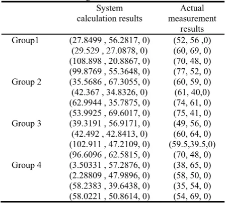
[image:5.595.59.283.182.384.2]The experimental environment is under the operating system of Win 7, using development tools Visual Studio 2013, OpenCV, choosing C++ programming language, using USB camera to obtain calibration images. Four measurements are taken to obtain their respective measurements.
Table 2. System calculation and actual measurement results of angular coordinates
System calculation results
Actual measurement
results Group1 (27.8499 , 56.2817, 0)
(29.529 , 27.0878, 0) (108.898 , 20.8867, 0) (99.8769 , 55.3648, 0)
(52, 56 ,0) (60, 69, 0) (70, 48, 0) (77, 52, 0) Group 2 (35.5686 , 67.3055, 0)
(42.367 , 34.8326, 0) (62.9944 , 35.7875, 0) (53.9925 , 69.6017, 0)
(60, 59, 0) (61, 40,0) (74, 61, 0) (75, 41, 0) Group 3 (39.3191 , 56.9171, 0)
(42.492 , 42.8413, 0) (102.911 , 47.2109, 0) (96.6096 , 62.5815, 0)
(49, 56, 0) (60, 64, 0) (59.5,39.5,0)
(70, 48, 0) Group 4 (3.50331 , 57.2876, 0)
(2.28809 , 47.9896, 0) (58.2383 , 39.6438, 0) (58.0221 , 50.8614, 0)
(38, 65, 0) (58, 50, 0) (35, 54, 0) (54, 69, 0)
Table 3. System calculation and actual measurement results of centroid coordinates
System calculation
results Actual measurement results Group 1 (66.5384,39.9053,0) (64,58,0) Group 2 (72.0842,50.14,0) (65,50,0,) Group 3 (70.3329,52.3877,0) (59,51,0) Group 4 (30.5129,48.9456,0) (46,59,0) unit:cm.
In order to verify the effectiveness of the measurement algorithm, the following comparison test is used to compare the data measured by the algorithm with the actual manual measurement results. Table 2 shows the experimental results.
As we can see from the data in Table 2, there is a certain error in the detection of the diagonal point of the system, so there is certain deviation between the detection value of the corner point and the actual value.
In table 3, the error rates of the X and Y values are calculated respectively:
X: [(64-66.5)/64+(65-72)/65+(59-70)/59+(46-30)/ 46] /4=17.2%
Y: [(58-39)/59+(50-50)/50+(51-52)/51+(46-48)/ 46] /4=9.9%
From the calculation results, the error rate on the x coordinate is relatively large. The error analysis of the experiment is as follows:
1, Number of images: the impact of the calibration method on the camera calibration accuracy requires each image to be shot from a different angle, that is, the image is a field of view and only a homology H matrix is determined. The number of images is H number. In the process of solving the homography matrix of the camera's
internal and external parameters, the number of H also affects the calibration accuracy. In the case of no distortion, the camera has 9 parameters, whereas the homography matrix can only determine 8 degrees of freedom. Therefore, it is necessary to calibrate at least 2 images of different perspectives. In order to obtain a stable numerical result, the number of images collected far exceeds the number of times. If the captured images are not enough, it will obviously bring some errors to the calculation of internal parameters. However, collecting too many images will affect the accuracy of the calibration. On the other hand, it will cause error accumulation and increase the error probability. Therefore, an appropriate number of images must be taken into account. This selection contains 15 calibration images.
2, Re-projection error and noise error: re-projection error increases rapidly with the increase of the noise standard deviation, and the calibration results are very sensitive to the world coordinates. In order to further improve the calibration accuracy, it is necessary to improve the measurement accuracy of planar targets or print accuracy. Theoretically, when the error level is less than 1.5% and the re-projection error is less than one pixel, the error can be controlled within 3 pixels. When the error level is greater than 2%, the projection error increases rapidly.
3, Feature point extraction error: Due to the feature point extraction error, in order to ensure that the internal parameter calibration result is reliable, at most 20 images are needed to make the calibration result stable within 3 pixels.
4, World coordinate measurement error: the generation of calibration plate, often assuming that print black and white checkerboard is equilateral long. However, because the accuracy of the ordinary printer is not high, measurement error is caused by the calibration board. Therefore, it is necessary to study the influence of the measurement accuracy of world coordinates on the calibration.
Based on the analysis of the above error causes, the error factors that we can control are the number of images, the measurement of world coordinates and the relatively good experimental environment. Camera calibration uses up to 15 images to achieve high-precision calibration. In camera calibration, the calibration board is made reasonably, and the number of calibrated images is chosen to calibrate the camera quickly and accurately. These are the shortcomings of our experiments, which lead to greater errors, but the results do not affect our verification of the entire process and its related algorithms, so the method proposed in this article is effective.
5 Conclusion
[image:5.595.59.283.414.494.2]1) Contour sorting method is used to detect the main contour of the three-dimensional moving object, and then calculate the position coordinates of the target object; this method overcomes the shortcoming that the traditional shape objects can only be detected in the past.
2) The experimental error is analysed in detail. In order to improve the accuracy of position sensing, calibration is very important, for it involves the selection of experimental conditions and the number of images. Although we have explored a more general method for measuring the position perception of moving objects of any shape, there are many details that need to be improved and further studied. In the next step, we will enhance our research to improve the accuracy and apply it to the industry.
Acknowledgements
This work was supported by the National Natural Science Foundation of China (Grant no. 61702098), the science and technology planning project of Guangdong P rovince,China(2014A 010103039,2015A010103022, 20 14B090901002 ) , the Dongguan science and technology plan project, Guangdong Province, China(20 14509 102211).
References
1.
Milan Sonka, Vaclav Hlavac, Roger Boyle. Image Processing, Analysis and Machine Vision(the fourthedition) (Beijing :Tsinghua University Press,2016)
2.
Z. Jun. Automatic loading and unloading manipu- lator system based on visual positioning [D]. (Shijiazhuang: Shijiazhuang Railway University, 2012)3.
D. Xi-Chao. Research on Robot-Based Grabbing and Orientation Based on Vision [D] .(Guangzhou: South China University of Technology, 2013)4. X. ZiYue, L. ZhanMing, L. ErChao. Application of OpenCV on Real-time Detection and Processing System of Seam.Computer Technology & Development, page. 39-42,4(2012).
5. L. Shuifa, W. De-xuan, Y. Zhong-fan. Measurement of Inclination between Plane and Inclination Based on Machine Vision. Journal of South China University of Technology: Natural Science.page. 54-59,8( 2011).
6. Alzarok, Hamza; Fletcher, Simon; Longstaff, Andrew P. 3D Visual Tracking of an Articulated Robot in Precision Automated Tasks. Sensors (14248220). Page.1-23,17(2017).
7. G. M, Y. Y, Y. Y, et al. A Positioning System Based on Monocular Vision for Industrial Robots[C]. International Conference on Information Science and Control Engineering. IEEE, page. 784-788(2016). 8. Palmieri, M.-C. Palpacelli, L. Carbonari, et al. Vision
-based kinematic calibration of a small-scale spheri-
cal parallel kinematic machine, Robotics and Comp- uter–Integrated Manufacturing ,page.49 (2018) . 9. Karina Lebela, Mathieu Hamel, Christian Duval,et
al. Camera pose estimation to improve accuracy and reliability of joint angles assessed with attitude and heading reference systems,Gait & Posture,page. 199–205, 59 (2018).
10. DING Yabin, MEI Jiangping, ZHANG Wenchang, et al. Position and Orientation Measurement of Parallel Robot Based on Monocular Vision [J],Journal of Mechanical Engineering, page. 174-179,50(2014). 11. Yang, X & Huang, Y & Gao, F & Han, X. New corner
detection algorithm of chessboard image for camera calibration. Yi Qi Yi Biao Xue Bao/Chinese Journal of Scientific Instrument. Page. 1109-1113,32 (2011). 12. J. Ze, X. Fangzheng, L. Zushu. Space target location measurement based on monocular vision , Transducer and Microsystem Technologies, page. 125-127,131,30(2011).
13. G. F, M. F, Z. Y, Jun W, Sun J, Yang E, Hussain A. Biologically inspired progressive enhancement target detection from heavy cluttered SAR images. Cognitive Computation. Page. 955–966,8 (2016). 14. P. Wang, X. Xiao, Z. Zhang, et al. Study on the
position and orientation measurement method with monocular vision system. Chinese Optics Letters, page. 55-58,8(2010).
15. X. LY. , C. ZQ. , Z. P. et al. A new monocular vision measurement method to estimate 3D positions of objects on floor Int. J. Autom. Comput.Page. 159,14 (2017).
16. NV Ngo, QC Hsu,WL Hsiao , et al. Development of a simple three-dimensional machine-vision measurement system for in-process mechanical parts , Advances in Mechanical Engineering, 9, 10(2017). 17. Hamzah R A, Ghani S F A, Din A, et al. Visualization
of image distortion on camera calibration for stereo vision application[C]. IEEE International Conference on Control System, Computing and Engineering. IEEE, 28-33, (2013).
18. A. Murat Tekalp. Digital video processing . Prentice Hall (1995).
19. QIU D, ZHANG W, GU B, et al. Application of Frame Difference Methods in Real-time Moving Target Tracking. Journal of North China Institute of Water Conservancy and Hydroelectric Power, page. 014,3 (2009).