Abstract: The paper addresses to engineers who do design and optimization work in the field of reciprocating compressors. In this paper theoretical and exact contemplations are given which permit to foresee the valve misfortunes. Suction valve misfortunes are additionally bring about a decrease of limit. The most effective part in the development of a reciprocating compressor depends strongly on improvement of its performance. For this purpose, a performance characteristic evaluation of a two stroke reciprocating air compressor is carried out in this paper. By and large stream misfortunes of compressor valves are affected by the valve geometry as well as are intensified by valve pocket misfortunes. The aims were to improve compressor performance by illustrating the effects of various parameters such as clearance between head and piston, stroke length, friction losses, compressor running time, background working condition and air leakage. The effect of each parameter was compared with given performance condition and after it was demonstrated the most important parameter on the performance. The parameter was measured using three techniques. The experiment addressed some factors that led to the inefficient performance of the reciprocating compressor air system and cause energy losses. The results advocate the optimal time for starting time of starting each stage of the two–stage reciprocating compressor. The work in addition may give a insight for the development of the design of multi-stage compression and presents some key design parameter.
Index Terms: Performance, Volumetric efficiency, compressor valve
I. INTRODUCTION
The compressor valves are the most critical and effective component in a reciprocating compressor, because of their effect on the efficiency (horsepower and capacity) and reliability of the compressor. Compressor valves are devices placed in the cylinder to permit or allow one way flow of gas either in or out of the cylinder. There must be one or more valves for inlet and discharge in each compression chamber (cylinder end). Compressor valves are nothing more than check valves, but they are required to operate reliably for about a billion cycles, with opening and closing times measured in milliseconds, with no leakage in the reverse flow direction and with low pressure loss in the forward flow direction. To make matters worse, they are frequently
Revised Manuscript Received on August 05, 2019
Jayesh Ravindra Patil, Mechanical Department, Vishwakarma Institute of Technology, Pune, India.
Rajkumar Bhagat, Mechanical Department, Vishwakarma Institute of Technology, Pune, India.
expected to operate in highly corrosive, dirty gas, while covered in sticky deposits.
Compressor valves affect performance due to the pressure drop caused by flow through the valve; the leakage through the valve in the reverse direction and the fact that the valves do not close exactly when an considering ideal valve.
Following factors affect both the capacity & power of the compressor,
a) Due to its inertia, the valve does not open instantaneously.
b) Due to the springing, the valve does not stay at full lift for the full time it is open
c) The valve does not close exactly at the dead centre.
Fig.1 Plate Valve
Basically, an automatic compressor valve requires only three components to do the required work:
1. Valve seat 2. Sealing element
3. A stop to contain the travel of the sealing element However, a valve comprising only the above components installed in a modern compressor would not fulfil the expected life and efficiency requirements.
Modern compressor valves either incorporate or exhibit the following:
1. Large passage area of valve and good flow dynamics for low throttling effect (pressure drop)
2. Low mass of the moving parts of valve for low impact energy
3. Quick response to low differential pressure
4. Small outside dimension to allow for low clearance volume
5. Low noise level 6. High reliability factor and long life.
Optimization of Clearance Volume for
Performance Improvement of Reciprocating
Compressor
7. Ease of maintaining and servicing
II. PROBLEMSTATEMENT
Optimization and improvement in performance of Reciprocating Compressor is critical part of compressor design to maintain or decrease in pressure loss, decrease the power loss, decrease the weight, make a compact design and manufacturing point of view.
Excess clearance, wrong valve lift, excess weight and over design of compressor components cause the following effects on compressor.
• Increases pressure losses
• Increases velocity
• Decrease in Volumetric Efficiency
• Decrease in FAD
• Increase in Power
III. OBJECTIVE
1. Literature survey to study performance of Reciprocating Compressor and compressor valves 2. To study effect of clearance volume on Efficiency
and FAD
3. Evaluate various performing parameter a) Volumetric Efficiency b) Free Air Delivery
c) Pressure loss d) Velocity of air
4. Finite Element Analysis carried out for design Cylinder as per ASME Section VIII Div 2- Design By Analysis Requirement
5. Design calculation for optimized valve lift and weight reduction
6. Modify given Cylinder and Valve as per results
IV. LITRTUREREVIEW
Optimization of connecting rod was proposed by
Pravardhan S. Shenoy and Ali Fatemi [1] explain to decrease weight and assembling cost of a produced steel interfacing pole exposed to cyclic burden including the pinnacle compressive gas load and the pinnacle dynamic ductile burden at 5700 rev/min, relating to 360o wrench edge. The basic variables considered for weight decrease during the streamlining procedure included weakness quality, static quality, clasping opposition, twisting firmness, and pivotal solidness. Extra imperatives forced during the streamlining procedure included keeping up the manufacture capacity just as compatibility of the enhanced interfacing bar with the current one.
Cost was diminished by changing the material of the current produced steel associating bar to crackable fashioned steel (C-70). The procedure of break part wipes out the need to independently manufacture the top and the body of the interfacing bar or the need to saw or machine a one piece produced associating bar into two. Warmth treatment, machining of the mating appearances of the wrench end, and boring for the sleeve are likewise wiped out.
Moon Kyu Lee [2] was introduced aprocedure of estimating critical buckling stress for a connecting rod was suggested by using FEA with actual loading and boundary conditions. The
validity of the buckling analysis was demonstrated by analyzing the sensitivity in yield,
fatigue and buckling, which are important guides for weight reduction design of connecting rod shank.Critical buckling of rod, complicated shape gradients and actual boundary conditions cannot be reflected in the conventional formula. Thus exact elastic buckling stress must be calculated by FEA with the real shape and boundary conditions. The critical plastic stress is taken as the increased yield strength by work hardening during rod forging.
The connecting rod analysis was carried out by Mohammed Mohsin Ali H [3] to check the fatigue life and alternating stress development due to service and assembly loads with variation in load distribution. In this paper he does 3D model of connecting rod Catia and Axi-symmetric analysis is carried out to find interference effect on the stress behavior in the joint. 8 nodded plane82 element with quadratic displacement variation is used for accurate results. The contact pair is created with Targe169 and Contac172 elements. Interference is created through geometric built up .he conclude that contact pressure development at the interface and higher compressive stress in the bush and tensile stress development in the small end. The results are plotted for radial, hoop and von-misses stresses. Also a three dimensional views are obtained through Ansys axisymmetric options.
Mark Perkovich
[4] portrays trial testing of an open-drive
twin-chamber responding refrigeration blower having spring-stacked ring-type valves, and an examination of anticipated execution to test results is finished with the assistance of a PC reproduction. The chamber weight, and movements of the release and suction valves will be accounted for. The refrigerant utilized was R-12, despite the fact that the outcomes could be by implication connected to different refrigerants, specifically for approval of PC models. At the same time trial estimations were set aside a few minutes, at every level of crankshaft turn. Estimations were taken at relentless state condition. Despite the fact that there were contrasts between the two during the suction and release forms, The trial and anticipated chamber weights concurred great, which can be credited to impacts which were not represented in the PC model. Static conduct of the valves, for example, when the valve opens, was anticipated great. In any case, forecast of the dynamic movement of the valves by the PC model was not by any stretch of the imagination exact demonstrating that refinements are fundamental in the displaying of the valve elements.Adolf Burgstaller [5] demonstrates that impelled valve is regularly utilized in the admission complex of little hermetically fixed responding blowers. During the gas trade process the because of the throttling procedure valve misfortunes impact the general execution by which the weight drop is expanded between the admission port and the gas assembly of such a machine. So there is an addition in the gas trade work individually the cylinder work to have the comparative release weight. In 2 different ways these valve misfortunes impact the COP. To start with, in the expansion of the utilization of electrical
lessening of the mass stream rate. In view of this planner needs to comprehend the dynamic conduct of such a valve. In this paper, numerical and exploratory examinations are done to evaluate the impact of principle parameters of the suction valve on the general execution of the blower. Utilizing the AVL BOOST, a CFD programming program the thermodynamic cycle count is performed. Entire blower space between shell channel and outlet is secured by figuring model. Utilizing an equal spring-damper mass framework, dynamic valve removal is determined. The investigations are affected on a calorimetric test seat.
Aditya Bhakta [6] demonstrates the work straightforwardly relates valve elements to the blower vitality productivity. Past investigations lessening weight misfortunes because of valve geometry, towards improved blower execution is increasingly engaged. All encompassing valve advancement system is finished by breaking down the valve 'shudder' prompts a. Generally, weight incited reed valves is utilized in responding hermetic blowers on the suction and release ports. A normal for these valve task during a solitary suction and release beat they have the numerous opening and shutting movements. This is progressively significant for the suction reed thinking about the more extended (wrench point) term of the suction procedure. In the present work, the reed valve elements has been changed over to rearranged single level of opportunity spring mass framework and is caught by a scientific model inside a 15% precision go for dislodging expectation. Thinking about the present phase of advancement, this is inside adequate breaking points. In-blower valve lift estimations (direct strain check estimations) in a shut circle refrigeration apparatus have been utilized to approve this model, in-blower valve lift estimations (direct strain check estimations) in a shut circle refrigeration apparatus have been utilized. As multifaceted nature and time included is considered with the in-blower estimations, a rearranged system to describe the elements of reed valves outside the blower (roundabout estimations) has additionally been proposed and created. Since the premise of this investigation is examining the trademark valve elements, material science based exchange capacities can make an interpretation of these estimations to the genuine blower reed movement prompting a quicker plan cycle. Likewise To give a nitty gritty knowledge to the stream material science, CFD has been utilized. With the majority of the above data sources, utilizing scientific models distinguishing key plan parameters and assess calculated structures towards a perfect/picked valve reaction.
Gustavo C. Rezende [7clarified spillage through valves can essentially decrease the volumetric and isentropic efficiencies of blowers. In spite of its significance in blower structure, the dimensional portrayal of spillage holes is certainly not a minor errand. In this paper, creator built up a joined trial numerical technique to assess the spillage hole of blower valves. By means of constatnt volume technique estimations of spillage were done, which is generally utilized in the investigation of gas course through small scale channels. Furthermore with a one-dimensional stream model, forecasts were gotten, considering thick contact, slip at the dividers, and gas compressibility. To coordinate the expectation of estimations of spillage for various weight contrasts the spillage hole was balanced in the reenactment
model. For the investigation of three valve structures of refrigeration blowers same technique was connected.
R. E. Drews [8] demonstrates that consistent want to limit machine vacation while getting crest execution of the hardware is the target of each producer and end client. One part of responding blowers Which has a characterize influence on both of these is the blower valve. The creator surveys the advancement program of a responding blower valve that conveys a more drawn out normal life proportion alongside an expansion in the valves stream coefficient.
V. METHODOLOGY
Fig.2 Methodology
VI. MATHEMATICALCALCULATIONS
A. For piston displacement,
Pd=[π/4xD2xSxRPM]+[π/4(D2
-d2)xSxRPM] Pd=16.89 m3/min
B. For volumetric efficiency,
ηv=[LF-(%clearance/100)x{(P2/P1)(1/ᵞ)-1}]x100
ηv=80.58%
C. For free air delivery,
FAD= [Piston displacement x Volumetric efficiency]/100 FAD= 13.61 m3/min
1. Lame’s Equation
t = 9.84 mm
2. Chlumsky Equation
t = 10.52 mm
E. Valve lift calculation,
h = 1.4 mm
F. Pressure drop
Pf = 0.028 bar
G. Power loss
P1= 619.59 W
Total valve loss is 2.2%
Table 1. Material Properties
Parameter Value Unit Notation
Tensile Strength 300 Mpa Sut
Young’s Modulus 1.28E5 Mpa E
Density 7250 Kg/mm
3
ρ
[image:4.595.48.278.48.556.2]Allowable stress for FG 300 Material= 67.5 Mpa
Fig 2. 3D model of cylinder VII. POSTPROSESINGRESULTS
[image:4.595.320.524.114.364.2]A. Cylinder 1. Meshing
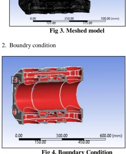
Fig 3. Meshed model
[image:4.595.305.517.414.582.2]2. Boundry condition
Fig 4. Boundary Condition
For cylinder boundary conditions are at one end it is fixed and at inside the cylinder there is air pressure and at outside in water jacket there is water pressure
3. Post process Results
Fig 5. Postprocess Results
The maximum deformation comes at the water inspection plate 0.12 mm due to water pressure.
The maximum principle stress comes out 40.21 Mpa which is less than allowable stress 67.5 Mpa.
Therefore design is safe.
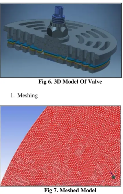
[image:4.595.57.279.547.680.2]Fig 6. 3D Model Of Valve
[image:5.595.305.547.49.221.2]1. Meshing
Fig 7. Meshed Model
For valve the element size is 0.3 mm due to its small clearance or gap for passing of air.
[image:5.595.308.546.301.670.2]2. Boundary condition
Fig 8. Boundary Condition
For valve inlet we put velocity of air while entering the valve and at valve outlet we put velocity of air while laving the valve.
1. Postprocess results
Fig 8. Postprocess results
From the results and above figure bar 1 shows analyticle calculated velocity of air is 19.36 m/s
From the results and above figure bar 2 shows the FEA calculated velocity of air is 19.2 m/s
VIII. RESULTS
1) Volumetric efficiency:
2) Free air delivery (FAD)
[image:5.595.46.294.439.609.2]4) Power loss in valve
5) Velocity difference in valve
6) Pressure difference
IX. CONCLUSION
The results observed during this analysis are within range with similar available existing results and governing
standards. The following points can be concluded from the results observed during this study.
1. Due to optimization of clearance volume volumetric efficiency increased by 1.79 %
2. Due to optimization of clearance volume FAD increased by 1.92 %
3. Due to optimizing the thickness of cylinder the weight of cylinder reduced by 7.73 % 4. Due to optimized valve lift velocity reduced by
11.16%
5. Due to optimized valve lift power loss reduced by 0.16 kilowatts
6. Pressure is increased by 4.76%
ACKNOWLEDGMENT
I am very pleased to present the paper on “Development of Balanced Opposed Piston Reciprocating Compressor for Performance Improvement”. I would like to mention a special thanks to my respected project guide Prof. R.K. Bhagat Sir, who have given ongoing and enormous assistance at the individual level.
I would also like to thank Mr. Hitendra Patil for providing support for this study on reciprocating compressor. They have provided continual guidance to assist in preparing and completing the paper on schedule.
I am very happy to have worked under my project guide Prof. R.K.Bhagat
REFERENCES
1. Pravardhan S. Shenoy and Ali Fatemi,”Connecting Rod Optimization for Weight and Cost Reduction”, The University of Toledo, SAE International, 2005.
2. Moon Kyu Lee, Hyungyil Lee, Tae Soo Lee & Hoon Jang,” Buckling sensitivity of a connecting rod to the shank sectional area reduction”, Department of Mechanical Engineering, Sogang University, Seoul 121-742, Republic of Korea, Materials and Design 31 (2010) 2796–2803.
3. Mohammed Mohsin Ali H & Mohamed Haneef,” Analysis of Fatigue Stresses on Connecting Rod Subjected to Concentrated Loads At The Big End”, Dept of Mechanical Engineering, Ghousia College of Engineering, Ramanagaram-562159, Karnataka, VTU, Belgaum, Proceedings 2 ( 2015 ) 2094 – 2103.
4. Perkovich, M.; Kuehn, T. H.; and Ramsey, J. W., "Experimental Testing and Computer Simulation of a Reciprocating Refrigeration Compressor" (1994). International Compressor Engineering Conference. Paper 1010. 5. Burgstaller, Adolf; Nagy, Daniel; Almbauer, Raimund; and Lang,
Wolfgang, "Influence of the Main Parameters of the Suction Valve onthe Overall Performance of a Small Hermetic Reciprocating Compressor" (2008). International Compressor Engineering Conference.
6. Bhakta, Aditya; Dhar, Sandeep; Bahadur, Vaibhav; Angadi, Shruti; and Dey, Subhrajit, "A Valve Design Methodology For Improved Reciprocating Compressor Performance" (2012). International Compressor Engineering Conference. Paper 2077.
7. Rezende, Gustavo C.; Silva, Ernane; and Deschamps, Cesar J., "A Combined Experimental-Numerical Procedure to Estimate LeakageGap of Compressor Valves" (2016). International Compressor Engineering Conference. Paper 2442.
AUTHORSPROFILE
Jayesh Patil, M.Tech Mechanical Design Engineering,
Vishwakarma Institute of Technology, Pune Maharashtra, INDIA – 411037
Rajkumar Bhagat,
Professor, Mechanical Engineering Vishwakarma Institute of Technology, Pune Maharashtra, INDIA - 411037