Numerical simulation of environmentally-safe
technologies in power engineering
Alexei Trinchenko1*
1 Peter the Great St. Petersburg Polytechnic University, Institute of power Engineering and Transpor-tation Systems, 195251 Polytechnicheskaya st. 29, Russian Federation
Abstract. One of the effective tools of solving engineering problems is the mathematical simulation of newly built and reconstructed industrial equipment. A necessity of solving identical problems fully belongs to ge-nerating equipment of thermal power plants too, which makes the use of methods of mathematic simulation quite a promising one in the course of designing power-generating units. The work presents the results of simula-tion and subsequent incorporasimula-tion of the method of low-temperature vortex fossil solid-fuel combustion. Based on the developed algorithms and calcu-lation program the assessment of environmental indicators of reconstructed boiler equipment has been carried out and compliance with environmental standards with respect to the level of emissions of gaseous pollutants into environment confirmed. The incorporation of the method being considered into power-generating production has made it possible to reduce emissions of gaseous nitrogen oxides during combustion of coals of different types by 30%.
1 Introduction
The incorporation of big heat-and-power units into power industry, sophistication of process diagrams and operating conditions, increasing requirements to economical efficiency, reliability and environmental indicators thereof will be accompanied by the necessity of building numerical models and conducting simulation studies. It is impossible to carry out such investigations within a short period of time without using modern computers and methods of mathematic simulation [1, 2]. The numerical models make it possible to view an object on a real scale, change geometry of the plant, fuel characteristics, orientation of action of burner jets and parameters thereof, promptly make assessment of effect of performed changes on the efficiency of operation of power-generating equipment and its environmental indicators in a relatively short time [3].
There appeared a possibility to include into viewing the ever-growing determining factors and assess the influence thereof on the intensity of pollutants generation and on the burning process as a whole as much as the computer equipment gets developed. The methods of mathematic simulation, models and programs for expert calculations of processes in the furnace are more and more widely used in the process of building the new boiler equipment in world practice in the most recent decades, which help assess the
efficiency of influence of different technical and mode-related factors, which reduces the labor content and increases reliability of substantiating technical solutions significantly. Such an approach is especially required in the process of development of new technologies of combustion and optimization of burning processes.
The low-temperature vortex (LTV) method of burning developed under the guidance of Professor V. V. Pomerantsev [4] has proven itself presently to be one of the up-to-date and advanced methods for incorporation into power industry. The use of LTV method helps significantly reduce the emissions of pollutants into atmosphere, increase efficiency of using energy resources, increase reliability and economic efficiency of electric power installations [5, 6]. The LTV burning opens great opportunities for decreasing overall dimensions of boilers and reducing metal expenditures as a result of increasing intensity of combustion and heat-exchange processes. The application of LTV technology makes it possible to install new boilers into existing building boxes, and in some cases – increase the capacity of an installation [7]. It is especially important when replacing the worn-out Central Heating and Power Plant equipment (in the course of upgrading thereof).
The purpose of this work consists in the development of model of low-temperature vortex burning process for increasing environmental indices of boilers and incorporation of LTV method in power industry.
2 Principles of organization and simulation of low-temperature
vortex method
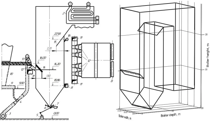
The mathematic description of investigation object (Fig. 1) has been obtained in the way of building a three-dimensional model on the basis of coordinates of characteristic points restricting a furnace of the low-temperature vortex boiler and reflecting the incorporated design solutions (Fig. 2). The model gives a chance of changing geometry of the burners, furnace and its individual assemblies for optimizing design characteristics of mode-related parameters of boiler operation.
Fig. 1. Boiler with low-temperature vortex burning
[image:2.482.63.424.402.610.2]low-efficiency of influence of different technical and mode-related factors, which reduces the labor content and increases reliability of substantiating technical solutions significantly. Such an approach is especially required in the process of development of new technologies of combustion and optimization of burning processes.
The low-temperature vortex (LTV) method of burning developed under the guidance of Professor V. V. Pomerantsev [4] has proven itself presently to be one of the up-to-date and advanced methods for incorporation into power industry. The use of LTV method helps significantly reduce the emissions of pollutants into atmosphere, increase efficiency of using energy resources, increase reliability and economic efficiency of electric power installations [5, 6]. The LTV burning opens great opportunities for decreasing overall dimensions of boilers and reducing metal expenditures as a result of increasing intensity of combustion and heat-exchange processes. The application of LTV technology makes it possible to install new boilers into existing building boxes, and in some cases – increase the capacity of an installation [7]. It is especially important when replacing the worn-out Central Heating and Power Plant equipment (in the course of upgrading thereof).
The purpose of this work consists in the development of model of low-temperature vortex burning process for increasing environmental indices of boilers and incorporation of LTV method in power industry.
2 Principles of organization and simulation of low-temperature
vortex method
The mathematic description of investigation object (Fig. 1) has been obtained in the way of building a three-dimensional model on the basis of coordinates of characteristic points restricting a furnace of the low-temperature vortex boiler and reflecting the incorporated design solutions (Fig. 2). The model gives a chance of changing geometry of the burners, furnace and its individual assemblies for optimizing design characteristics of mode-related parameters of boiler operation.
Fig. 1. Boiler with low-temperature vortex burning
technology Fig. 2temperature vortex burning technology . Model of boiler with
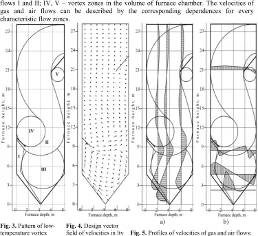
[image:3.482.57.432.116.459.2]low-The implementation of LTV method is based on building special aerodynamics of moving flows provided by the furnace chamber design, which includes individual areas (Fig. 3): I – hot air flow arriving at the furnace from beneath (downdraft (DD) jet), II – flow arriving at the furnace via burners; III – vortex area of furnace formed during interaction of flows I and II; IV, V – vortex zones in the volume of furnace chamber. The velocities of gas and air flows can be described by the corresponding dependences for every characteristic flow zones.
Fig. 3. Pattern of low-temperature vortex burning organization
Fig. 4. Design vector field of velocities in ltv furnace chamber
а) b)
Fig. 5. Profiles of velocities of gas and air flows:
а) by furnace height; b) by furnace depth
The profile of external portion of semi-restricted downdraft jet (zone I) will be described by the dependence according to the theory of Prandtl-Schlichting, as follows:
3 2
21 ( ) ( ext )
ext m W m W m
w W W Y Y Y Y , (1)
while the internal portion of downdraft jet will be described by the dependence, as follows:
2.3
0 ,5
1 0.5 ( ) ( )
int m W m W m W m
w W W Y Y Y Y (2)
The path of jet axis (zone II) is described according to [8] by the equation for the system of jets in the cross-flow:
2.5 2
c c c
2
0 0 0 0 0 0
(273 / ) 1.9
(273 / )
T W
a y a x a x
ctg
b T W b b
where, а – coefficient characterizing the jet structure, its initial turbulence and non-uniformity of field of velocities at the nozzle outlet (with a uniform field at nozzle outlet а = 0.10...0.12); 0 and с– densities of jet and cross-flow, accordingly; W0 and Wc– initial velocities of jet and cross-flow; b0– nozzle width; х – distance from nozzle exit section along jet axis; – angle of attack.
Zones III, IV and V are described by the model of quasi-solid body:
(R)= const, (4)
where, angular velocity, R distance to vortex zone center.
Describing velocities of gas and air flows by the dependencies (1)...(4) for characteristic regions grants a chance to get the vector field of velocities (Fig. 4) and use it for calculating the paths of motion of burning fuel particles of variable mass. The model makes it possible to get the vector of velocity in any point of furnace chamber (Fig. 5), and close the balance of flow rates in the cross sections along coordinate axes.
3 Model of low-temperature vortex burning process and
generation of gaseous nitrogen oxides
An investigation of generation of toxic nitrogen oxides (NO) in case of operation on Cheremkhovo black coal, Azeiskoye and Irsha-Borodinskoye brown coals has been performed by means of numerical simulation with the use of developed fuel burning model taking into account the renowned NO generation mechanisms [9], and decomposition of nitrogen oxides to carbon particles in the process of multiple circulation. Combustion theory takes into consideration occurrence of process in stages for the particles of natural solid fuel and makes it possible to study its separate stages: drying, ignition and burning of volatile matter, burning of coke carbon as well as includes blocks of calculation of screening characteristics, field of temperatures, furnace aerodynamics, motion and destruction of reacting particles of polifraction fuel, generation of nitrogen oxides and decomposition thereof on coke surface.
The model of burning in LTV furnace involves a theory of "reduced film" offered by V.V. Pomerantsev and S.M. Shestakov [8]. Burning of big coke particles of high-moisture fuel is described by the set (5) of chemical reactions (thermal effect in kJ/mole) taking into account reaction No.5 – decomposition of nitrogen oxides on the surface of burning fuel particles:
2 2 2 2
2
heterogeneous
at "dry" gasification at "w et" gasification
1. C + O = CO + 394.6 3 . C + H O = CO + H 130.4 2. 2C + O = 2CO + 219.6
2 2 2
2 2 4
2 2 2 2
3 . C + 2H O = CO + 2H 132 3. C + CO =2CO 175.6 3 . C + 2H = CH 4.8 , hom ogeneous
4. CO + O =2CO + 570.2 4 . 2H + O = H 7
2
2
4 2 2 2
2 2 2
O + 231.5 4 . CH + 2O = CO + 2H O + 891 4 . CO + H O = CO + H + 40.4
(5)
where, а – coefficient characterizing the jet structure, its initial turbulence and non-uniformity of field of velocities at the nozzle outlet (with a uniform field at nozzle outlet а = 0.10...0.12); 0 and с– densities of jet and cross-flow, accordingly; W0 and Wc– initial velocities of jet and cross-flow; b0 – nozzle width; х – distance from nozzle exit section along jet axis; – angle of attack.
Zones III, IV and V are described by the model of quasi-solid body:
(R)= const, (4)
where, angular velocity, R distance to vortex zone center.
Describing velocities of gas and air flows by the dependencies (1)...(4) for characteristic regions grants a chance to get the vector field of velocities (Fig. 4) and use it for calculating the paths of motion of burning fuel particles of variable mass. The model makes it possible to get the vector of velocity in any point of furnace chamber (Fig. 5), and close the balance of flow rates in the cross sections along coordinate axes.
3 Model of low-temperature vortex burning process and
generation of gaseous nitrogen oxides
An investigation of generation of toxic nitrogen oxides (NO) in case of operation on Cheremkhovo black coal, Azeiskoye and Irsha-Borodinskoye brown coals has been performed by means of numerical simulation with the use of developed fuel burning model taking into account the renowned NO generation mechanisms [9], and decomposition of nitrogen oxides to carbon particles in the process of multiple circulation. Combustion theory takes into consideration occurrence of process in stages for the particles of natural solid fuel and makes it possible to study its separate stages: drying, ignition and burning of volatile matter, burning of coke carbon as well as includes blocks of calculation of screening characteristics, field of temperatures, furnace aerodynamics, motion and destruction of reacting particles of polifraction fuel, generation of nitrogen oxides and decomposition thereof on coke surface.
The model of burning in LTV furnace involves a theory of "reduced film" offered by V.V. Pomerantsev and S.M. Shestakov [8]. Burning of big coke particles of high-moisture fuel is described by the set (5) of chemical reactions (thermal effect in kJ/mole) taking into account reaction No.5 – decomposition of nitrogen oxides on the surface of burning fuel particles:
2 2 2 2
2
heterogeneous
at "dry" gasification at "w et" gasification
1. C + O = CO + 394.6 3 . C + H O = CO + H 130.4 2. 2C + O = 2CO + 219.6
2 2 2
2 2 4
2 2 2 2
3 . C + 2H O = CO + 2H 132 3. C + CO =2CO 175.6 3 . C + 2H = CH 4.8 , hom ogeneous
4. CO + O =2CO + 570.2 4 . 2H + O = H 7 2 2
4 2 2 2
2 2 2
O + 231.5 4 . CH + 2O = CO + 2H O + 891 4 . CO + H O = CO + H + 40.4 (5)
5. 2NO + C = N2 + CO – 180.2. (6)
The consideration of burning process from the diffusion-kinetic positions has made it possible to compile a system of non-linear differential equations of diffusion and kinetics of the following type:
2
j i
j 2 ; j ( j j0); i i
D
d p dG
D
dG dx G p p C k
RT dx RT d
, (7)
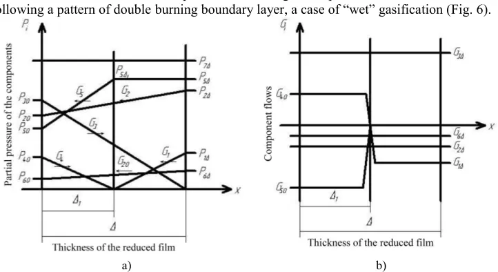
taking into account oxidation and reduction reactions taking pace on the surface of particles, and homogeneous reactions taking place within the limits of boundary layer. The calculations have shown that the process of burning takes place in the intermediate area following a pattern of double burning boundary layer, a case of “wet” gasification (Fig. 6).
[image:5.482.64.425.179.376.2]а) b)
Fig. 6. Distributions of Partial Pressures (а), and Flows of Components (b) in Shown Film for Case of
“Double Burning” Boundary Layer, “Wet Gasification”:
1 –О2; 2 –СО2; 3 –СО; 4 –Н2; 5 –Н2О; 6 – NO; 7 – N2. Indices “0” – Particle Surface; “” – Flow As a result of solving a system of equations (7) an expression has been obtained for carbon flow burning out from the surface of particle, (kmole/(m2s)):
'
2 2 2
'
3 3 5
0
3 3 5
0.5 ,
1 1 1
D
c CO O H NO
N
N N
G p p p p
RT N N N
(8)
and dependences for calculating loss of mass and particle dimensions:
r 2 2
W vol c C C
C C C
C 2
, kg/s; , kg/(m s); , m/s ,
dm
dm dm dm dm G M d M G
d d d d d d
(9)
where, Mс = 12 kg/kmole – molar mass of carbon; m = /63eq – mass of spherical particle, kg; fsurf = 2eq – area of external surface, m2.
The distribution of NO concentrations across furnace cross section (after concentrations) in the known field of gas flow velocities has been determined in the way of numerical solution (diagram “against flow” [10]) of differential equation of mass exchange, in case of presence of source term (zones of NO generation):
2
NO NO NO NO NO
( C ) ( wC ) D C J ,
where, СNO– mass concentration of nitrogen oxides; w– gas flow velocity; DNO– average effective coefficient of NO diffusion in the mixture of furnace gas; JNO – intensity of generation of nitrogen oxides (power of NO source [11]):
2 2
2
2 i i 01 _ N 1 _ N i i i
NO 1,8
i i 02 _ NO 2 _ NO i i 2 i i
N ( ( )) (1 ) N
.
N O ( ( )) (1 ) O N
d d k exp E RT T
J
d d k exp E RT T
(11)
The amount of nitrogen oxides decomposed on the surface of burning carbon particles is calculated proceeding from the balance of reaction No.5.
The motion of reacting particles has been described by Meshchersky equation:
1
( )
k
i fl i
dV dm
m P W V
d d
. (12)
The calculations of paths of particles motion in the known field of velocities have been conducted in the way of numerical solution of equation (12) taking into account influence of two major forces: force of aerodynamic resistance and gravity force recorded in projection at the axis of rectangular coordinate system:
2 2 2
x
x x x x y y z z
y 2 2 2
y y x x y y z z
2 2 2
z
z z x x y y z z
( ) ( ) ( )
2
( ) ( ) ( )
2
( ) ( ) ( )
2 g
g
g
cf dV
m W V W V W V W V
d
dV cf
m W V W V W V W V
d cf dV
m W V W V W V W V mg
d
. (13)
As Re ≤ 1: с = 24/Re; as Re > 1: с = 24/Re+4/Re1/3; as Re > 1000: с = 0.48. In this case the particles of fuel of irregular shape have been replaced with the spherical ones equivalent by volume:
36 /
eq abc
. (14)
The consumption of natural solid fuel of polifraction composition has been recalculated to equivalent consumption of spherical particles. The size of fuel particles, the quantity thereof per 1 kg of designed fuel, mass within the limits of every fraction and area of the initial surface of response have been determined in the way of processing the screening curve. The distribution of particles by fractions has been described by Rosin-Rammler-Bennet formula:
R0i = exp(-bn
0i), (15)
where, b and n– are experimental coefficients [8].
Thus, the burning out of polifraction composition fuel is calculated with the use of equivalent consumption as the sequence of calculations of burning out single particles, where every particle corresponds to one of fuel fractions. At that it is assumed that particles in the process of moving interact with screen heating surfaces only restricting the furnace chamber.
where, СNO– mass concentration of nitrogen oxides; w– gas flow velocity; DNO– average effective coefficient of NO diffusion in the mixture of furnace gas; JNO – intensity of generation of nitrogen oxides (power of NO source [11]):
2 2
2
2 i i 01 _ N 1 _ N i i i
NO 1,8
i i 02 _ NO 2 _ NO i i 2 i i
N ( ( )) (1 ) N
.
N O ( ( )) (1 ) O N
d d k exp E RT T
J
d d k exp E RT T
(11)
The amount of nitrogen oxides decomposed on the surface of burning carbon particles is calculated proceeding from the balance of reaction No.5.
The motion of reacting particles has been described by Meshchersky equation:
1 ( ) k i fl i dV dm
m P W V
d d
. (12)
The calculations of paths of particles motion in the known field of velocities have been conducted in the way of numerical solution of equation (12) taking into account influence of two major forces: force of aerodynamic resistance and gravity force recorded in projection at the axis of rectangular coordinate system:
2 2 2
x
x x x x y y z z
y 2 2 2
y y x x y y z z
2 2 2
z
z z x x y y z z
( ) ( ) ( ) 2 ( ) ( ) ( ) 2 ( ) ( ) ( ) 2 g g g cf dV
m W V W V W V W V
d
dV cf
m W V W V W V W V
d cf dV
m W V W V W V W V mg
d
. (13)
As Re ≤ 1: с = 24/Re; as Re > 1: с = 24/Re+4/Re1/3; as Re > 1000: с = 0.48. In this case the particles of fuel of irregular shape have been replaced with the spherical ones equivalent by volume:
36 /
eq abc
. (14)
The consumption of natural solid fuel of polifraction composition has been recalculated to equivalent consumption of spherical particles. The size of fuel particles, the quantity thereof per 1 kg of designed fuel, mass within the limits of every fraction and area of the initial surface of response have been determined in the way of processing the screening curve. The distribution of particles by fractions has been described by Rosin-Rammler-Bennet formula:
R0i = exp(-bn
0i), (15)
where, b and n– are experimental coefficients [8].
Thus, the burning out of polifraction composition fuel is calculated with the use of equivalent consumption as the sequence of calculations of burning out single particles, where every particle corresponds to one of fuel fractions. At that it is assumed that particles in the process of moving interact with screen heating surfaces only restricting the furnace chamber.
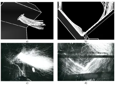
The comparison of calculation and experimental paths of particles movement in LTV furnace has demonstrated close agreement thereof (Fig. 7).
а) b)
[image:7.482.60.437.63.340.2]c) d)
Fig. 7. Comparison of calculation and experimental paths of particles movement in LTV furnace of boiler БКЗ-210-140ф: а), b) – Calculation paths of particles; c), d) – Experimental paths of particles (visualization of flows by means of burning sawdust moistened in kerosene; а), c) – Development of burner jet in initial area; b), d) – Movement in bottom vortex zone of LTV furnace
The distribution of temperatures in LTV furnace has been determined by the zonal heat calculation in he way of numerical solution of balance equations recorded for every of eight zones (two by depth and four by height) of the furnace.
More accurate two-component scheme recommended for utilization during analysis of process of thermolysis of fuel rich in volatile matter has been used in the developed model for calculating volatile matter yield. The constant values of the rate of decomposition reac-tions shown in [8] have been used during calculation.
4 Results of numerical investigation of burning process,
analysis of generation and transformation of nitrogen oxides
The results of calculation according to the presented model have been shown by the example of Azeiskoye brown coal.
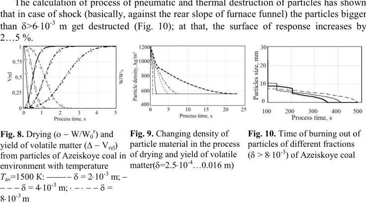
The comparison of calculation curves of volatile matter yield from a particle measuring
The calculation of process of pneumatic and thermal destruction of particles has shown that in case of shock (basically, against the rear slope of furnace funnel) the particles bigger than >610-3 m get destructed (Fig. 10); at that, the surface of response increases by
2…5 %.
Fig. 8. Drying ( W/W0r) and
yield of volatile matter ( Vrel)
from particles of Azeiskoye coal in environment with temperature
Тav=1500 К: = 210-3 m;
= 410-3 m; =
810-3 m
[image:8.482.57.425.72.284.2]Fig. 9. Changing density of particle material in the process of drying and yield of volatile matter(=2.510-4…0.016 m)
Fig. 10. Time of burning out of particles of different fractions ( > 810-3) of Azeiskoye coal
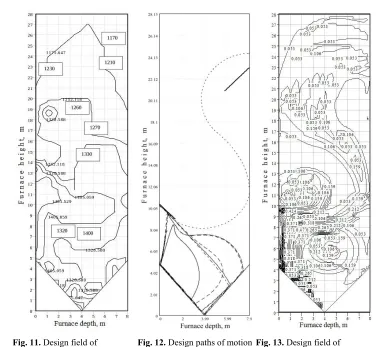
The design field of temperatures in LTV furnace for determining constant values of speeds of chemical reactions is shown in Fig. 11.
The analysis of paths of particles movement has shown (Fig. 12) that coarse particles (>60010-6 m) get accumulated at the front slope of the bottom vortex zone forming a zone of high near-wall concentrations of fuel and coke particles. The main emission of NO takes place in this zone (Fig. 13) – an area of maximum NO concentrations. A vertical area over burners can be also attributed thereto. The burning of coarse particles continues up to a moment, when effected by the downdraft jet they can be carried to a straight-flow portion of the flame.
The maximum amount of NO gets decomposed at the front slope of the bottom vortex zone, since maximum concentrations of nitrogen oxides are available in this area, while the big fuel particles dwell for the maximum period of time of the entire combustion process.
Due to decomposition of nitrogen oxides on coke particles in calculating the process of burning of crushed Azeiskoye deposit coal, the reduction of NO concentration in the smoke gas equals 28 % (NO"т = 500 mg/nm3); burning time – 383 s, value of mechanical underburning q4=1.4 %.
In case of burning of coarse dust of Azeiskoye deposit brown coal (R90=80 %, R200=50 %) small fuel particles (≤60010-6 m) coming into fuel chamber immediately go to straight-flow flame portion, while the big ones (>60010-6 m) turning at the rear furnace wall come to the bottom vortex zone. The zone of maximum NO decomposition on the coke particles is arranged in the bottom vortex zone, NO decomposition equals 15% of the initial emission; time of particles burning– 10 s. The maximum amount of nitrogen oxides decomposition is accounted for by the particles 10=95910-6 m, which is explained by rather significant time of oxides presence in the bottom vortex zone. Therefore, the coarsening of particle-size distribution of the burnt fuel (within the limits down to the particles of crushed fuel), will contribute to the increased NO decomposition.
The calculation of process of pneumatic and thermal destruction of particles has shown that in case of shock (basically, against the rear slope of furnace funnel) the particles bigger than >610-3 m get destructed (Fig. 10); at that, the surface of response increases by
2…5 %.
Fig. 8. Drying ( W/W0r) and
yield of volatile matter ( Vrel)
from particles of Azeiskoye coal in environment with temperature
Тav=1500 К: = 210-3 m;
= 410-3 m; =
810-3 m
Fig. 9. Changing density of particle material in the process of drying and yield of volatile matter(=2.510-4…0.016 m)
Fig. 10. Time of burning out of particles of different fractions ( > 810-3) of Azeiskoye coal
The design field of temperatures in LTV furnace for determining constant values of speeds of chemical reactions is shown in Fig. 11.
The analysis of paths of particles movement has shown (Fig. 12) that coarse particles (>60010-6 m) get accumulated at the front slope of the bottom vortex zone forming a zone of high near-wall concentrations of fuel and coke particles. The main emission of NO takes place in this zone (Fig. 13) – an area of maximum NO concentrations. A vertical area over burners can be also attributed thereto. The burning of coarse particles continues up to a moment, when effected by the downdraft jet they can be carried to a straight-flow portion of the flame.
The maximum amount of NO gets decomposed at the front slope of the bottom vortex zone, since maximum concentrations of nitrogen oxides are available in this area, while the big fuel particles dwell for the maximum period of time of the entire combustion process.
Due to decomposition of nitrogen oxides on coke particles in calculating the process of burning of crushed Azeiskoye deposit coal, the reduction of NO concentration in the smoke gas equals 28 % (NO"т = 500 mg/nm3); burning time – 383 s, value of mechanical underburning q4=1.4 %.
In case of burning of coarse dust of Azeiskoye deposit brown coal (R90=80 %, R200=50 %) small fuel particles (≤60010-6 m) coming into fuel chamber immediately go to straight-flow flame portion, while the big ones (>60010-6 m) turning at the rear furnace wall come to the bottom vortex zone. The zone of maximum NO decomposition on the coke particles is arranged in the bottom vortex zone, NO decomposition equals 15% of the initial emission; time of particles burning– 10 s. The maximum amount of nitrogen oxides decomposition is accounted for by the particles 10=95910-6 m, which is explained by rather significant time of oxides presence in the bottom vortex zone. Therefore, the coarsening of particle-size distribution of the burnt fuel (within the limits down to the particles of crushed fuel), will contribute to the increased NO decomposition.
[image:9.482.50.440.58.405.2]In case of combustion of fine-grained pulverized brown coal (R90=50 %, R200=0.2 %) of Azeiskoye deposit, the burning of all particles takes place in the straight-flow flame portion (analog of straight-flow pulverized coal flame), Fig. 12. The maximum concentrations of generated nitrogen oxides are located at the level of burners, while the zones of NO maximum decomposition are located further in the direction of flame travel. During 1.5 s of burning NO decomposition has amounted to 0.58% of the initial emission.
Fig. 11. Design field of temperatures (К) in LTV furnace (experimental values are shown in boxes)
Fig. 12. Design paths of motion of burning particles in boiler LTV furnace:
– - –=210-6 m;
=0.016 m
Fig. 13. Design field of concentrations of nitrogen oxides
[image:9.482.62.424.533.652.2](by volume, %) in case of burning fuel in LTV furnace The calculations of burning and decomposition of nitrogen oxides for Irsha-Borodinskoye brown coal and Cheremkhovo black coal are made in a similar way. The calculation results are shown in Table 1.
Table 1. Results of calculated analysis of influence of particle-size distribution on decomposition of nitrogen oxides in the course of burning of Irsha-Borodinskoye brown coal and Cheremkhovo
black coal
Fuel
Irsha-Borodinskoye brown coal
Ar=6 %, Wr=33 %,
Сr=43.7 %, Nr=0.6%; Qr
i=15.67 МJ/kg
Cheremkhovo black coal Ar=27 %, Wr=13 %,
Сr=45.6%, Nr=0.7%, Qr
i=17.89 МJ/kg
Particle-size
distribu-tion crushed fuel coarse dust fine dust crushed fuel coarse dust fine dust NO decomposition in
Reduction of NO
emissions, % 31 12 0.6 25 6.6 0.54
According to acquired calculation results the value of nitrogen oxides decomposition (as compared with initial emission) is within the limits: in case of crushed fuel burning of
20…31 %; in case of coarse dust burning of 5…15 %; in case of fine dust burning of 0.5…0.7 %, and depends on fuel composition (first of all, composition of nitrogen and carbon in as-received basis) and kinetic constant values of system reactions (5). Thus, the coarsening of fuel grind burnt in the low-temperature vortex furnace contributes to the reduction of emissions of gaseous nitrogen oxides, reduction of plant explosion hazard as well as reduces electric power expenditures for fuel grinding.
5 Conclusive provisions and findings
The algorithm and program of calculation of process of burning of organic fuel in the low-temperature vortex furnace have been developed on the basis of presented model. The use of model has made it possible to authentically predict emissions of gaseous nitrogen oxides in case of reconstruction to the low-temperature vortex method of boilers of low (БКЗ-75 Southern thermal plant of Rubtsovsk town) [12], medium (БКЗ-210 of Kirovskaya CHPP-4 and БКЗ-220 of Novomoskovskaya regional hydro-electric power plant (RHEPP) [13–20] and high (П-49 Nazarovskaya RHEPP) [21, 22] capacity. The acquired calculation data have been used as the basis for environmental substantiation of reconstruction projects and proven a possibility of fulfilling applicable standards for the level of emissions of nitrogen oxides to environment in case of burning of a wide range of fuels: peat, brown and black coals of different grades.
As a result of incorporation of low-temperature vortex burning in the foregoing boilers a significant reduction (up to 30 %) of emissions of nitrogen oxides to atmosphere has been attained proving by the same high efficiency of this method, while LTV technology can be referred to as a promising method of reducing ecological burden on the environment.
References
1. А. Rodionov, ECM in aerodynamics (1985)
2. V. Antonov, Mathematics. Mathematic models of thermal power-engineering processes (2008)
3. E. Volkov, L. Zaichik, V. Pershukov, Simulation of solid fuel burning (Nauka, Mos-cow, 1994)
4. Y. Rundygin, K. Grigoriev, V. Skuditsky, Low-temperature swirl technology of burn-ing: experience of implementation, perspective of use (Publishing house Politekh, St. Petersburg, 2006)
5. K. Grigoriev, V. Skuditsky, Y. Rundygin, A. Trinchenko, Swirling-type furnace. Eura-sian patent of 008691 (2007)
6. K. Grigoriev, V. Skuditsky, Y. Rundygin, A. Trinchenko, Swirling-type furnace. Pat-ent of 2253801 Russia. Publ. 10.06.2005. Bulletin No 16 (2005)
7. K. Grigoryev, Y. Roundyguine, V. Skuditskii, R. Anoshin, A. Paramonov, A. Trin-chenko, Proceedings of the 7th International Symposium on Coal Combustion (2012) 8. V. Pomerantsev, K. Arefyev, D. Akhmedov, S. Shestakov, Bases of the practical
the-ory of burning (Energoatomizdat, Leningrad, 1986)
9. V. Kotler, Nitrogen oxides in combustion gases of boilers (Energoatomizdat, Moscow, 1987)
10. M. Patankar, Numerical methods of problem solving of heat exchange and fluid dynam-ics (1984)
11. V. Babiy, Burning of coal dust and calculation of coal-dust torch (1986) 12. A. Trinchenko, A. Paramonov, IOP Conf. Ser.: Earth Environ. Sci., 90 (2017) 13. V. Osmanov, SPbPU J. of Eng. Sci. and Tec., 4 (183) (2013)
14. A. Trinchenko, A. Paramonov, SPbPU J. of Eng. Sci. and Tec., 23_(02) (2017) 15. A. Trinchenko, A. Paramonov, Advances in Intelligent Systems and Computing,692
(2017)
16. K. Grigoriev, V. Skuditsky, Y. Zykin, Power Tech. and Eng., 4 (2010) 17. K. Grigoriev, V. Skuditsky, R. Anoshin, Energetik, 1 (2009)
18. A. Paramonov, M. Kadyrov, A. Trinchenko, Procedia Engineering, 206 (2017) 19. A. Paramonov, M. Kadyrov, A. Trinchenko, Procedia Engineering, 206 (2017) 20. V. Osmanov, Improving heat measurements on the basis of heat flow gradient
trans-mitters (Saint Petersburg Polytechnic University, Saint Petersburg, 2015)
21. A. Trinchenko, A. Paramonov, V. Skouditskiy, R. Anoshin, J. Phys.: Conf. Ser.,891
(2017)