Abstract: In small and medium enterprise industry the usage of automation machine is not entirely applied in this sector. This is because of the initial cost to setup automation machine is higher than employed a worker to do the task. The main problem by using human workforce is worker need to do the repetitive task every single day. Human incline to start boring also the productivity of the worker is decreasing. By producing this portable Mini CNC Machine, the problem can be solved. This machine is going through the design development process from data comparison to product fabrication. The detailed design development process ensures that the final result of the machine is achieving the objective to reduce and eliminate repetitive task perform by human resources. The machine control by the new concept of the controller with an open-source controller that makes the machine more flexible and easier to handle. The machine is tested the machining tolerance to ensure the machine provides high accuracy result. Although, the machine still limited to perform the heavy-duty process, this machine can help small and medium enterprise industry increasing productivity by eliminating and reducing human error.
Keywords:Arduino, portable mini CNC machine.
I. INTRODUCTION
Modular design of Semi-Automated Computer Numerical Control (CNC) machine have similar mechanical system concept to the usual CNC machine. The difference between this machine with the usual industry machine is the size of this machine is much smaller and portable compared to the usual industry CNC machine but have limited machining area. This machine design to provide the different type of simple operation that needs precision movement also help to do repetitive work in small operation that needs manpower. Mini CNC machine or can be called as Do It Yourself (DIY) CNC machine is not a new technology, but each machine only has a specific operation that gives limit process can be done. This machine is designed and fabricates to operate a different type of process by changing the tool and coding of the operation. This machine has a gantry arm can hold a different type of tool that can operate a different type of operation. It can perform a
Revised Manuscript Received on October 05, 2019. * Correspondence Author
Johan Ihsan Mahmood*, Mechanical Section, Universiti Kuala Lumpur Malaysian Spanish Institute, Kulim Hi-Tech Park, 09000, Kulim, Kedah, Malaysia.
Muhamad Safwan Hilmi, Student, Bachelor of Engineering Technology in Mechanical Design, Universiti Kuala Lumpur Malaysian Spanish Institute. Kulim Hi-Tech Park, 09000, Kulim, Kedah, Malaysia.
Pranesh Krishnan, Intelligent Automotive Systems Research Cluster, Electrical Electronic and Automation Section, Universiti Kuala Lumpur Malaysian Spanish Institute, Kulim Hi-Tech Park, 09000, Kulim, Kedah.
decoration process for cake in the culinary industry to the precision operation like screwing in the electrical part.
Companies nowadays keep improving their products to provide minimum reject product that can affect production cost by rework and scrap. This problem occurs because of many factors, and one of them is a simple and repetitive task. For a big company, they can increase the quantity of the worker or provide an automation machine to improve the productivity and minimum the repetitive task to a single worker. Besides, for a small and medium company that only have a small quantity of worker and existing automation machine will increase the production cost for them. By increasing the quantity of worker, the labor cost also will increase. All this problem affects the total cost of the production operation.
A Multipurpose Semi-Automated Computer Numerical Control (CNC) machine is designed. that can perform different operations for the small and medium industry. The kinematics and dynamics performance of the mechanical system of the Multipurpose Semi-Automated Computer Numerical Control (CNC) machine is analyzed. A practical design also the mechanical system for the machine is fabricated.
This project will be focusing on the optimizing the existing Mini CNC machine for better usage for small and medium industry operation only. The study is focusing on a repetitive task and precision task. This study is to optimize the usage of the Mini CNC machine to execute more than one operation for a single machine. By applying more than one operation in a single machine the machine capable of solving the problem faced by small and medium enterprise industry.
II. LITERATURE REVIEW
A. Mini CNC machine
A mini CNC machine is the small CNC machine that can function the same as another CNC machine. The difference is only the size of the part can operate, and the operation can be conducted by this machine. This machine usually can be divided into two groups, which are turning machines and milling machine. Currently, only these two operations are converted into a mini CNC machine. A turning machine comprises a workpiece rotating at high speed, and the tool is moved back and forth and in and out until the desired shape is achieved. For a milling machine is a machine that has a router, with a tool that spins and cuts in
various direction and moves in three different directions along
Design And Development Of A Modular
Computer Numerical Control (CNC) Machine
Manipulator For Automation
the axis.
The mini CNC machine has several unique features, simplicity, and reliability. This machine generally developed for studying CNC system and especially useful for educational and research purposes based on its ease of integration with manufacturing systems. It can be used to introduce the CNC aspect of CAM (Computer-Aided Manufacturing) system without involving too many complexities that are present in commercial systems. It also only can be used for simple operation and process. Heavy-duty machining process such as metal material that uses the cooling system and high-speed operation cannot be conducted. It uses for laser, wood crafting, soft material like aluminum and paper cutting process.
The three-axis machine supports continuous path movement.
• Intended as an instruction or research kit, it should be small in size and lightweight.
• The worktable must have sufficient movement.
• The spindle head must be restrained to a single degree of freedom.
• A reduction must be given to the Z-drive for higher torque.
B. Design Consideration
Base on the book CNC Machines by B. S. Pabla and M. Adithan, they are stated that there are several features in CNC machine tools need to be considered. The part program can be input to the controller unit through a keyboard, or the paper tape can be read by the tape reader in the control unit.
• The part program once entered into the computer memory can be used again and again.
• The part program can be edited and optimized at the machine tool itself.
• The input information can be reduced to a great extent with the use of special sub-programs developed for repetitive machining sequence.
• The CNC machines have the facility for proving the part program without actually running it on the machine tool.
• The CNC control unit allows compensation for any changes in the dimension of the cutting tool.
• With the CNC control system, it is possible to obtain information on machine utilization which is useful to management.
C. Machine Controller
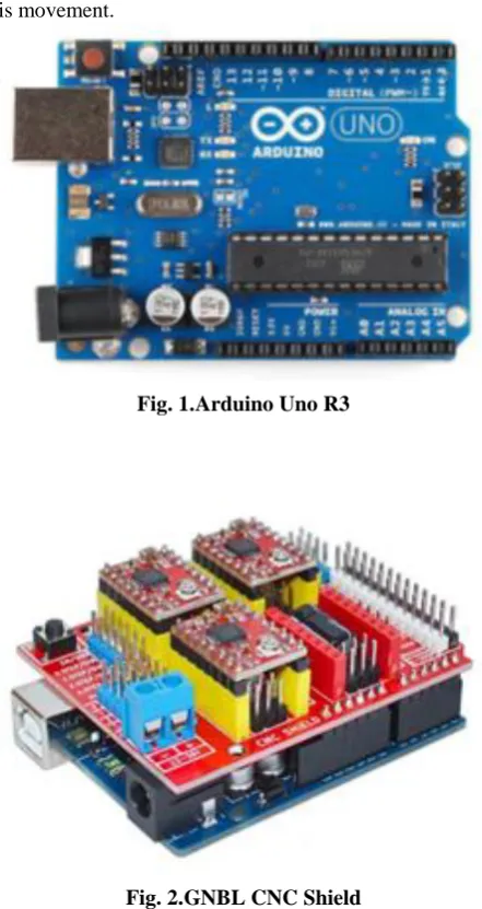
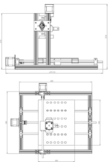
This machine is controlled by Arduino Uno programming that integrated with GRBL CNC Shield. Arduino Uno is microcontroller based on ATmega328P Atmel AVR family microcontroller (MCU). The dimensions of Arduino Uno measured are [68.6 mm x 53.4 mm]. Figure 2.1 shows the Arduino Uno R3 circuit. GRBL CNC shield It is open-source software and hardware design and manufactures a single of the microcontroller. GRBL CNC shield will control the motor driver for stepper motor by using GRBL controller software. GRBL is a free, open-source, high-performance software for controlling the motion of machines and will run on a straight Arduino. It is designed to send G-code to CNC machines, such as 3D milling machines and router machine. Figure 2.2 shows the GRBL CNC shield can control up to 4
[image:2.595.315.536.52.468.2]axis movement.
[image:2.595.313.536.67.258.2]Fig. 1.Arduino Uno R3
Fig. 2.GNBL CNC Shield
III. MACHINE DESIGN DEVELOPMENT
A. The first stage
For the first primary step in designing a product is data gathering. The process starts with data benchmarking between the existing product in the industry. In this process, 3 existing model of Mini CNC machine is selected. The selection is made base on the specification and fixed base on design consideration to produce the new design of the Mini CNC machine. The machine is selected based on size, and the operation can be conduct, working area, and mechanical mechanism of the machine. Data is organized and analyzed to proceed with the next process of design.
B. Intermediate stage
At this stage, to carry out the conceptual design, Morphological chart is used to produce a conceptual design based on data gathering from the benchmarking process. The morphological chart is a method of generating ideas in an analytical and systematic manner. A table of the primary function of a characteristic of a product is listed. Base on each characteristic of the product several solutions is come out to
solve or achieve the
solution and choice is taken from the existing product in the market or base on the benchmarking process have been conducting. The design is evaluated by using a decision matrix method that rate the function and specialty for each design in figure form. The final design with the best score proceeds to analytical simulation in CAD software to simulate the capability of the design.
C. Final stage
[image:3.595.313.538.114.345.2]The final stage is to implement all the data gathering and simulation result in the final design. The final design goes through detail analysis in term of dimension, material selection, and mechanical movement to apply and implement in the machine. The fabrication process is one of the design processes. Although the design is starting to fabricate the design is still in the development process. Figure 3.1 shows the final design of the machine with its dimension.
Fig. 3.Final machine design with a fundamental dimension
IV. RESULT AND DISCUSSION A. Design Simulation analysis
The final design of the machine is analyzed by using Solidworks 2016 software to simulate the boundary condition and find the breakpoint also capability of the structure to accommodate load and force. The part that analyses is only a critical part that needed strict boundary condition like the lead screw for axis motion. This analysis I conduct to make sure there is no deflection or deformation of machine that can affect the result of the operation. The theoretical calculation has also been conducting to compare with the software result. The underlying boundary condition is provided to simulate the actual working condition.
B. X-axis beam deflection analysis
Table 4.1 shows the boundary condition that applies to software simulation to simulate the working condition of the
system. Figure 4.1 shows the result of software analysis for the X-axis component. The maximum deflection occurs is 0.054 mm at the red spot and the critical spot for this part need to be considered is the green part at rode and lead screw part that deflects between 0.036 mm to 0.022 mm.
Table- I: Boundary condition for the X-axis Boundary condition Data
Mass 1 kg
Lead screw length 340 mm
Lead screw diameter 8 mm
Young Modulus 200 GPa
Fig. 4.Deflection analysis of X-axis
The rode and lead screw are calculated by the theoretical method to compare the result of the simulation for more understanding and help the decision making.
From the theoretical calculation, the maximum deflection occurs at the lead screw is 0.067 mm also very higher compare to software analysis. However, the deflection is still in acceptable condition and don’t affect the result of the machine operation.
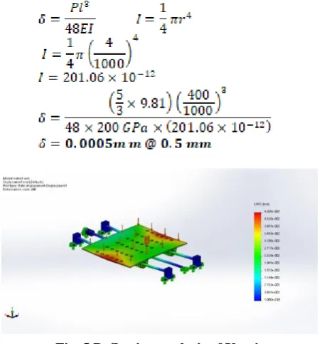
C. Y-axis beam deflection analysis
Table 4.2 shows the boundary condition that applies to software simulation to simulate the working condition of the system. Figure 4.3 shows the result of software analysis for the Y-axis component. The maximum deflection occurs 0.047 mm at the red spot. The critical spot for this Y-axis part needs to be considered is the yellow part at the lead screw component. The deflection at that place is between 0.039 mm to 0.031 mm.
Table- II: Boundary condition for the Y-axis Boundary condition Data
Mass 5 kg (divided equally to table surface)
[image:3.595.77.251.265.526.2] [image:3.595.344.510.415.523.2]Lead screw diameter 8 mm
Young Modulus 200 GPa
[image:4.595.57.284.50.84.2]Comparison between theoretical calculation and the simulation result, the difference is enormous between software analysis and theoretical calculation. In software analysis, the load is applied indirectly to the lead screw. The load is applied on the table that attaches to lead screw by a bearing. The load is not fully divided equally between the lead screw and the guided bar. While for theoretical calculation, the load was directly applied to the lead screw and the load is divided equally to lead screw and guided bar. This is the causes of the differences in the deflection value between theoretical calculation and software analysis. Calculation below shows the value of deflection by using theoretical calculation.
Fig. 5.Deflection analysis of Y-axis
D. Machine accuracy testing
The machine is tested to know the tolerance and capability of the machine to perform a process. During the testing, there are several variables that need to be considered to get an accurate and reliable result. More than one testing is made to compare and analyze the result for more understanding and decision making for nest design development.
The machine is tested to draw a geometry of star shape, rectangular shape, and a polygon shape. After that, the dimension of the geometry is compared between the input dimension and the result produced by the machine. The Gcode is produced by using ABViewer 14 software. This software provides a simple feature to convert geometry shape into Gcode file. After that, the Gcode is transferred into the GRBL controller for the next step of the process. Before beginning the drawing process, simulate and view the geometry shape on the GRBL interface to make sure the dimension and for zero positionings of the tool. The zero positioning is manually made for easy installation and process. During process running, always aware with tool positioning to prevent tool collide or the process is exceed working area limit. Standby to push an emergency button
[image:4.595.312.539.85.154.2]went sudden incident occur. Figure 4.4 shows the flow step of the testing process
Fig. 6.Testing process step flow
The result of the testing is shown in Table 4.3. The data from Gcode for the input is compared with the actual result from the machining process, and the difference is a record in percentage. The higher the percentage, the higher the difference between the two data.
Table- III: Dimension comparison between Gcode data and actual data
Geometry Gcode
(mm)
Actual (mm)
Gcode (mm)
Actual (mm)
Diff Per
Star 100 99.7 100 98.4 0.3/1.6 0.95
Rectangula
r 100
99.8 100 100.2 0.2/0.2 0.2
Polygon 100 100.3 100 99.8 0.3/0.2 0.25
The data show that the highest different is 1.6mm and the average rage of the different is 0.2mm to 0.3mm. The different of 1.6mm is because of human error or tool alignment error during the process. From the data, we can conclude that the machine accuracy is approximate 0.5mm for the drawing process. For another process, the tolerance also needs to consider others factor such as vibration, heat, and speed of the motion.
V. CONCLUSION
As a conclusion, this machine will help and increase the productivity of the product that performs a repetitive task. The worker quickly becomes tedious and their productivity decreasing. It will affect the quality of the production. By eliminating and reduce repetitive task the quality and performant worker increasing along the process. Each process can be done automatically by a machine, and this machine objective is to produce a low cost and efficient machine for small and medium enterprise industry. With this single machine, small and medium enterprise industry can reduce production lost also increasing worker productivity. This machine is fulfilled its objective to reduce human error and reduce repetitive work performed by the worker.
ACKNOWLEDGMENT
The authors extend their appreciation to, Mr. Johan Ihsan Bin Mahmood for providing motivation, and inspiration toward this project.
REFERENCES
1. Anil Kumar, A., Sai Krishna, K. & K., Sai Reddy, R.B.G. (2017). Mini
CNC 2d Sketcher for Accurate Building Drawing.International Journal of Civil Engineering and Technology (IJCIET) Volume 8, Issue 6, June 2017, pp. 543–549, Article ID: IJCIET_08_06_060
2. Anil Kumar, A., Sai Krishna, K., Sai Reddy, R.B.G. and Shakti Prasad,
[image:4.595.56.283.260.502.2]Institute of Technology, 2017.pp. 801–808.
3. Benhabib, Beno. (2003). Manufacturing: Design, Production,
Automation, and Integration. New York: Marcel Dekker.
4. Kajal J. Madekar1, Kranti R. Nanaware2, Pooja R. Phadtare3, Vikas S.
Mane4. (2016). Automatic mini CNC machine for PCB drawing and drilling. International Research Journal of Engineering and Technology (IRJET) Volume: 03 Issue: 02.
5. Kornel F. Ehmann, Rechard E. DeVor, Shiv G. Kapoor. (2002).
Micromesh-scale Mechanical Manufacturing Opportunities and Challenges. JSME/ASME International Conference on Materials and Processing.
6. Markku. S. (2015). Planning of an electric system for a small CNC machine. Seinäjoki University of Applied Sciences.
7. Pabla. B. S., Adithan. M. (1994). CNC Machines. New Delhi, India.
New Age International (P) Limited.
AUTHORS PROFILE
Johan Ihsan Mahmood is working as a lecturer with Universiti Kuala Lumpur Malaysian Spanish Institute (UniKL MSI). He completed his BEng Mechanical from Universiti Sains Malaysia (USM) and his MEng Science from University of New South Wales (UNSW). He also has engineering working experience in manufacturing and R&D from the industry. He is currently a Programme Coordinator for the Programme Bachelor of Engineering Technology in Mechanical Design (BETMD) in UniKL MSI. His research interest is in the field of mechanical design, analysis and CAE. Email: [email protected]
Muhamad Safwan Hilmi is currently pursuing his Bachelor of Engineering Technology in Mechanical Design (BETMD) in Universiti Kuala Lumpur Malaysian Spanish Institute (UniKL MSI). Previously he obtained his Diploma in Product Design and Manufacturing German Malaysian Institute (GMI). His research interest is in the field of
mechanical design and analysis. Email: [email protected]
Dr Pranesh Krishnan is working as a Post-Doctoral Researcher. He completed his PhD and MS degrees at Universiti Malaysia Perlis, Malaysia. He has published over 25 articles in reputed conferences and high impact factor journals. His research interests include signal processing, machine learning, drowsiness research, and