© IPC 1997
Revision A
December 1997
Troubleshooting
for
Printed Board
Manufacture
and Assembly
Developed by
THE INSTITUTEFOR
INTERCONNECTING
AND PACKAGING
Standardization ciples of Standardization as a guiding principle of IPC’s standardization efforts.
Standards Should:
• Show relationship to DFM & DFE • Minimize time to market
• Contain simple (simplified) language • Just include spec information • Focus on end product performance
• Include a feed back system on use and problems for future improvement
Standards Should Not:
• Inhibit innovation • Increase time-to-market • Keep people out • Increase cycle time
• Tell you how to make something
• Contain anything that cannot be defended with data
Notice IPC Standards and Publications are designed to serve the public interest through
eliminating misunderstandings between manufacturers and purchasers, facilitat-ing interchangeability and improvement of products, and assistfacilitat-ing the pur-chaser in selecting and obtaining with minimum delay the proper product for his particular need. Existence of such Standards and Publications shall not in any respect preclude any member or nonmember of IPC from manufacturing or selling products not conforming to such Standards and Publication, nor shall the existence of such Standards and Publications preclude their voluntary use by those other than IPC members, whether the standard is to be used either domestically or internationally.
Recommended Standards and Publications are adopted by IPC without regard to whether their adoption may involve patents on articles, materials, or processes. By such action, IPC does not assume any liability to any patent owner, nor do they assume any obligation whatever to parties adopting the Recommended Standard or Publication. Users are also wholly responsible for protecting themselves against all claims of liabilities for patent infringement.
Troubleshooting for
Printed Board Manufacture
and Assembly
Developed by the Process Effects Handbook Subcommittee of the Process Control Management Committee of the Institute for Interconnecting and Packaging Electronic Circuits
Users of this standard are encouraged to participate in the development of future revisions.
Contact:
IPC
2215 Sanders Road Northbrook, Illinois 60062-6135 Tel 847 509.9700
T
HEI
NSTITUTE FORI
NTERCONNECTINGAND
P
ACKAGINGAcknowledgment
Any Standard involving a complex technology draws material from a vast number of sources. While the principal members of the IPC Process Effects Handbook Subcommittee (7-23) of the Process Control Management Committee (7-20) are shown below, it is not possible to include all of those who assisted in the evolution of this standard. To each of them, the members of the IPC extend their gratitude.
Process Control Management Committee
Process Effects Handbook Subcommittee
Technical Liaison of the IPC Board of Directors
Chairman
Patricia J. Goldman PPG Industries, Inc.
Chairman
Patricia J. Goldman PPG Industries, Inc.
Thomas White Hallmark Circuits
Process Effects Handbook Subcommittee
Edward Masami, Aoki Hewlett Packard Laboratories
Lance Auer, Hughes Missile Systems Company
Donald Ball, Atotech USA Inc. Roger Benson, Grace Specialty
Polymers
Austin Blew, Lehighton Electronics Inc.
David Boggs, Merix Corporation Douglas Brauns, Boeing Defense &
Space Group
Kenneth Bridges, Morton Electronic Materials
Gary Briney, E. I. du Pont de Nemours and Company
Stephen Bruton, Sanmina Corporation John Burg, 3M Company
Peter Marc Carter, Rockwell International
Clifford Chaif, Circo Craft Co. Inc. Edward Couble, Shipley Company
L.L.C.
G. Sidney Cox, E. I. du Pont de Nemours and Company
Joseph D’Ambrisi, MacDermid Inc. Karl Dietz, E. I. du Pont de Nemours
and Company
Frank Durso, MacDermid Inc. Joe Felts, PC World, Division of
Circuit World Corporation
Jeff Ferry, Circuit Repair Corporation Delano Frerichs, Intergraph
Corporation
Pierre Gadoua, Canadian Marconi Company
Judy Gentry, Noble Industries Ltd. Becky Gillmouth, Merix Corporation Patricia Goldman, PPG Industries Inc. Jason Gretton, Matsushita Electronic
Materials Inc.
Kenneth Hafften, The Bureau Electronics Group
Elmer Hayes, Morton Electronic Materials
Glenn Heath, Merix Corporation Daniel Hudson, E. I. du Pont de
Nemours and Company Todd Hutcheson, Rockwell
International
Les Hymes, The Complete Connection David Iguchi, Nelco International
Corporation
Martin Jawitz, Eimer Company John Kelly, Motorola GSTG William Kenyon, Global Centre for
Process Change
Clarence Knapp, Litton Guidance & Control Systems
Stephen Korchynsky, Lockheed Martin Federal Systems
John Lampe, Lockheed Martin Electronics & Missiles
Frederic Lee, Northrop Grumman Norden Systems
Andrea Long, Lucent Technologies Inc.
Candy Maffe, Hadco Corp.
Susan Mansilla, Robisan Laboratory Inc.
Richard Mayes, MacDermid Imaging Technology Inc.
Leland McCrory, Delsen Testing Labs Robert Miller, Methode Electronics
Inc.
Curt Mitchell, General Electric Co. Joseph Mulcahy, Methode Electronics
Inc. East
Charles Mullins, Raytheon Company Daniel Nelson, Coates/ASI
Bob Neves, Microtek Laboratories R. Bruce Officer, Sanders, A Lockheed
Steve Parker, Circuit Center Inc. Pratish Patel, Electronic Interconnect
Corp.
Sukumar Pattnaik, Polyclad Laminates Inc.
James Paulus, AlliedSignal Laminate Systems
Charles Payne, Merix Corporation Paul Quinn, Lockheed Martin Missiles
& Space
Gary Roper, HR Industries Inc. Paul Rose, Lockheed Martin
Electronics & Missiles Roddy Scherff, Printed Circuit
Resources
Friedrich Schlitter, Ruwel & Schoeller GmbH
Robert Seyfert, E. I. du Pont de Nemours and Company Linda Sheldon, Neltec Inc. Robert Shook, Lockheed Martin
Vought Systems
Jeff Shubrooks, Raytheon Company Joseph Slanina, AlliedSignal
Aerospace
Michael Soble, Atotech USA Inc. Lance Sturni, PPG Industries Inc. Edward Surette, M/A-COM Inc. William Thomas, Rockwell
International
Hal Thrasher, Shipley Company L.L.C.
James (Tom) Turner, isolaUSA Kim Van Landingham, E. I. du Pont
de Nemours and Company Nick Virmani, NASA/Goddard Space
Flight Center
Eric Vollmar, Methode Electronics Inc. Debra Weaver, E. I. du Pont de
Nemours and Company
Process Effects Handbook
Table of Contents
1.0 GENERAL INTRODUCTION ... 1
1.1 PURPOSE AND FORMAT... 1
1.2 GUIDELINES FOR EFFECTIVE TROUBLESHOOTING AND PROCESS CONTROL... 1
1.2.1 Problem Identification and Statement ... 1
1.2.2 Immediate Action Plans... 2
1.2.3 Measurement System Evaluation ... 2
1.2.4 Parameter Diagnostics ... 2
1.2.5 Parameter Analysis ... 2
1.2.6 Corrective Action Plan ... 3
1.3 APPLICABLE DOCUMENTS... 3
1.3.1 IPC... 3
1.3.2 Government... 4
1.4 HANDLING... 4
1.4.1 Scratches ... 4
1.4.2 Bending or Flexing Panels ... 4
1.4.3 Fingerprints ... 4
1.4.4 Storage... 4
1.5 BAKING... 5
1.5.1 General Problems Associated With Baking ... 5
1.5.2 Resin Curing ... 5
1.5.3 Stress Relief ... 5
1.5.4 Moisture Removal... 6
1.5.5 Organic Coating Cure... 6
1.6 RINSING... 6
1.6.1 Rinse Time ... 6
1.6.2 Rinse Water Temperature... 7
1.6.3 Agitation to Improve Rinsing... 7
1.6.4 Spray Rinsing... 7
1.6.5 Counterflow Rinsing ... 7
1.6.6 Drip Times ... 7
1.6.7 Special Rinse Techniques ... 8
1.6.8 References ... 9
1.7 PACKAGING... 9
1.8 MAINTENANCE... 9
1.8.1 Process Maintenance... 9
1.8.2 Preventative Maintenance... 9
1.8.3 Corrective Maintenance ... 9
1.8.4 Calibration Program... 9
1.8.5 Housekeeping ... 9
1.8.6 Proces Documentation and Procedures ... 9
2.0 DESIGN AND DOCUMENTATION... 1
2.1 DESIGN... 1
2.2 LAYOUT PROBLEMS... 2
2.3 ELECTRICAL... 2
2.4 MATERIAL... 5
2.5 COMPONENTS... 5
2.6 ASSEMBLY... 6
2.6.1 Component Processing ... 6
2.6.2 Moving Substrates ... 6
2.6.3 Assembly Process ... 7
2.7 PRINTED BOARD FABRICATION... 8
2.7.1 Holes ... 8
2.7.2 Conductors ... 9
2.7.3 Construction ... 9
2.8 BOARD PHYSICAL CHARACTERISTICS... 9
2.9 DOCUMENTATION... 9
2.9.1 Printed Board Master Drawing ... 9
2.9.2 Printed Board Assembly Documentation ... 12
2.10 INSPECTION AND TEST... 12
2.11 RELIABILITY... 13
3.0 PHOTOTOOLING... 1
3.1 MATERIALS AND PROCESSES... 1
3.1.1 General ... 1
3.1.2 Diazo Film ... 1
3.1.3 Silver Halide Film ... 4
3.1.4 Glass - Silver Halide ... 7
3.1.5 Glass - Hard Surface Image on Glass ... 9
3.2 ARTWORK... 9
3.2.1 General ... 10
3.2.2 Manually Prepared Artwork ... 11
3.2.3 Photoplotter-Generated Artwork... 13
3.2.4 Laser-Generated Artwork... 13
3.3 PRODUCTION MASTER... 14
3.3.1 Reduction Problems ... 14
3.3.2 Artwork Modifier Problems ... 15
3.3.3 Step-And-Repeat Problems... 15
3.3.4 Coupons Versus End-Product Quality... 16
3.3.5 Measurement, Inspection and Touch-Up... 19
3.3.6 Direct Imaging (Magnetic Tape) Problems... 19
3.4 WORKING PHOTOTOOL, PRODUCTION MASTER... 19
3.4.1 Handling-Related Problems ... 19
3.4.2 Normalizing-Related Misregistration ... 20
3.4.3 Quality of Contact Prints... 20
3.4.4 Protective Coatings ... 21
3.4.5 Pinning/Registration/Sandwiches ... 21
4.1 GENERAL... 1
4.1.1 Resins ... 1
4.1.2 Reinforcements ... 1
4.1.3 Metal Foils ... 1
4.2 PREPREG OR ‘‘B-STAGE’’... 1
4.3 LAMINATE... 2
4.4 PROBLEMS ASSOCIATED WITH THE BASE MATERIALS ... 2
4.4.1 Material Identification ... 2
4.4.2 Dimensional Stability ... 3
4.4.3 Mechanical Stability ... 3
4.4.4 Foreign Material / Inclusions ... 4
4.4.5 Metal Surface Defects ... 5
4.4.6 Chemical and Thermal Resistance ... 6
4.4.7 Electrical ... 8
5.0 MECHANICAL OPERATIONS... 1
5.1 DRILLING ... 1
5.1.1 Dimensional ... 2
5.1.2 Hole Quality ... 4
5.1.3 Processing ... 7
5.2 PUNCHING (PIERCE AND BLANK)... 7
5.2.1 Dimensional ... 7
5.2.2 Feature Quality ... 8
5.3 ROUTING... 9
5.3.1 Dimensional ... 9
5.4 SHEARING... 11
5.4.1 Dimensional ... 11
5.4.2 Processing ... 11
5.5 BEVELING ... 11
5.5.1 Feature Quality ... 11
5.5.2 Processing ... 12
5.6 SCORING ... 12
5.6.1 Dimensional ... 13
5.6.2 Web Thickness and Web Location ... 13
5.6.3 Score Angle ... 13
5.6.4 Surface Quality ... 13
5.7 LASER DRILLING... 14
5.7.1 Dimensional ... 14
5.7.2 Hole Quality ... 14
5.8 WATER JET CUTTING/PROFILING ... 15
5.8.1 Dimensional ... 15
5.8.2 Feature Quality ... 15
5.8.3 Equipment ... 15
6.0 HOLE PREPARATION... 1
6.1 MECHANICAL ... 1
6.1.1 Deburring and Sanding... 1
6.1.2 Vapor Hone and Abrasive Blast ... 1
6.2 CHEMICAL HOLE PREPARATION ... 2
6.2.1 Resin Removal General ... 3
6.2.2 Alkaline Permanganate Desmearing/Etchback System ... 3
6.2.3 Sulfuric Acid Desmearing/Etchback System ... 4
6.2.4 Chromic Acid Desmearing/Etchback System ... 5
6.2.5 Reinforcement Removal, General ... 7
6.2.6 Ammonium Bifluoride/Hydrochloric Acid Reinforcement Removal ... 8
6.2.7 Hole Roughening ... 8
6.3 PLASMA HOLE PREPARATION... 9
6.3.1 Plasma Smear Removal ... 9
6.3.2 Side Effects ... 10
7.1 HOLE METALLIZATION (CONDITIONING) (Includes Cleaner/Conditioner, Micro-Etch
Solutions and Their Rinses) ... 1
7.1.1. Bath Control... 1
7.1.2 Hole Conditions ... 2
7.1.3 Surface Conditions... 3
7.2 HOLE CATALYZATION (SENSITIZING) (Includes Predip, Catalyst, and Accelerator Baths and Their Rinses)... 4
7.2.1 Bath Control... 4
7.2.2 Hole Conditions ... 4
7.3 HOLE METALLIZATION (Copper Deposition) (Includes Electroless Copper Bath and Rinses) ... 5
7.3.1 Bath Control ... 5
7.3.2 Hole Conditions ... 9
7.3.3 Surface Problems ... 12
7.4 HOLE METALLIZATION (REWORK)... 13
7.5 SEMI-CONDUCTIVE COATINGS... 13
7.5.1 Palladium-Based ... 13
7.5.2 Carbon Black Dispersion Process ... 14
7.6 FULL BUILD ELECTROLESS COPPER... 16
7.6.1 Additive Processing ... 16
7.6.2 Semi-Additive Processing... 18
7.7 DIRECT METALLIZATION DURING DRILL OPERATION... 19
8.0 CLEANING PROCEDURES... 1
8.1 MECHANICAL CLEANING PROCEDURES... 1
8.1.1 General ... 2
8.1.2 After Electroless Plating/Resist Application ... 3
8.1.3 Before Fusing... 4
8.2 CHEMICAL CLEANING PROCEDURES... 4
8.2.1 General ... 4
8.2.2 Solder Conditioning Before Fusing ... 5
8.2.3 Cleaning After Fusing or Hot Air/Oil Level... 6
8.3 ELECTROCLEANING... 6
8.3.1 General ... 7
9.0 IMAGING... 1
9.1 GENERAL... 1
9.2 DRY FILM PHOTORESIST... 1
9.2.1 Common Problems of Dry Film Photoresist ... 2
9.2.2 Total Aqueous Resist ... 11
9.2.3 Semi-Aqueous Resist ... 16
9.2.4 Solvent Resist ... 17
9.3 LIQUID PHOTORESIST... 18
9.3.1 Common Problems of Liquid Photoresist ... 18
9.4 SCREEN PRINTED RESIST... 21
9.4.1 Common Problems of Screen Printed Resist ... 21
9.5 ELECTROPHORETICALLY DEPOSITED PHOTORESIST... 27
9.6 LASER IMAGING OF PHOTORESIST... 27
10.0 ELECTROPLATING... 1
10.1 GENERAL... 1
10.2 COPPER ELECTROPLATING... 4
10.2.1 General ... 4
10.2.2 Copper Sulfate ... 5
10.2.3 Pyrophosphate ... 11
10.2.4 Fluoborate ... 13
10.3 TIN-LEAD... 14
10.3.1 General ... 14
10.3.2 Fluoborate-Based Baths ... 17
10.3.3 Organic Sulfonic Acid (OSA) Based Baths... 18
10.3.4 High-Speed Tin-Lead Plating ... 19
10.3.5 High Throw Tin-Lead Plating ... 20
10.4 TIN... 20
10.4.1 General ... 20
10.4.2 Bright Acid Sulfate Tin ... 20
10.5 NICKEL... 22
10.5.1 General ... 22
10.5.2 Sulfamate Nickel Baths ... 23
10.5.3 Sulfate (Watts) Nickel ... 26
10.6 GOLD PLATING... 28
10.6.1 General ... 28
10.6.2 Gold Strike ... 29
10.6.3 Hard Gold ... 29
10.7 CONTACT PLATING (TAB OR
FINGER PLATING)... 33
10.7.1 Preparation/Masking (Taping or Photoresist Application - Also see 9.2 and 16.4) ... 33
10.7.2 Tin-Lead Stripping... 33
10.7.3 Cleaning ... 34
10.7.4 Plating ... 34
10.8 MISCELLANEOUS PLATING SOLUTIONS... 35
10.8.1 Rhodium ... 35
10.8.2 Palladium... 36
10.8.3 Tin-Nickel Alloy Plating ... 36
10.8.4 Palladium-Nickel... 37
11.0 ETCHING... 1
11.1 GENERAL... 1
11.1.1 Equipment-Related Effects and Effects from Other Processes... 1
11.2 CUPRIC CHLORIDE... 4
11.2.1 Bath Control... 4
11.2.2 Improper Etching ... 5
11.3 ALKALINE (AMMONIACAL) ETCHANTS... 6
11.3.1 Bath Control... 6
11.3.2 Improper Etching ... 7
11.4 PEROXIDE-SULFURIC ETCHANTS... 9
11.4.1 Bath Control... 9
11.4.2 Improper Etching ... 11
11.5 FERRIC CHLORIDE... 11
11.5.1 Bath Control... 11
11.5.2 Improper Etching ... 12
11.6 MISCELLANEOUS ETCHING SOLUTIONS ... 13
11.6.1 Ammonium or Sodium Persulfate... 13
12.0 INNERLAYER FABRICATION... 1
12.1 GENERAL... 1
12.1.1 Handling ... 1
12.1.2 Innerlayer Problems – General ... 1
12.2 PRINT AND ETCH INNERLAYERS... 2
12.2.1 Cleaning ... 2
12.2.2 Resist Residue on Innerlayers ... 2
12.2.3 Imaging ... 2
12.3 INNERLAYERS WITH BLIND AND/OR 12.3.3 Etching ... 2
12.4 COPPER TREATMENT TO IMPROVE LAMINATE ADHESION ... 3
12.4.1 Double Treated Copper/Laminator’s Oxide ... 3
12.4.2 Black or Red/Brown Oxide Coatings ... 4
12.4.3 Oxide Bath Control... 5
12.4.4 Oxide Post Treatment ... 6
12.4.5 Conveyorized Oxide Systems... 7
12.4.6 Delamination Relating to the Application of the Oxide Coating ... 8
13.0 LAMINATION... 1
13.1 GENERAL... 1
13.1.1 Misregistration ... 1
13.1.2 Blisters/Delamation and Interlaminate Adhesion ... 7
13.1.3 Bowing/Twisting ... 7
13.1.4 Laminate Voids ... 7
13.1.5 Resin Starvation ... 7
13.1.6 Panel/Board Thickness... 7
13.1.7 Surface Imperfections ... 7
13.2 HANDLING... 7
13.2.1 Misregistration ... 8
13.2.2 Blisters/Delamination... 8
13.2.3 Laminate Voids ... 8
13.2.4 Surface Imperfections ... 8
13.3 EQUIPMENT... 8
13.3.1 Misregistration ... 9
13.3.2 Blisters/Delamination... 9
13.3.3 Laminate Voids ... 9
13.4 MATERIAL... 9
13.4.1 Misregistration ... 9
13.4.2 Blisters/Delamination... 10
13.4.3 Bow and Twist (Warped)... 10
13.4.4 Laminate Voids ... 10
13.4.5 Resin Starvation ... 11
13.4.6 Panel Thickness... 11
13.4.7 Surface Imperfections ... 11
13.5 TOOLING... 12
13.6 MULTILAYER DESIGN... 13
13.6.1 Misregistration ... 13
13.6.2 Blisters/Delamination... 14
13.6.3 Bow and Twist (Warped) ... 14
13.6.4 Laminate Voids ... 14
13.6.5 Resin Starvation ... 14
13.6.6 Panel Thickness ... 15
13.7 INNERLAYER PREPARATION... 15
13.7.1 Misregistration ... 15
13.7.2 Blisters/Delamination ... 16
13.7.3 Laminate Voids ... 18
13.8 PREPREG (B-STAGE) PREPARATION... 18
13.8.1 Blisters/Delamination... 18
13.8.2 Laminate Voids ... 19
13.8.3 Panel Thickness ... 19
13.9 COPPER FOIL PREPARATION... 19
13.9.1 Blisters/Delamination... 19
13.9.2 Surface Imperfections ... 19
13.10 LAY UP... 19
13.10.1 Blisters/Delamination ... 19
13.10.2 Bow and Twist (Warped) ... 20
13.10.3 Panel Thickness ... 20
13.10.4 Surface Imperfections ... 20
13.11 PRESSING... 21
13.11.1 Misregistration ... 21
13.11.2 Blisters/Delamination... 21
13.11.3 Bow and Twist (Warped) ... 22
13.11.4 Laminate Voids ... 23
13.11.5 Resin Starvation ... 23
13.11.6 Panel Thickness ... 24
13.12 POST LAMINATION BAKE ... 25
13.12.1 Blisters/Delamination ... 25
13.12.2 Bow and Twist (Warped)... 25
13.12.3 Surface Imperfections ... 25
13.13 SUBSEQUENT PROCESSING... 25
13.13.1 Misregistration ... 25
13.13.2 Blisters/Delamination... 26
13.13.3 Bow and Twist (Warped)... 26
13.13.4 Voids in Plated Through Holes ... 26
14.0 METALLIC PROTECTIVE COATINGS... 1
14.1 TIN-LEAD FUSING... 1
14.1.1 General ... 1
14.1.2 Infra-red Fusing ... 3
14.1.3 Hot Oil Reflow ... 3
14.1.4 Vapor Phase Fusing ... 4
14.2 SOLDER LEVELING... 4
14.2.1 Hot Air Leveling... 4
14.2.2 Machine/Material Problems... 5
14.3 IMMERSION COATINGS... 6
14.3.1 Immersion Tin... 6
14.3.2 Immersion Gold ... 7
14.3.3 Immersion Tin-Lead ... 8
14.4 ELECTROLESS COATINGS... 9
14.4.1 Electroless Nickel ... 9
14.4.2 Electroless Tin... 11
15.0 NON-METALLIC PROTECTIVE COATINGS... 1
15.1 PERMANENT SOLDER RESIST... 1
15.1.1 Screen Printable Solder Resists (Thermal and UV Cure) ... 1
15.1.2 Dry Film Solder Resist ... 5
15.1.3 Liquid Photoimageable (LPI) Solder Resist ... 9
15.2 TEMPORARY PROTECTIVE COATINGS... 14
15.2.1 Inhibitor Coatings ... 14
15.2.2 Rosin-/Resin-Based Coatings (Prefluxes) ... 14
15.2.3 Chromate Inhibitor Coatings ... 15
15.2.4 Copper Oxidation (Also see Section 12.4) ... 15
15.3 TEMPORARY SOLDER RESISTS... 16
15.3.1 Tape ... 16
15.4 NOMENCLATURE (LEGEND) -NON-METALLIC MATERIALS... 17
15.4.1 Screen-Printed ... 17
15.4.2 Photoimageable ... 18
16.1 GENERAL... 1
16.1.1 Electrostatic Discharge (ESD) Concerns ... 1
16.1.2 Component Leads ... 1
16.1.3 Storage ... 1
16.2 COMPONENT PREPARATION... 1
16.2.1 Pre-Tinning ... 1
16.2.2 Pre-Forming ... 1
16.3 BOARD PREPARATION ... 2
16.3.1 Pre-Assembly Bake... 2
16.4 COMPONENT INSERTION (THROUGH-HOLE).. 3
16.4.1 Manual/Semi-Automatic ... 3
16.5 COMPONENT PLACEMENT SURFACE
MOUNT ... 5
16.5.1 Adhesive Application ... 5
16.5.2 Solder Paste Application ... 7
16.5.3 Component Placement (Surface Mount) ... 19
16.6 CHIP-ON-BOARD (Unpackaged Chip Components) ... 23
16.6.1 Wire Bonding ... 23
16.6.2 TAB Bonding ... 23
17.1 GENERAL... 1
17.1.1 General Observed Conditions... 1
17.2 SOLDERING MATERIALS... 1
17.2.1 Adhesives (See Section 16.5.1, Adhesive Application)... 1
17.2.2 Solder Paste (Also see Section 16.5.2, Solder Paste Application) ... 2
17.2.3 Flux (See Section 17.4, Wave Soldering) .... 2
17.2.4 Solder (See Section 17.4, Wave Soldering) ... 2
17.3 MANUAL (HAND) SOLDERING... 2
17.4 WAVE SOLDERING... 3
17.4.1 Equipment Related Problems ... 3
17.4.2 Material/Prior Process Related Problems... 5
17.4.3 Design Related Problems ... 7
17.5 VAPOR PHASE SOLDERING... 8
17.5.1 Equipment/Process Related Problems ... 8
17.5.2 Material/Prior-Process Related Problems.... 10
17.6 INFRARED/CONVECTION REFLOW SOLDERING... 12
17.6.1 Equipment/Process Related Problems ... 12
17.6.2 Material/Prior-Process Related Problems.... 14
18.1 CLEANING... 1
18.1.1 Solder Flux Removal ... 1
18.1.2 Legend Ink Removal ... 5
18.1.3 Pre-encapsulation Cleaning ... 6
19.0 POST SOLDERING PROCESSES... 1
19.1 CONFORMAL COATING... 1
19.1.1 General Problems... 3
19.1.2 Polyurethane Conformal Coatings ... 4
19.1.3 Silicone Conformal Coatings ... 5
19.1.4 Paraxylylene Conformal Coating ... 5
20.0 INSPECTION AND TEST... 1
20.1 METHODS OF INSPECTION AND TEST... 1
20.1.1 Equipment ... 1
20.1.2 Personnel ... 1
20.2 CLEANLINESS... 1
20.2.1 Ionic contamination ... 1
20.2.2 Organic Contamination... 2
20.3 ELECTRICAL TESTING... 2
20.3.1 Moisture and Insulation Resistance ... 2
20.3.2 Insulation Resistance As Received ... 3
20.3.3 Dielectric Withstand ... 3
20.3.4 Surface Insulation Resistance... 3
20.3.5 Electrical Continuity ... 3
20.3.6 Isolation (Shorts)... 4
20.4 VISUAL AND AUTOMATIC OPTICAL INSPECTION... 4
20.4.1 Visual Inspection... 4
20.4.2 Automated Optical Inspection (AOI)... 6
20.5 THERMAL STRESS (Solder Float)... 7
20.5.1 Coupon Conditioning and Thermal Stress ... 7
20.6 MICROSECTIONING... 8
20.6.1 Microsection Preparation ... 8
20.6.2 Microsection Etching ... 10
20.6.3 Microsection Evaluation ... 11
20.7 OTHER TEST METHODS... 12
20.7.1 Thermal Shock ... 12
20.7.2 Tensile Strength and Elongation ... 13
20.7.3 Bond Strength of Surface Mount Lands ... 13
20.7.4 Rework Simulation ... 14
20.7.5 Gold Porosity Testing ... 14
20.7.6 Copper Hole Wall Thickness Using Caviderm Type Resistance Measurements.. 14
20.7.7 Plating Thickness (Beta Backscatter)... 15
20.7.8 Plating Thickness (X-Ray Fluorescence) .... 15
21.0 MODIFICATION, REWORK AND REPAIR... 1
21.1 TERMS AND DEFINITIONS... 1
21.1.2 Rework ... 1
21.1.3 Repair ... 1
Section 1
General Information
Table of Contents
1.0 GENERAL INTRODUCTION ... 1
1.1 PURPOSE AND FORMAT... 1
1.2 GUIDELINES FOR EFFECTIVE TROUBLESHOOTING AND PROCESS CONTROL... 1
1.2.1 Problem Identification and Statement ... 1
1.2.2 Immediate Action Plans... 2
1.2.3 Measurement System Evaluation ... 2
1.2.4 Parameter Diagnostics ... 2
1.2.5 Parameter Analysis ... 2
1.2.6 Corrective Action Plan ... 3
1.3 APPLICABLE DOCUMENTS... 3
1.3.1 IPC... 3
1.3.2 Government... 4
1.4 HANDLING... 4
1.4.1 Scratches ... 4
1.4.2 Bending or Flexing Panels ... 4
1.4.3 Fingerprints ... 4
1.4.4 Storage... 4
1.5 BAKING... 5
1.5.1 General Problems Associated With Baking ... 5
1.5.2 Resin Curing ... 5
1.5.3 Stress Relief ... 5
1.5.4 Moisture Removal... 6
1.5.5 Organic Coating Cure... 6
1.6 RINSING... 6
1.6.1 Rinse Time ... 6
1.6.2 Rinse Water Temperature... 7
1.6.3 Agitation to Improve Rinsing... 7
1.6.4 Spray Rinsing... 7
1.6.5 Counterflow Rinsing ... 7
1.6.6 Drip Times ... 7
1.6.7 Special Rinse Techniques ... 8
1.6.8 References ... 9
1.7 PACKAGING... 9
1.8 MAINTENANCE... 9
1.8.1 Process Maintenance... 9
1.8.2 Preventative Maintenance... 9
1.8.3 Corrective Maintenance ... 9
1.8.4 Calibration Program... 9
1.8.5 Housekeeping ... 9
1.8.6 Proces Documentation and Procedures ... 9
Figures Figure 1–1 Example of counterflow rinsing ... 8
This Page
Intentionally
Section 1
General Introduction
1.0 GENERAL INTRODUCTION
The Process Effects Committee of the IPC has developed this Process Control Handbook for Printed Board Manufac-ture and Assembly, which is a documentation of problems, and the corrective action that may be taken. The inputs were voluntarily established by technical representatives of IPC member companies, and have been reviewed in open discussion at the Process Effects Handbook meetings prior to publication.
New inputs are encouraged to help assure that the future Process Control Handbooks are complete and match the latest state-of-the-art in a particular subject. All new or revised information will go through an approval cycle, so that the material contained in the Handbook represents the best consensus of the industry at large.
1.1 PURPOSE AND FORMAT The purpose of this Hand-book is to provide guidance in the form of troubleshooting examples, process cause and effect information and statis-tical methods for correcting problems in all areas relating to the design, manufacture, assembly, and test of printed wiring products. A comprehensive Table of Contents deals with all of the various aspects of the design through deliv-ery cycle. At times there may be duplication in the mate-rial presented, however, in many instances the matemate-rial is cross referenced.
The Guide has been segmented into 21 major sections:
1.0 General Introduction 2.0 Design and Documentation 3.0 Phototooling
4.0 Base Materials 5.0 Mechanical Operations 6.0 Hole Preparation 7.0 Electroless Processes 8.0 Cleaning of Printed Boards 9.0 Imaging Processes
10.0 Electroplating 11.0 Etching
12.0 Innerlayer Fabrication 13.0 Lamination
14.0 Metallic Protective Coatings 15.0 Non-metallic Protective Coatings 16.0 Component Mounting
17.0 Soldering Processes
18.0 Cleaning of Printed Board Assemblies 19.0 Post Solder Process
20.0 Inspection and Test
21.0 Rework, Repair and Modification
The Handbook also contains an index which helps to pro-vide the user with the relationship between the various sec-tions. The Process Control Handbook follows a format:
1. Problem Identification (as specifically as possible)
2. Possible Causes
3. Methods to select which causes apply (when available)
4. Suggested corrective actions/control methods
Where available, an illustration is included to aid in clearly identifying the problem. Examples or tutorials (in bold out-line) are provided in many areas. These may take several forms (e.g., SPC tools, recommended procedures, designed experiments, case histories, etc.) and should not be consid-ered all-inclusive. All processes are, to some degree, unique and there is no substitute for thoughtful local input.
General instruction may at times be provided. Text will be printed across the page, dealing with the subject in general, and not highlighting a problem, cause, or corrective action.
1.2 GUIDELINES FOR EFFECTIVE TROUBLESHOOTING AND PROCESS CONTROL One of the keys to effective problem solving is a structured routine that addresses key points each time a problem is encountered. This section suggests steps to be taken in order to effectively find the cause of a problem and to solve it permanently. Refer to IPC-PC-90 for greater detail to suggested methodology for practical troubleshooting.
1.2.1 Problem Identification and Statement Before beginning a detailed troubleshooting project, use common sense in defining the problem. Verify that there is a prob-lem. Observe the defective product and compare to the standard. Identify the standard process and product, then determine any present deviation from the standard, or any change in the product.
Establish whether operating procedures were followed and whether an assignable cause can be quickly identified as the reason behind the problem. Only continue into more detailed analysis if the initial questions do not lead to an obvious answer. Even if the answer appears to be obvious, confirm the answer by operation of the process before clos-ing the project.
Develop a clear, concise problem statement that quantifies the problem whenever possible and reduces the scope of the investigation to a manageable size.
Existing process data can be used to identify the most important subsets of the problem and better focus trouble-shooting efforts. If the requirement is qualitative, establish a clear, common and understood definition of acceptance criteria.
1.2.2 Immediate Action Plans Every problem experi-enced should be addressed, using an appropriate action plan, by someone designated as the individual responsible. The solution to each problem varies in urgency and inten-sity, however a documented procedure or plan should exist that describes the decision making processes, such as:
1. Emergency problems (fire, chemical spills, etc.) require immediate action.
2. Producing out-of-specification parts require immediate action (i.e., shut down the process).
3. Out-of-control processes require determination as to whether the process can continue to operate.
4. Severe process variation requires evaluation of the severity and effect of the problem on the final product.
The action plan should include the procedures for address-ing products produced duraddress-ing of-specification or out-of-control conditions. The plan should also indicate who should make those decisions. These issues include but are not limited to:
A. Disposition of the defective material (repair, scrap, replace, etc.)
B. Checking the effect on scheduled delivery.
C. Informing the effect on scheduled delivery.
D. Request for non-conformance authority or Material Review Board (MRB) action.
Once the immediate problem is under control, the decision must be made to determine a failure analysis plan, respon-sibility and schedule in order to reduce or eliminate the likelihood of recurrence.
1.2.3 Measurement System Evaluation ‘‘Measurement System’’ in this context refers to the means used to detect and identify the problem. This includes not only the suring apparatus, but also the sampling method, the mea-suring personnel (and their instructions), accuracy and cali-bration of equipment, and environmental factors (i.e., lighting, temperature, and relative humidity). The measure-ment system must adequately measure the variation in the parameter or attribute which is considered critical.
Impre-ments of 0.005 mm cannot reliably be measured with a 30 power shop scope with a reticle scaled in 2 mil increments.
Decisions based on poorly understood measurement sys-tems can be a major cause of misapplied manpower and missed opportunities. Before any statistical decisions can be made, the variation in the measurement must be under-stood. Occasionally correction of a problem in measure-ment can be a solution.
The variation inherent in the measurement of attribute data and responses that are subjective in nature can be addressed. The evaluation is more complex in nature, but it is still an essential part of the analysis of the problem. Sec-tion 6.0 of IPC-PC-90 discusses this subject in greater detail.
1.2.4 Parameter Diagnostics The purpose of Parameter Analysis, as detailed in Section 9 of IPC-PC-90, is to iden-tify, isolate and rank major sources of variation. Further evaluation of the problem can be better focused if the nature of the variation is understood. Common sources are Positional Variation (within a piece), Cyclical Variation (piece to piece) and Temporal Variation (over time). Infor-mation gathered in this effort can be used to modify the Problem Statement if appropriate.
1.2.5 Parameter Analysis The purpose of Parameter Analysis, as detailed in Section 9 of IPC-PC-90, is to iden-tify cause-effect relationships. This step of the trouble-shooting process can be handled in various ways, but a common and effective routine is given here as reference.
1.2.5.1 Brainstorming The development of a cause-and-effect diagram by a cross-functional problem solving team is critical to the identification of variables to be stud-ied. Care should be taken to include representatives of the disciplines that are part of the process being studied, such as engineering, quality, manufacturing operators, analysis laboratory, etc.
Identify all possible causes of the problem, including pro-cess steps, raw materials, materials handling, inspection and personnel. The ranking of these factors by the problem solving team should be used to establish those factors that will be studied experimentally. While engineers are nor-mally responsible for troubleshooting, they should take care to openly consider new ideas on the problem. The insight of manufacturing personnel that are intimate with a process can be invaluable.
experi-1.2.5.2 ‘‘Divide and Conquer’’ Approach List all pro-cess steps in sequence. Examine product halfway through process for defects or its possible cause (is the problem there yet?). Keep on dividing until the exact process step causing the problem is located. Also, make use of other information sources, such as suppliers and available litera-ture (i.e., IPC-PE-740).
1.2.5.3 Process Audit Conduct a process audit by reviewing the entire operation (e.g., documentation, trans-fer, handling, processing, etc.). Identify current conditions and compare to the standard. Define process windows. An audit is best conducted by someone not directly involved in the day-to-day operation of the process.
1.2.5.4 Initial Capability Assessment Process Capabil-ity Studies ideally are done before the process is accepted for production. This means creating a match between the process and the product, and results in a Process Control Window that is capable of producing the product.
One approach to troubleshooting that quantifies improve-ment for reporting to manageimprove-ment involves the use of Capability Assessment. Section 7 of IPC-PC-90 discusses the generation of capability indices in greater detail. This step promotes the clear understanding of the process matri-ces but does require time and resourmatri-ces.
1.2.5.5 Optimization This step includes the variety of techniques used to isolate factors that affect the response being studied. Full and fractional factorial matrices are the most common tools used for this purpose. While some simple problems may not seem to require rigorous experi-mentation, proper technique must still be used when mak-ing one-factor-at-a-time changes. Comparison of the output at both settings is mandatory to establish the real effect of the process change. Outside factors that are not controlled when a new factor setting is evaluated can cause incorrect conclusions to be drawn. Always run a control!
1.2.5.6 Confirmation and Final Capability Assessment After determination of preferred settings for those factors studied, a confirmation run must be performed to establish the performance of the modified process. This step often consists of a Short-Term Capability Analysis for compari-son with the initial capability assessment. A quantitative comparison of indices can be easily understood by unin-volved parties such as management. Only after confirma-tion of the test results should process changes be made.
1.2.5.7 Parameter Control At this point, the factors that significantly impact the identified problem are understood and must be controlled. Section 10 of IPC-PC-90 discusses Parameter Control in detail. If the Tolerance band for these parameters is not clearly understood, more advanced
experimental techniques can be used to establish specifica-tion limits.
A common misapplication of Control chart techniques occurs when variables that are easily measured are charted. Unless the relationship between a variable and the output of a process is understood, this data has little use. The main purpose of Parameter Control is the maintenance of the improvements achieved during earlier efforts. The knowl-edge gained in the Parameter diagnostics step must be used when establishing subgroups for control charting. Failure to capture the important sources of variation can lead to misleading control charts.
1.2.6 Corrective Action Plan When a problem is located, recommend required course of action, then follow it up to assure that it is understood and implemented.
Determine what measures must be taken to prevent recur-rence. Document the problem and solution. Redefine the process control window. Set up permanent controls to keep the variables within the set limits. These may include:
a. Process audits at specified intervals
b. Process control or parameter measurement reporting (control charts, etc.).
c. Preventative maintenance to keep equipment function-ing at established levels.
Report the problem and the corrective action to the appro-priate people.
1.3 APPLICABLE DOCUMENTS The following docu-ments of the issue currently in effect, form a part of this Guide to the extent specified herein.
1.3.1 IPC
IPC-T-50 Terms and Definitions
IPC-PC-90 General Requirements for Implementation of Statistical Process Control
IPC-D-310 Guidelines for Artwork Generation and Mea-surement Techniques
IPC-D-325 Documentation Requirements for Printed Boards
IPC-A-600 Acceptability of Printed Boards
IPC-A-610 Acceptability of Printed Board Assemblies
IPC-TM-650 IPC Test Methods Manual
IPC-2221 Generic Standard on PWB Design
IPC-6011 Generic Performance Specification for Printed Boards
IPC-6012 Qualification and Performance Specification for Rigid Printed Boards
IPC-7711 Rework of Electronic Assemblies
IPC-7721 Repair and Modification of Printed Boards and Electronic Assemblies
Other IPC documents are referenced in the text at the point of interest.
1.3.2 Government
1.3.2.1 Federal Specifications
PPP-B-566 Box, Folding, Paperboard
PPP-B-676 Boxes, Setup
1.4 HANDLING Handling of printed wiring products in all phases is often a major cause of problems and defects that are noted later in the end products. A general lack of concern for handling tools, raw materials, equipment, or end products can easily result in the production of a prod-uct that is substandard.
Many companies have adopted policies that strive to let the employees know the care and attention that must be placed on all aspects of the manufacturing and assembly cycles. This starts with the basis for handling and storage of incoming raw materials and continues into the attitude of personnel working in phototooling (handling of artwork area, humidity, and temperature control).
On the production line, discrepancies in procedures are many times noted where no rigid process controls are used to control layer placement procedures, drill speeds and feed rates, sharpening and replacing of drill bits, proper smear removal, insufficient baking and rinsing cycles, incorrect ratio of plating constituents, incorrect orientation of panels and plating tanks, contaminated plating baths, lack of plat-ing bath analysis, and poor microsectionplat-ing - or no pro-gram at all.
The above list, although not exclusively dealing with han-dling procedures, provides an overview of the conditions that many times lead into the problems detailed in this Guide.
Appropriate employee attitude, coupled with concrete and well defined company procedures will help, not only to control the areas of problems, but to provide a trace back and identification of the failure mechanisms which caused a particular problem.
1.4.1 Scratches Copper-clad panels are surprisingly eas-ily scratched—usually by another copper-clad panel. Scratches and gouges in the copper surface can affect the imaging and etching processes, creating opens or shorts. Panels should not be dragged across each other or across any abrasive surface.
Resist-coated panels (ready for etching or plating) are extremely vulnerable to scratches. While the resists are able to withstand corrosive plating solutions, they are frag-ile when it comes to mechanical damage. Be aware of sharp edges on racks or tanks or other panels. A scratch through the resist will create an open (in etching) or a short (in plating). Scratches on phototools can lead to similar defects.
1.4.2 Bending or Flexing Panels Thin material is some-what more susceptible but the results can be the same. Excessive bending or flexing of panels can damage the resin-to-glass bond in the laminate. This can appear as crazing or measling and can affect the material dielectric and resistance to chemical baths. If a multilayer board is flexed, internal delamination can occur and the entire board integrity destroyed.
1.4.3 Fingerprints Fingerprints can be the scourge of a printed board shop, from the phototool area through final inspection, and all process steps in between. Fingerprints can affect light transmission and therefore the quality of the printing operation in the phototool area and in the imaging area. Fingerprints can affect adhesion—in the resist lamina-tion area, in the plating areas, in the multilayer laminalamina-tion area. Some fingerprints do not clean easily in electroless or electroplating cleaners. The copper does not microetch well and subsequent plating adhesion may suffer. Some people’s fingerprints can actually etch the copper surface. In some cases heavy fingerprints may affect the electrical test opera-tion by acting as an insulator. At final inspecopera-tion, finger-prints could affect board cleanliness and ionic contamina-tion levels.
areas. High temperature and humidity can oxidize clean copper surfaces, as can chemical fumes from the plating area. Strong lighting may adversely affect resist-coated panels even after development. Boards in-process should be stored in clean, dry areas of the shop if at all possible, or processed as soon as possible. Other critical storage points are: oxide-coated innerlayers prior to lamination; prepreg which is temperature and humidity sensitive; all phototools and screens and their associated processing areas (imaging and screen-printing); panels prior to resist lamination through coat, image and develop; after electro-less copper (the somewhat porous surface can absorb other airborne contaminants).
1.5 BAKING Laminate materials are baked several times during the manufacture of a printed wiring board. There are four major reasons for baking:
1. To insure proper cure of the laminate resin.
2. To relieve stresses that may impact the dimensional sta-bility of the laminate.
3. To remove volatiles, e.g., moisture.
4. To cure any organic coatings that may be applied to the laminate (e.g., thermal cure solder mask).
1.5.1 General Problems Associated With Baking
1.5.1.1 Cross Contamination Certain baking operations volatize (drive off) materials which may contaminate sub-sequent work process through the oven. Consider separate ovens for these functions, improved venting, or more fre-quent cleaning.
1.5.1.2 Excessive Baking (Temperature Or
Over-Time) In addition to excessive oxidation of metallic clad-ding, excessive baking can change mechanical and/or chemical properties of some laminates. Verification of actual oven temperatures (vs. set points) and a mechanism for enforcing removal at the specified time are required.
1.5.1.3 Improper Loading Stacking can result in uneven time/temperature profiles with variation in results. Stacking also has the potential for trapping contaminants between laminates at high temperatures, possibly degrading the metallic cladding’s surface. Racks or frames improperly designed or maintained can lead to surface damage.
1.5.1.4 Hold Time After Bake Uncontrolled dwell times after bake can defeat the original purpose of the bake, espe-cially moisture removal.
1.5.2 Resin Curing Fully curing the laminate resin is important to increase the laminate resistance to moisture absorption, to reduce drilling smear, and possibly to help
reduce the incidence of copper cracking by increasing the dimensional stability of the finished laminate. Generally, full cure of the initial core laminate is done by the supplier prior to shipment to printed board fabricators. Full cure of composite multilayer PWBs is done by the fabricator based on laminate suppliers recommendations for correct lamina-tion and cure parameters.
A common measurement for completeness of cure is glass transition temperature (Tg) of the laminate resin. The Tgis an indicator of the laminate thermal performance capabil-ity and will vary accordingly to the resin system used. To achieve the Tgspecified by the laminate supplier, the resin must be fully cured. Full cure is accomplished by heating the resin above the Tg and holding it here for a sufficient time to achieve maximum cross linking of the resin system. It is recommended that the PWB manufacturer check with his laminate supplier for the recommended time and tem-perature (to avoid thermally damaging the laminate or excessive cure). Any bake above the resin Tg should be done under pressure/weight.
Two IPC test methods are available to check laminate for its state of cure (evaluating its Tg). One is Thermal Mechanical Analysis of TMA method, IPC-TM-650 Method 2.4.23, the second is the Differential Scanning Calorimetry or DSC Method IPC-TM-650 Method 2.4.25. Because the two methods typically yield different values, the method used should be consistent with that used by the supplier. It is also wise to specify the test method to the supplier.
In order to determine if additional cure is needed, a single sample can be tested two successive times. During the first test, the sample’s cure is advanced by the test which essen-tially acts as a bake (if undercured). If the second test dif-fers significantly, baking is advised. If the two test values are nearly identical, further baking should not be required.
1.5.3 Stress Relief Stresses are inherent in the lamina-tion process and are the result of the naturally occurring mismatch between the various constituents of the laminate coupled with the material manufacturing process. An example of this is the different coefficients of thermal expansion of the copper and resin system. Another example is the remaining stress from the original yarn fabrication where glass strands are twisted and plied.
down is used. In order to prevent bow and twist, the bake and cool down should be done under low pressure or under a uniform weight.
Typical bake times and temperatures for the various lami-nate resins are shown below:
Bake times are ‘‘at temperature,’’ that is, after the material has reached the bake temperature.
1.5.4 Moisture Removal Resin systems used for PWB laminates vary in their tendency to absorb moisture. Some resin systems (such as PTFE) are virtually impervious, oth-ers can be rather hygroscopic. Residual moisture in the laminate has been shown to cause a variety of deleterious effects from measles to blow holes to excessive resin flow during lamination. Because of this, moisture removal bak-ing is advantageous and may be employed at the followbak-ing stages:
• After oxide coating of innerlayers
• After hole preparation
• Before fusing
• Before solder coating/solder leveling
• Before any soldering operation, including wave solder and rework
The bake for moisture and volatile removal is typically done at 100—125°C for 2–4 hours. Panels should be sepa-rated to permit air circulation: stacks of panels will not heat properly and the moisture will not be able to escape. The user must note that the most practical temperature and time conditions must be determined for each facility and each printed board assembly.
When assemblies must be set aside (e.g., secondary
com-1.5.5 Organic Coating Cure Follow supplier’s recom-mendations for each curing or drying process.
1.6 RINSING Water rinsing plays a very important role in the manufacture of printed wiring boards and assemblies. Rinsing is employed at nearly every process step beginning with phototool development. Proper rinsing is especially important in the wet processing cycles such as imaging, etching and plating. Generally, after each exposure to a chemical solution, the printed boards are rinsed by either immersion or spray techniques. This applies to both manu-ally and automaticmanu-ally operated processes.
The quality of the rinsing operation can and does have direct influence on the quality of subsequent processing. Poor rinsing can result in both board and process tank con-tamination, as well as directly contribute to poor quality product and rejects. Improper rinsing can also cause fre-quent bath changes due to contamination, increase waste treatment costs, and create very elusive processing prob-lems.
Improved rinsing techniques often do not require additional water use. Many techniques are both inexpensive and eas-ily implemented, once understood. Some of these tech-niques include air agitation, sprays (continuous, time or pulsed), counterflows, tempering, longer drip times and new rack designs. The sections below discuss the many ways to improve board quality through improved rinsing.
In some areas, an understanding of the incoming water source (i.e., well vs. reservoir, pH, mineral quantity, filtra-tion), as well as any changes in the source can help prevent problems before they occur - or at least provide a place to start pinpointing the problem. Water districts often change water sources at set times during the year. Well water may contain higher quantities of minerals, while reservoirs sometimes have a high content of organic matter, espe-cially when their level is low. It may be necessary to filter or soften incoming water. Some heavily mineralized water can leave deposits on boards or cause precipitation in cer-tain rinse tanks. Carbon filtration could prevent the intro-duction of organics into a critical process.
1.6.1 Rinse Time Longer rinse times generally result in a better rinsed board. Very small holes take longer due to the fluid dynamics involved. Alkaline or caustic solutions typically take longer to rinse than acids. Warm solutions rinse faster than cold. More concentrated solutions require a longer rinse time (and contaminate the rinse tank faster). Closely spaced panels (in a rack) are more difficult to rinse than those spaced far apart or singly.
Table 1−1 Bake Times and Temperatures
Resin Type Tg*
Bake Temperature Time Difunctional Epoxy 130°C 160°C (320°C) 2-4 hours Multifunctional Epoxy 140-150°C 175°C (350°C) 2-4 hours Tetrafunctional Epoxy 150-160°C 150°C (350°C) 2-4 hours
BT Epoxy 180°C 190°C
(375°C)
2-4 hours
Cyanate Ester 245°C 220°C (425°C)
4 hours
Polyimide 260°C 220°C (425°C)
4 hours
1.6.2 Rinse Water Temperature Warm water will rinse a surface faster than cold water. The general rule for chemical reactions states that for every 10°C increase in temperature, the reaction rate doubles. Rinsing (dissolving a material off a surface) can be thought of as a type of reaction. An ideal cold water rinse temperature is 15–24°C. Hot water is usually recommended after alkaline cleaners to speed up the rinsing process. Extremely cold water rinses can be tempered by adding warm water through a commercially available mixing valve. Warm or hot water will oxidize clean copper surfaces faster than cold water.
1.6.3 Agitation to Improve Rinsing The most commonly employed method is air agitation. It is both inexpensive and extremely effective. Air agitation improves rinsing in two ways: by keeping the rinse water mixed so that con-centrated pockets do not occur; and by continuously mov-ing fresh water to the board surface. Air agitation should not be used in rinses immediately after cleaners that foam.
Mechanical agitation of the boards or rack of boards in the rinse tank also aids in rinsing—again by bringing fresh water to the board surface. When the motion is perpendicu-lar to the board, this method also helps to rinse the through-holes by forcing water through them.
A third method of agitation, that is somewhat less effective, is the introduction of rinse water through a sparging sys-tem. Generally the water flow rate is not sufficient to make this as effective as air agitation, unless a pump is used.
1.6.4 Spray Rinsing Sprays can be a very effective way to rinse. Pressurized water quickly removes contaminants and supplies fresh water to the board surface. A single spray rinse tank can serve several processes. There are a few drawbacks to spray rinsing that should be taken into consideration when planning a spray rinse system:
a. When in operation, sprays consume a tremendous amount of water. Therefore, they should be on only when boards are ready to be rinsed. Generally, the sprays are activated automatically by action of a hoist, or are timed. Often intermittent sprays are used.
b. If spray nozzles become clogged, areas of the board may not be properly rinsed.
c. Holes in the board to not rinse as well as the surface. Very small holes must rely on capillary action as the primary rinse mechanism. Since this is a slower process, more spray time may be necessary than would be expected for a surface. Consider a combination immer-sion rinse plus sprays.
d. Sprays are only effective when both sides of the board can be sprayed. When boards are side-by-side in a basket-type rack (such as those used on an electroless line), sprays cannot adequately rinse the inside boards,
since they are shielded by other boards.
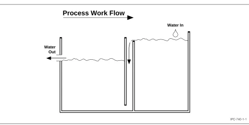
1.6.5 Counterflow Rinsing The diagram below (Figure 1–1) illustrates the principle of counterflow rinsing. Basi-cally, a single water source flows through multiple rinses in a direction opposite or counter to the flow of the work being processed. Counterflow rinses provide the benefit of multiple rinse stations but use the water flow of a single rinse. Therefore, rinsing can be greatly improved without using additional water. Kushner (see references) gives an excellent technical discussion on the benefits of counter-flow rinsing, including calculations to determine required water flow for a given number of rinses.
Both immersion rinse tanks and spray rinse systems can be counterflowed. In an immersion system, the water should be introduced at a spot as far as possible from the outlet. Generally counterflow rinse tanks are joined by a common wall that is an overflow weir, as shown in Figure 1–1. If a process tank separates two rinses, it is possible to exter-nally counterflow the water by piping the outlet of the first to the inlet of the second. Remember that the water flow is by gravity, so the second rinse water height must be slightly lower than the first.
Sometimes the rinse water from one process step can be counterflowed and used at another process step. An example would be a sulfuric acid dip that follows a micro etch step. The rinse water from the acid can be used as rinse water for the micro etch step. It is best to consult the appropriate supplier(s) to insure process compatibility. Some incompatibilities could create precipitates or mix waste streams incorrectly or create later process problems.
In order to counterflow a spray system it is necessary to collect the water from the initial spray into a sump, them pump it to provide the necessary spray can also be reduced by use of a sump and pump system. Counterflowed spray rinses are very common in conveyorized equipment.
1.6.6 Drip Times A major contributing factor to the rinse process is the amount of material carried over on the board into the rinse. Obviously, the less process solution left on the board surface, the less to be rinsed off. There are sev-eral ways to reduce the amount of material carried over, including increased bath temperature and reduced bath con-centration. However, these are limited by the process. A more practical way is to control the drip time of the board(s) over the process solution.
Kushner gives some examples that show the amount of material saved by increased drip times. The material sav-ings and improved rinsing occur in several ways:
a. Less material is dragged out of the process tank result-ing in a chemistry savresult-ings.
c. Less material is on the board surface so there is less to rinse off, therefore the rinse operation is more efficient.
d. Less material needs to be waste treated resulting in a cost savings.
The trade-offs on drip times are time and oxidation of the panel surface. On some large automated lines, drip times can add up and increase the total cycle time. On some pro-cesses, a long drip time may affect the board surface. This generally occurs more easily with heated baths. Process solutions should never be allowed to dry on the board sur-face. Dried-on salts often will not redissolve in the rinse station.
Recommended drip times over process tanks are 10 to 30 seconds. Some drip times over rinse tanks (especially the one immediately following a process tank) are also benefi-cial. Generally 3 to 10 seconds are used. Angling the boards in their racks, so that a corner is the lowest point, also improves dripping.
In the case of conveyorized systems, whether vertical or horizontal, drip times must be re-thought in terms of the pinch rollers that tend to wipe the board surfaces of process chemistry. The tighter and more compliant these rollers are to the board surface, the better the surface is wiped and the less amount of material carried over. Also, the slower the conveyor speed, the less material carried over.
a. Conductivity meters and/or flow restrictors. A conduc-tivity meter will activate the water flow when contami-nation levels in the rinse tank exceed a certain limit. Restrictors simply limit the flow volume. Timers are also placed on rinses so that water is not wasted when no parts are being rinsed. These methods are fine, pro-vided they have been properly set-up and are monitored.
Changes in incoming water pressure or quality, increased product flow through the rinses, or changes in the processes could all adversely affect the rinse quality. In addition, conductivity meters must be calibrated regularly. Flow restrictors tend to age and deteriorate (some actually shrink, further restricting flow). Actual rinse flow rates should be routinely measured as part of a preventive maintenance item.
b. Pulse Sprays. Beyer discusses these in IPC Technical Paper IPC-TP-376. Basically, water sprays are on for several seconds, then off to allow contaminated water to drip off. This cycle is repeated until the board is suffi-ciently rinsed.
c. Air Blow-off. Also discussed by Beyer, this procedure involves air knives near the solution surface. Care must be taken to not allow the board to dry or to create excess foam.
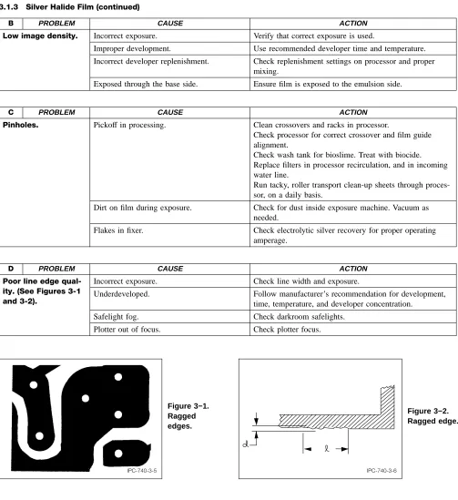
[image:20.612.44.544.52.303.2]d. Sweeping Sprays. Sometimes foam forms on rinse tanks that is then carried down the line. It can be a frustrating source of contamination and is often difficult to keep off IPC-740-1-1
Figure 1–1 Example of counterflow rinsing
Water In
Process Work Flow
▼
▼
▼
e. Fog Sprays. Fog sprays use very little water and are designed to be used over a process tank. Their purpose is to aid in dripping, to keep process solution in the pro-cess tank.
f. Top Sprays. To gain an extra rinse without additional space or tank, sprays can be installed at the top of an immersion rinse tank. As the boards exit the rinse tank, the top sprays are activated as a final clean rinse. The top spray water can also serve as the water input to the tank.
g. Hoist Spray Systems. A design out of Europe encloses a spray rinse system in the hoist. This permits rinsing immediately after the boards have been drawn out of the solution and into the hoist chamber. Rinsing can be done while the hoist is traveling to its next position. There is a space savings in that no rinse tanks are needed on the process line.
1.6.8 References
Water and Waste Control for the Plating Shop, 2nd ed.
Kushner and Kushner, Gardner Press
IPC-TP-376, Water Saving Concepts in Automatic Preplate/Electroplate Lines for Printed Circuits, Gustav H. Beyer
1.7 PACKAGING The packaging of printed wiring boards and/or raw materials at incoming is very important. Con-tainers should be of material and form agreed upon by user and supplier, and related to the particular product being packaged or shipped.
The containers or material used for shipping should not introduce gases or chemicals that could be detrimental to the product itself or to the solderability of the board and later assembly steps. Bags or containers made of silicones, sulfur compounds, or polysulfides or processed with these compounds, should not be used.
All parts that are packaged should be clean, dry and pack-aged in a manner that will afford adequate protection against corrosion, deterioration and physical damage from supply source to the first receiving activity.
Where plastic bags are used for packaging printed wiring boards, they should be clean and free from ionic contami-nants. Heat sealing of plastic bags may release volatiles that may contaminate board surfaces.
1.8 MAINTENANCE Maintenance concerns itself with maintaining the process as it was designed. This is needed to assure a consistent product and to prevent accidents.
It should cover everything from the equipment and instru-mentation through process procedures and process controls to housekeeping and environmental controls.
1.8.1 Process Maintenance Process maintenance deals with replenishing process consumables with decontamina-tion and wear of tooling inherent to the process. e.g., con-centration of plating solutions, carbon treatment, drill bit wear, etc.
1.8.2 Preventative Maintenance Preventative mainte-nance is scheduled and designed to replace or repair before catastrophic failure occurs. By instituting a good preventa-tive maintenance program, unscheduled breakdown can be essentially eliminated.
1.8.3 Corrective Maintenance Corrective maintenance is repair following breakdown.
1.8.4 Calibration Program A calibration program is a maintenance program for instruments, gauges and test sets. Periodic comparison with standards are checked and adjusted based on statistical evidence of an out-of-control condition. If the instrument is in control but out-of-spec, work needs to be done to reduce the inherent variation of the instrument to less than or equal to the specification at a 99.73% confidence interval (±3 sigma). After this adjust-ment has been made the instruadjust-ment should be recalibrated. Failure to do so may cause the process to go out of control while the controls appear to be within specification.
1.8.5 Housekeeping Housekeeping looks after removal of all unnecessary items from the work area. Clutter causes accidents, mistakes and delays. Also, good housekeeping reports any cleaning problems caused by equipment break-down or poor maintenance. Getting a small crack repaired may prevent catastrophic failure later when the crack propagates. Good housekeeping shows regard for the equipment, the investment and the product.
Excessive variations in the environment may affect the pro-cess or the health or effectiveness of the workers. For example, photoprocesses are sensitive to dust, temperature and humidity. Workers are sensitive to chemicals, heat and RH.
This Page
Intentionally
Section 2
Design and Documentation
Table of Contents
2.0 DESIGN AND DOCUMENTATION... 1
2.1 DESIGN... 1
2.2 LAYOUT PROBLEMS... 2
2.3 ELECTRICAL... 2
2.4 MATERIAL... 5
2.5 COMPONENTS... 5
2.6. ASSEMBLY... 6
2.6.1 Component Processing ... 6
2.6.2 Moving Substrates ... 6
2.6.3 Assembly Process ... 7
2.7 PRINTED BOARD FABRICATION... 8
2.7.1 Holes ... 8
2.7.2 Conductors ... 9
2.7.3 Construction ... 9
2.8 BOARD PHYSICAL CHARACTERISTICS... 9
2.9 DOCUMENTATION... 9
2.9.1 Printed Board Master Drawing ... 9
2.9.2 Printed Board Assembly Documentation .... 12
2.10 INSPECTION AND TEST... 12
2.11 RELIABILITY... 13
Figures
This Page
Intentionally
Section 2
Design and Documentation
2.0 DESIGN AND DOCUMENTATION
Design of printed boards and printed board assemblies requires a complete understanding of the board manufac-turing process and the assembly and joining processes. Designers must consider manufacturing allowances for conductor definition and plated-through hole to land rela-tionships in order to ensure adequate annular ring defini-tion. In addition, proper clearances for automatic compo-nent insertion or placement equipment heads must be accommodated.
Choice of materials for board construction is important relative to the performance of the electronics assembly in its usage environment. High temperature laminate is used in products that must dissipate extreme heat or are sub-jected to the temperature gradients in the location where the assembly is used (i.e., automotive product that must operate under the hood).
The requirements of the design must be properly docu-mented to ensure proper board fabrication and assembly conditions. Proper documentation requires the definition of all features and tolerances, plus references to any perfor-mance specifications to which the product must adhere. Customer dissatisfaction can result when product perfor-mance expectations are not properly documented and the manufacturer uses his best judgement in order to meet the assumed requirements. Refer to IPC-D-325, Documenta-tion Requirements for Printed Boards.
Section 2 details some of the major problems that occur in the design and documentation processes.
2.1 DESIGN
Design disciplines use manual or automated techniques in order to describe the characteristic of the printed board or printed board assembly. The design principles may be applied to single-sided, double-sided, or multilayer struc-tures. Materials may be organic in nature, either rigid or flexible, or non-organic, such as ceramic or porcelainized steel printed boards.
At times, combinations of different materials are chosen in order to satisfy the design objectives. An example of this would be a rigid-flex multilayer product with a metal core to dissipate the heat from several components. Choosing the proper materials requires an understanding of the end product usage environment and the manufacturing process in order to be able to build the final board at acceptable yield and cost.
There are many computer-aided (CAD) stations available to assist in the design process. Cost of hardware and soft-ware has dropped significantly, so most designers can take advantage of these automation tools. Unfortunately not all CAD systems provide the most manufacturable designs. Success or failure of a CAD system’s performance may be measured in terms of design completion or number of elec-trical nets connected. Benchmarking may consist of the time it took the machine or man/machine combination to place all components and to interconnect all component leads on terminations. The measurement made did not include the requirements for manufacturability or testabil-ity of the board or assembly. In this case many designs are ‘‘thrown over the wall’’ to the manufacturer and many non-manufacturable designs are produced. This situation has lead to coining of the phrases Design for Manufacturability (DFM) and Concurrent Engineering (CE) to reflect the needs of designs to be manufacturable. An understanding of appropriate design principles that address pertinent manufacturability, testing and quality issues must be applied during the design process. Refer to IPC publica-tions for guidance, such as IPC-2221 & 2222 and IPC-D-330. Several others are available for specific applications (refer to IPC publication catalog).