662
DESIGN AND DEVELOPMENT OF MILD COMBUSTION BURNER
M.M. Noor1,2, Andrew P.Wandel1 and Talal Yusaf3
1
Computational Engineering and Science Research Centre, School of Mechanical and Electrical Engineering, University of Southern Queensland (USQ), Australia 2
Faculty of Mechanical Engineering, Universiti Malaysia Pahang (UMP), Malaysia 3
National Centre for Engineering in Agriculture, USQ, Australia Email: Muhamad.MatNoor@usq.edu.au
ABSTRACT
This paper discusses the design and development of the Moderate and Intense Low oxygen Dilution (MILD) combustion burner using Computational Fluid Dynamics (CFD) simulations. The CFD commercial package was used to simulate preliminary designs for the burner before the final design was sent to the workshop for fabrication. The burner is required to be a non-premixed and open burner. To capture and use the exhaust gas, the burner was enclosed within a large circular shaped wall with an opening at the top. An external EGR pipe was used to transport the exhaust gas which was mixed with the fresh oxidant. To control the EGR and exhaust flow, butterfly valves were installed at the top opening as a damper to close the exhaust gas flow at a certain ratio for EGR and exhaust out to the atmosphere. High temperature fused silica glass windows were installed to view and capture images of the flame and analyze the flame propagation. The burner simulation shows that MILD combustion was achieved for the oxygen mole fraction of 3-13%. The final design of the burner was fabricated and ready for the experimental validation.
Keywords: Exhaust gas recirculation; computational fluid dynamics; experimental setup; bluff-body MILD burner.
INTRODUCTION
663
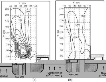
requirement for MILD combustion is oxygen dilution in the oxidant stream and for the mixture temperature to be above the self-ignition for the fuel. The oxygen dilution and the heating of the oxidizer can be achieved by the use of exhaust gas recirculation (EGR) (Katsuki & Hasegawa, 1998; Yusaf, Noor, & Wandel, 2013). The hot EGR will dilute the oxygen in the oxidant and preheat it. The oxygen content in the fresh air will reduce the dependence on the ratio of the fresh air and EGR. A requirement of MILD combustion is to preheat a mixture and dilute the oxygen content in the oxidant. In order to achieve this condition, EGR was utilized. From comparison of the flame observation for conventional combustion with 21% oxygen (Figure 1(a)) and MILD combustion (Figure 1(c)) with 2% oxygen (Gupta, Bolz, & Hasegawa, 1999), the flame can hardly be seen when the oxygen level is 2%. The temperature distribution was more homogeneous and this characteristic gives it an advantage over MILD combustion for many applications that need stable and distributed temperature throughout the combustion chamber.
[image:2.595.127.481.285.438.2](a) (b) (c)
Figure 1. Combustion air temperature of 1100°C and percentage of O2 concentration: (a) 21% oxygen, (b) 8% oxygen, (c) 2% oxygen (Gupta et al., 1999)
The basic combustion process must be balanced as shown in Equation (1). The balanced combustion process will not produce unburned hydrocarbon (UHC) in the exhaust gas. This shows that the combustion process consumes all the fuel. The combustion process can be written in a general hydrocarbon stoichiometric combustion equation:
( ) ( ) ( ) (1)
The stoichiometric combustion equation without EGR for low calorific value gas consists of 50% methane, 20% hydrogen and 30% carbon dioxide by volume (Noor et al., 2012b).
( ) ( )
( ) (2)
In a more general form, the combustion equation without EGR is
( ) ( )( )
664
where i, j and k are the mole fraction of the methane, hydrogen and carbon dioxide respectively. For lean combustion, we take the equivalent ratio, ϕ = 0.5 and the fuel composition is i = 0.5, j = 0.2 and k = 0.3:
( ) ( )
(4)
For rich combustion, we take the equivalent ratio, ϕ = 1.5 and the fuel composition is i = 0.5, j = 0.2 and k = 0.3:
( ) ( )
(5)
and the combustion equation with EGR is
( ) ( )( )
( ) ( ) ( )
( ) ( ) ( ) ( ) ] (6)
where λ is the EGR ratio. As stated above, the stoichiometric combustion equation for low calorific value gas consists of 50% methane, 20% hydrogen and 30% carbon dioxide by volume. If λ is 3.0, then 75% of the flue gas will flow back to the chamber and lower the oxygen level in the oxidizer stream. For this composition at stoichiometric condition,
ϕ = 1.0, the balance equation is
( ) ( )
( ) ( ) (7)
For lean combustion, the excess oxygen and nitrogen will not be involved in combustion and exhaust through the flue gas. These excesses can be seen in an example (Equation 8) of ϕ = 0.5, and 33% EGR, when the balance equation is
( ) ( )
(8)
In the rich combustion process, as there is not enough oxygen to burn a high mass fraction of CH4, excess methane and hydrogen will not be involved in combustion and will become unburned hydrocarbons. These conditions can be seen in an example (Equation 9) of ϕ = 1.5, and 66% EGR, when the balance equation is
( ) ( )
(9)
If the fuel is biogas with only methane and carbon dioxide, the general form of the combustion equation with EGR is
665
( ) ( ) ] (10)
The development of a MILD burner for non-premixed open flame was discussed. The burner was designed using ANSYS Fluent 14.5 to numerically simulate and predict the behavior of combustion and flame. The burner was then built at the USQ mechanical workshop. Methane, biogas and coal seam gas (CSG) will be used in the testing and experimental work. In order to design the combustion chamber, the basics of the combustion equation must be used to calculate the air fuel ratio (AFR). The study of the AFR using computational fluid dynamics was done to design the air and fuel inlet diameters and volume flow rates (Noor, Wandel, & Yusaf, 2012b).
CFD SIMULATIONS
The application of computer simulation techniques to improve many complex processes, including the combustion process, has rapidly expanded over the last decade. CFD is an important design tool that has been extensively used to explore and design engineering hardware (Baukal, Gershtein, & Li, 2001; Davidson, 2002) including combustion chambers. Moreover, computational simulation frequently provides information on physical quantities that are difficult to measure. CFD is increasingly being used for the optimization of gas burners (Scharler & Obernberger, 2000) and industrial gas furnaces (Dally, Riesmeier, & Peters, 2004; Noor et al., 2013a; Riahi, Mergheni, Sautet, & Nasrallah, 2012) or coal combustion (Calchetti, Nardo, Mongibello, & Mongiello, 2007). In this study, the CFD was used to model MILD combustion in the mode of non-premixed combustion. The second order scheme was used to discretize the governing equations, including mass, momentum, energy and species in addition to the turbulence transport and combustion model. The realizable
k−ε turbulence model (Shih, Liou, Shabbir, Yang, & Zhu, 1995) [that was developed
666
makes it easier for the exhaust gas to flow into the EGR pipe. The outlet for the exhaust was also lowered to assist the exhaust gas flow into the EGR inlet.
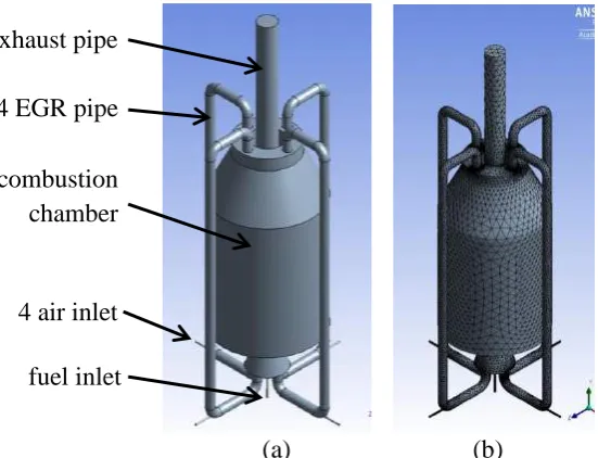
The small EGR pipe only allows a small volume of exhaust gas to flow downward. In order to increase the volume of the exhaust gas flow, the whole diameter of the EGR pipe was increased from 25 mm to 50 mm. To assist the EGR flow downward, a fresh air inlet was installed on the side of each EGR (Figure 2(a)). The purpose of this design is also to ensure that the exhaust gas mixes properly before entering the combustion chamber. Nakamura, Smart, and Van de Kamp (1993) and (Weber, Orsino, Lallemant, & Verlann, 2000; Weber, Smart, & Kamp, 2005) experimentally studied pilot-scale furnaces equipped with heat exchangers and demonstrated that heat transfer was affected by the port locations and angles. After finalizing the pre-design, the simulation was done on the final model (Figure 2) for the ignition location study (Noor et al., 2013a), air fuel ratio study (Noor et al., 2012b) and other parametric studies (Noor et al., 2012c) on the MILD combustion using biogas as a fuel. Different combinations of air and fuel compositions injected into the chamber gave different results.
[image:5.595.123.399.318.529.2]
(a) (b)
Figure 2. Final design with bigger EGR pipe: (a) schematic diagram with boundary condition; (b) model after meshing
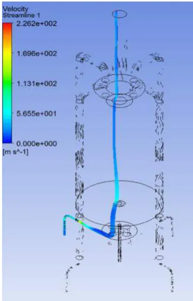
Figure 3 shows the velocity magnitude inside the combustion chamber. This flow shows that the chamber is open and that the chamber is at atmospheric pressure since the chamber is open on the top. This open chamber is considered to be an open combustion furnace. Figure 3 shows that the exhaust gas mainly flows out through the top opening and some of the exhaust gas flows through the EGR pipe as required. This result is in accordance with earlier research (Figure 4) that shows the main stream of the exhaust flowing out through the top exhaust pipe. Figure 5 shows the mole fraction of methane between 0 and 0.6 (Figure 5(a)) and between 0 and 0.05 (Figure 5(b)). This condition shows that all the methane was consumed by combustion and that almost zero unburned hydrocarbon will be released through the exhaust gas and EGR pipe. This happens when the combustion is reaching a stoichiometric condition with a lambda ratio of 1.0.
combustion chamber exhaust pipe
4 air inlet 4 EGR pipe
667
[image:6.595.181.429.85.398.2]
Figure 3. Velocity magnitude inside the combustion chamber
[image:6.595.201.392.443.740.2]668
[image:7.595.93.505.83.362.2](a) (b)
Figure 5. Mole fraction of CH4 species (a) between 0 and 0.6 (b) between 0 and 0.05
(a) (b)
[image:7.595.112.485.419.709.2]669
The homogeneous temperature of MILD combustion is presented in Figure 6, comparing the temperature contour for conventional combustion (Figure 6(a)) with room temperature oxidant at 21% oxygen mole fraction, and MILD combustion (Figure 6(b)) with preheated oxidant at 4% (lower) oxygen mole fraction (Tsuji et al., 2003). The temperature distribution for conventional combustion is between 100K and 1100K, which is a 91% difference from the lowest to the highest temperature, which is not a homogeneous temperature. The temperature distribution for conventional combustion is between 1000K and 1300K, which is a 23% difference from the lowest to the highest temperature, which is a homogeneous temperature. In this study, with the oxygen level from 3 to 13% before it is mixed with fuel, MILD combustion will be achieved (Figure 7(b)). Otherwise, combustion is not achieved in the MILD state (Figure 7(a)) (Noor et al., 2012a).
[image:8.595.89.509.263.543.2]
(a) (b)
Figure 7. MILD combustion state: (a) not achieved; (b) achieved
MODEL FABRICATION
670
[image:9.595.105.495.83.347.2](a) (b)
Figure 8. MILD burner setup: (a) with three glass windows; (b) gas control panel
671
[image:10.595.111.491.93.612.2](a) (b)
672
Figure 10. Schematic diagrams of combustion chamber: (a) ignition rod location; (b) location plan view; and (c) side view of ignition location and installation
(a) (b)
Figure 11. Ignition system: (a) ignition lead top view (inside the burner); (b) bottom view (outside the burner)
HEAT RELEASE RATE
[image:11.595.112.481.478.631.2]673
is 7.85 x 10⁻⁵ m2. The gas is injected into the combustion chamber at a maximum rate of 25.0 liter/min. This is equal to 4.16 x 10⁻⁴ m3/s. The fuel injection speed is 5.3 m/s. The mass flow rate depends on the density of the fluid. The density of methane gas is 0.668 kg/m3 (at 293K and 101.325 kPa), so the mass flow rate is 2.78 x 10⁻⁴ kg/s, which is gas density times volume flow rate. The heat release by the combustion of methane can be calculated by using the methane heating value (55.0 MJ/kg). The heat release is 15.3 kW, which is the mass flow rate times the gas heating value. The heat release rate or furnace power for the furnace at 25 liter/minute of methane volume flow rate is 15.3 kW. The methane thermal properties include internal energy (u), enthalpy, (h), specific heat (Cp), and heating value (hv). The heating value unit is J/mole or Joule/kg, used to measure the maximum amount of heat that can be generated by combustion with air at 25°C and 101.325 kPa. The highest heating value is hydrogen, which is 141.8 kJ/kg, while methane is 55.5 kJ/kg, the highest among the hydrocarbon fuels.
TEMPERATURE SENSORS AND DATA COLLECTION
Thermocouples were installed at 35 different locations on the combustion chambers such as the main chamber, air inlet, EGR and exhaust pipe. The computer used for data recording is equipped with a National Instrument (NI) data acquisition system and LabVIEW software. The temperature was measured using R-type and K-type thermocouples which were connected to an NI connector box. The measurement was displayed and recorded in a LabVIEW graphical user interface (GUI) and can be recorded and displayed in the format of an MS Excel spreadsheet. In this experiment, the National Instruments Data Acquisition (NIDAQ) system was used to measure and display the temperature measurement through thermocouples. LabVIEW software was used to manage and store the data collected. It consists of a chassis NIDAQ 9178 with a number of signal conditioning amplifiers and analog to digital conversion modules. Gas analyzers were used to measure the gas composition in the combustion chamber, EGR pipe and exhaust ducting. The analysis of gas composition is very important when evaluating NOx emissions, unburned hydrocarbon (UHC) and excess oxygen in the exhaust gas.
CONCLUSIONS
674
gas analyzers. The furnace power calculated for the 25 liter/minute of methane is 15.3 kW.
ACKNOWLEDGMENTS
The authors would like to thank the University of Southern Queensland (USQ), Ministry of Higher Education, Malaysia (MOHE) and Universiti Malaysia Pahang (UMP) for providing financial support and laboratory facilities. The first author also thanks A.A. Hairuddin (UPM), C. Galligan and B. Aston (USQ Mechanical Workshop) and Dr. Paul Baker (USQ combustion laboratory) for the discussions.
REFERENCES
Baukal, C. E., Gershtein, V. Y., & Li, X. (2001). Computational fluid dynamics in
industrial combustion. Boca Raton, Florida: CRC Press.
Calchetti, G., Nardo, A. D., Mongibello, G., & Mongiello, C. (2007). Mild combustion
simulation of coal water slurry. Paper presented at the Italian Section of the
Combustion Institute 30th Meeting on Combustion, Ischia, Italy.
Cavaliere, A., & de Joannon, M. (2004). Mild combustion. Progress in Energy and
Combustion Science, 30(4), 329-366.
Choi, C. E., & Baek, S. W. (1996). Numerical analysis of a spray combustion with nongray radiation using weighted sum of gray gases model. Combustion Science
and Technology, 115(4-6), 297-315.
Chui, E. H., & Raithby, G. D. (1993). Computation of radiant heat transfer on a non-orthogonal mesh using the finite-volume method. Numerical Heat Transfer, Part
B: Fundamentals, 23(3), 269-288.
Dally, B. B., Karpetis, A. N., & Barlow, R. S. (2002). Structure of turbulent non-premixed jet flames in a diluted hot coflow. Proceedings of the Combustion
Institute, 29(1), 1147-1154.
Dally, B. B., Riesmeier, E., & Peters, N. (2004). Effect of fuel mixture on moderate and intense low oxygen dilution combustion. Combustion and Flame, 137(4), 418-431.
Davidson, D. L. (2002). The role of computational fluid dynamics in process industries.
The Bridge, 32(4), 9-14.
EIA. (2011). Annual energy review Technical report DOE/EIA-0484. Washington DC, United States: Energy Information Administration, US Department of Energy Ghoniem, A. F. (2011). Needs, resources and climate change: Clean and efficient
conversion technologies. Progress in Energy and Combustion Science, 37, 15-51.
Gupta, A. K., Bolz, S., & Hasegawa, T. (1999). Effect of air preheat temperature and oxygen concentration on flame structure and emission. Journal of Energy
Resources Technology, 121, 209-216.
Hottel, H. C., & Sarofim, A. F. (1967). Radiative transfer. New York: McGraw Hill. Katsuki, M., & Hasegawa, T. (1998). The science and technology of combustion in
highly preheated air. Paper presented at the Proceedings of Combustion
Institute.
675
Li, P. F., Mi, J., Dally, B. B., Craig, R. A., & Wang, P. F. (2011). Premixed moderate or intense low-oxygen dilution (mild) combustion from a single jet burner in a lab-scale furnace. Energy Fuels, 25, 2782-2793.
Liu, F., Becker, H. A., & Bindar, Y. (1998). A comprehensive study of radiative heat transfer modelling in gas fire furnace using the simple gray gas and the weight sum of gray gas models. International Journal of Heat and Mass Transfer, 41, 3357-3371.
Maczulak, A. (2010). Renewable energy, sources and methods Facts on File. New York.
Mancini, M., Schwoppe, P., Weber, R., & Orsino, S. (2007). On mathematical modelling of flameless combustion. Combustion and Flame, 150(1-2), 54-59. Mastorakos, E. (2009). Ignition of turbulent non-premixed flames. Progress in Energy
and Combustion Science, 35, 57-97.
Merci, B., Naud, B., & Roekaerts, D. (2007). Impact of turbulent flow and mean mixture fraction results on mixing model behaviour in transported scalar pdf simulations of turbulent non-premixed bluff body flames flow. Turbulence and
Combustion, 79, 41-53.
Nakamura, T., Smart, J. P., & Van de Kamp, W. L. (1993). Combustion and emissions
control. Cardiff, UK: Institute of Energy.
Neophytou, A., Richardson, E. S., & Mastorakos, E. (2012). Spark ignition of turbulent recirculating non-premixed gas and spray flames: A model for predicting ignition probability. Combustion and Flame, 159, 1503-1522.
Noor, M. M., Wandel, A. P., & Yusaf, T. (2012a). A review of mild combustion and open furnace design consideration. International Journal of Automotive and
Mechanical Engineering, 6, 730-754.
Noor, M. M., Wandel, A. P., & Yusaf, T. (2012b). The modelling of the effect of air fuel
ratio on unburned hydrocarbons for mild combustion. Paper presented at the 2nd
Malaysian Postgraduate Conference, Bond University, Gold Coast, Australia. Noor, M. M., Wandel, A. P., & Yusaf, T. (2012c). A preliminary study of control
parameters for open furnace mild combustion using cfd. Paper presented at the
2nd Malaysian Postgraduate Conference, Bond University, Australia.
Noor, M. M., Wandel, A. P., & Yusaf, T. (2013a). The analysis of recirculation zone
and ignition position of non-premixed bluff-body for biogas mild combustion.
Paper presented at the 2nd International Conference of Mechanical Engineering Research, Gambang, Malaysia.
Noor, M. M., Wandel, A. P., & Yusaf, T. (2013b). Detail guide for cfd on the
simulation of biogas combustion in bluff-body mild burner. Paper presented at
the 2nd International Conference of Mechanical Engineering Research, Gambang, Malaysia.
Orsino, S., Weber, R., & Bollettini, U. (2001). Numerical simulation of combustion of natural gas with high temperature air. Combustion Science & Technology, 170(1), 1-34.
Parente, A., Galletti, C., & Tognotti, L. (2011). A simplified approach for predicting no
formation in mild combustion of ch4/h2 mixtures. Paper presented at the
Proceedings of the Combustion Institute.
Peters, N. (2000). Turbulent combustion: Cambridge University Press. Pope, S. B. (2000). Turbulent flows: Cambridge University Press.
676
Riahi, Z., Mergheni, M. A., Sautet, J. C., & Nasrallah, S. B. (2012). Numerical study of turbulent normal diffusion flame ch4-air stabilized by coaxial burner. Thermal
Science, 1, 1-20.
Scharler, R., & Obernberger, I. (2000). Numerical modelling of biomass grate furnace. Paper presented at the European Conference on Industrial Furnaces and Boilers (INFUB), Porto, Portugal.
Shih, T. H., Liou, W. W., Shabbir, A., Yang, Z., & Zhu, J. (1995). A new k−ε eddy
-viscosity model for high reynolds number turbulent flows-model development and validation. Computers and Fluids, 24(3), 227-238.
Smith, S. T., & Fox, R. O. (2007). A term-by-term direct numerical simulation validation study of the multi environment conditional pdf model for turbulent reacting flows. Physics of Fluids, 19, 85-102.
Szegö, G. G., Dally, B. B., & Christo, F. C. (2011). Investigation of the mixing patterns
inside a mild combustion furnace based on cfd modelling. Paper presented at the
Proceedings of the Australian Combustion Symposium, University of Newcastle, Australia.
Triantafyllidis, A., Mastorakos, E., & Eggels, R. L. G. M. (2009). Large eddy simulations of forced ignition of a non-premixed bluff-body methane flame with conditional moment closure. Combustion & Flame, 156, 2328-2345.
Tsuji, H., Gupta, A. K., & Hasegawa, T. (2003). High temperature air combustion. Boca Raton, Florida: CRC Press.
Weber, R., Orsino, S., Lallemant, N., & Verlann, A. (2000). Combustion of natural gas
with high-temperature air and large quantities of flue gas. Paper presented at the
Proceedings of the Combustion Institute.
Weber, R., Smart, J. P., & Kamp, W. V. D. (2005). On the mild combustion of gaseous,
liquid, and solid fuels in high temperature preheated air. Paper presented at the
Proceedings of the Combustion Institute.
Wünning, J. (1991). Flammenlose oxidation von brennstoff mit hochvorgewärmter luft.
Chem.-Ing.-Tech, 63(12), 1243-1245.
Yusaf, T., Noor, M. M., & Wandel, A. P. (2013). Mild combustion: The future for lean
and clean combustion. Paper presented at the 2nd International Conference of
Mechanical Engineering Research, Gambang, Malaysia.
NOMENCLATURES
CFD Computational fluid dynamics CO2 Carbon dioxide
EGR Exhaust gas recirculation GHG Greenhouse gas
IEA International Energy Agency LCV Low calorific value
NOx Nitrogen oxides