Rochester Institute of Technology
RIT Scholar Works
Theses Thesis/Dissertation Collections
2006
Assisted GPS solution in cellular networks
Gidon LissaiFollow this and additional works at:http://scholarworks.rit.edu/theses
This Thesis is brought to you for free and open access by the Thesis/Dissertation Collections at RIT Scholar Works. It has been accepted for inclusion in Theses by an authorized administrator of RIT Scholar Works. For more information, please [email protected].
Recommended Citation
Rochester Institute of Technology
College of
Applied Science & Technology
Assisted GPS Solution in Cellular Networks
By
Gidon Lissai
Thesis submitted in partial fulfillment of the requirements for thedegree of Master of
Science in Telecommunications Engineering Technology
Gidon Lissai Thesis approved by:
________________________________________________________________________
Professor Ronald G. Fulle (Chairman of the Thesis Committee)
________________________________________________________________________ Dr. Warren L. G. Koontz (TET Program Chair)
________________________________________________________________________ Dr. Chance M. Glenn Sr.
________________________________________________________________________ Professor Mark J. Indelicato
Table of Content
[image:4.612.98.525.229.562.2]Table of Figures ... 6
Table of Pictures ... 8
Acknowledgments... 9
Objectives... 10
Chapter 1 – Global Positioning System... 12
1.1. History of the GPS System ... 13
1.1.1. Transit, Timation, Secor, and 621B... 13
1.1.2. Implementation and testing... 16
1.1.3. Activation of the GPS system... 20
1.2. How does GPS work? ... 22
1.2.1. Satellite orbits... 22
1.2.2. Trilateration ... 23
1.2.3. Measuring distance from a satellite ... 26
1.2.3.1. Pseudo Random Code (PRC) ... 27
1.2.3.2. C/A and P-Code ... 27
1.2.3.3. Runtime measurement of the satellites’ signals ... 29
1.2.3.4. Data transmission from the satellites... 30
1.2.4. Timing synchronization... 32
1.2.5. Satellite positions... 33
1.2.5.1. Control Segment ... 33
1.2.5.2. System data ... 34
1.2.5.2.1. Clock Correction... 34
1.2.5.2.2. Ephemeris data... 35
1.2.5.2.3. Almanac data ... 35
1.2.6. Errors in the GPS system... 36
1.2.6.1. Signal’s velocity... 37
1.2.6.2. Multipath error ... 37
1.2.6.3. GDOP... 38
1.2.6.4. Doppler shift ... 38
1.2.7. User segment ... 40
1.2.8. Differential GPS ... 42
References – chapter 1 ... 43
Chapter 2 – Wireless Enhanced 911 ... 45
2.1. Regulation history of the Wireless E911 ... 46
2.2. Technical description of the 911/E911 systems... 49
2.2.1. Wireline E911... 50
2.2.2. Wireless E911 – phase I ... 52
2.2.3. Wireless E911 – phase II ... 54
2.3. Location solutions for E911 phases ... 55
2.3.1. Phase I location solution... 55
2.3.3. Network-based solutions ... 57
2.3.3.1. U-TDOA ... 58
2.3.3.2. Network-based solution - Pros and cons ... 60
2.3.4. Handset-based solutions ... 61
2.3.4.1. E-OTD (Enhanced Observed Time Difference)... 61
2.3.4.2. AFLT - Advanced Forward Link Trilateration ... 63
2.3.4.3. A-GPS – Assisted Global Positioning System ... 63
2.3.4.4. Hybrid solutions... 65
2.3.5. Tier I carriers - chosen solutions for phase II ... 66
References – chapter 2 ... 69
Chapter 3 – Assisted GPS technology ... 71
3.1. GPS receiver limitations ... 72
3.1.1. Time to first fix... 72
3.1.2. Weak signals... 74
3.2. A-GPS solution ... 75
3.2.1. A-GPS concept ... 75
3.2.2. A-GPS and the receiver limitations ... 76
3.2.2.1. Doppler shift ... 76
3.2.2.2. Integration period... 80
3.2.2.3. Other assisted parameters... 83
3.2.3. UE-based and UE-assisted solutions ... 83
3.2.4. Control Plane and User Plane ... 86
3.2.4.1. Control Plane... 86
3.2.4.2. User Plane ... 88
3.3. A-GPS deployment ... 90
3.3.1. Tier I carriers status ... 90
3.3.2. A-GPS providers... 91
References – chapter 3 ... 93
Chapter 4 – Integrating location-based applications to cellular networks... 95
4.1. Location based applications for cellular devices ... 96
4.2. Integrating location-based application to the cellular network ... 97
4.2.1. Using the MPC for location based application ... 98
4.2.1.1. Mobile Location Protocol ... 100
4.2.1.2. Pros and Cons... 101
4.2.2. Location based services that are offered by Verizon Wireless ... 102
4.2.2.1. Pros and Cons... 104
References – chapter 4 ... 105
Conclusions ... 106
Appendixes ... 108
Appendix A – Current Block II/IIA/IIR/IIR-M satellites ... 109
Appendix B – Block II/IIA/IIR/IIR-M individual satellite status ... 111
Appendix D – How time synchronization works ... 115
Appendix E – Almanac data ... 118
Appendix F – U-TDOA operation ... 121
Appendix G – Position Determination Data Message in CDMA and CDMA2000 networks 123
Table of Figures
Chapter 1
Figure 1.1 - Orbits of the GPS satellites ... 23
Figure 1.2 - Schematic illustration of distances intersection ... 24
Figure 1.3 - Three spheres intersection... 25
Figure 1.4 - Spheres intersection ... 26
Figure 1.5 - Cross correlation example... 30
Figure 1.6 - Composition of signals from GPS satellites... 31
Figure 1.7 - Position of the monitor stations ... 33
Figure 1.8 - Structure of one data frame... 36
Figure 1.9 - Example for Doppler shift calculation ... 39
Figure 1.10 - General Block diagram of the GPS receive ... 41
Chapter 2 Figure 2.1 - 9-1-1 call in a wireline E911 system... 52
Figure 2.2 - 9-1-1 call flow in wireless E911 Phase I system (NCAS Solution)... 53
Figure 2.3 - 9-1-1 call flow in a wireless E911 Phase II system (NCAS Solution)... 55
Figure 2.4 - E-OTD principle ... 62
Figure 2.5 - A-GPS concept ... 65
Chapter 3 Figure 3.1 - Structure of A-GPS... 76
Figure 3.2 - Frequency/Delay search space... 77
Figure 3.3 - Frequency/Delay search space and correlation peak... 78
Figure 3.4 - Frequency/Delay space with aiding information ... 79
Figure 3.5 - Frequency/Delay space with aiding information ... 79
Figure 3.6 - Non-coherent integration period Vs. RF power (in dBW)... 82
Figure 3.7 - The control plane solution in GSM network... 87
Figure 3.8 - The user plane solution in GSM network ... 89
Chapter 4 Figure 4.1 – Wireless E911 phase II network... 98
Appendixes
Figure C.1 - Code phase assignments... 113
Figure C.2 - C/A code Generation... 114
Figure D.1 - True location ... 115
Figure D.2 - False location ... 116
Figure D.3 - Extra measurement... 116
Figure D.4 - Time correction... 117
Figure F.1 - U-TDOA operation... 121
Figure H.1 - User plane architecture in CDMA network... 126
Table of Pictures
Picture 1.1 - ‘Timation 1’ satellite... 15
Picture 1.2 - Thor-Agena vehicle. ... 15
Picture 1.3 - GPS Block I satellite... 17
Picture 1.4 - Delta Rocket Launches ... 18
Acknowledgments
First, I would like to thank Professor Ron Fulle for supporting, guiding, understanding,
suggesting, encouraging, and being open minded.
I would also like to thank Professor Warren Koontz who made the master degree a dream
that came true.
In addition, I would like to thank Chris Angelucci, Ben Chen, and Roy Mira from
Verizon Wireless for their time and patience.
Last but not least I would like to thank my wife Adi, who once again redefined the term
Objectives
The ‘Wireless Enhanced 911’ rules, which were issued in 1996, state that the position of
a mobile device should be sent to Public Safety Answering Point (‘PSAP’) once a 9-1-1
call takes place from it. The rules imposed the cellular carriers to integrate a technology
into their networks so that the mobile device location can be transferred once a 9-1-1 call
is made. One of the chosen technologies was the Global Positioning System (GPS). The
solution suggests integrating a GPS receiver into every cellular device. But the GPS
receiver, as a stand alone solution, has some major performance limitations in regards to
the Wireless Enhanced 911 requirements.
The Assisted GPS (A-GPS) technology improves the GPS receiver performances. It
reduces the time it takes the receiver to calculate its location. It also enhances the
receiver’s reception sensitivity and improves the calculated position accuracy. With the
A-GPS technology, the GPS receiver solution becomes compatible with the rules
requirements. Two of the four large wireless carriers in the U.S. had chosen the A-GPS as
their location solution in their networks.
The A-GPS technology became an important part of the cellular industry. The intention
of the thesis is to explore the A-GPS solution and to show its necessity in today’s
GPS-based solutions. The following aspects are reviewed in the thesis – how the A-GPS
solution works, how it improves the GPS receiver performances, the technology that is
Another A-GPS related aspect that is reviewed in the thesis is the integration of
location-based applications in cellular networks. The location-location-based applications service is a new
The Global Positioning System (GPS) is a satellite-based navigation system. The satellite
network has twenty four dedicated satellites that broadcast signals towards earth. Those
signals enable the GPS receiver to calculate its three dimensional location (latitude,
longitude, and altitude) at any place in the world. The GPS position calculation is based
on measuring the distance from the GPS receiver position to the precise locations of the
GPS satellites.
1.1. History of the GPS System
The GPS system was developed by the United State Department of Defense (DoD) in
order to meet military requirements. But even before the system was operational, it was
already opened for civilian use. This chapter presents an overview of the GPS system
development from its beginning to the present day.
1.1.1. Transit, Timation, Secor, and 621B
Beginning in the early 1960’s, the DoD was looking for a global navigation system that
would be continuously available and would allow a wide spectrum of users to get
location information. The global solution requirement was also to be highly accurate so
that every possible user will be able to know where he/she is. The U.S. Navy and Air
Force began studying the concept of using radio signals transmitted from satellites for
satellite programs, which became the building blocks for the Global Positioning System1.
The U.S. Army also worked on its own solution.
The U.S. Navy came up with two different navigation systems – Transit and Timation.
Transit was the first operational navigation system based on information from satellites.
It provided two dimensional positioning and required long observation time before the
location was determined. The position was determined by the Doppler shift of the
received satellite signal. It was used by the Navy to locate maritime vehicles, ballistic
missiles, etc. Transit demonstrated that worldwide accurate navigation was possible from
space. Its operational constellation of satellites in circular polar orbits is still in use
today2.
The Timation system based its location calculation on timing information that came from
the satellites. This approach is also implemented in the GPS solution. The Timation
system provided two-dimensional position (latitude and longitude). It was based on two
experimental satellites that were launched at 1967 and 1969 (See pictures 1.1 and 1.2).
The U.S. Air Force designed and implemented the 621B system. The system provided
continuous service and three dimensional positioning. Its satellite signal (for ranging
purposes) was based on pseudorandom signal (PRN).
The U.S. Army presented the SECOR (sequential correlation of range) system: Each
SECOR satellite was linked to four ground stations — three at geographical points where
coordinates were to be to be pinpointed. Radio waves were sent from the ground stations
to the satellite and returned by a transponder. The position of the satellite at any time was
fixed by the measured ranges from the three known stations. Using these precisely
established positions as a base, ranges from the satellite to the unknown station were used
to compute the position of the unknown station3.
Picture 1.1 - ‘Timation 1’ satellite. Launched on May 31, 19672.
Picture 1.2 - Thor-Agena vehicle (the name of the orbital launch vehicle)2. The satellite
was launched into a 500 nautical mile polar orbit.
By the late 1960s, the U.S. Navy, Air Force, and Army were each working independently
on radio navigation systems that would provide all-weather, 24-hour coverage and
accuracies that would enhance the military capabilities of their respective forces1. In 1973
the Deputy Secretary of Defense decided to merge the proposed solutions to a single
satellite navigation system. By the end of that year, the DoD approved to proceed with
the development of the proposed system. The system, which named NAVSTAR Global
Positioning System (NAVSTAR GPS), was based on the 621B and Timation solutions.
1.1.2. Implementation and testing
The GPS system divides into three segments: Space segment – the satellites constellation
in space and their orbital planes. Full constellation has 24 satellites, which are placed in
six orbit planes (four per each); Control Segment – stations on earth that track the GPS
satellites and provides them with periodic updates; User Segment – the GPS receiver that
calculate its user location.
During the years 1974-1979 the GPS plan was tested. The space segment was tested at
the beginning with two refurbished Timation satellites. In 1977, user segment tests were
performed. Transmitters were installed on the earth’s surface in order to simulate the
satellites’ role in the GPS system. The final segment of GPS—a prototype ground control
In 1978 the first GPS satellite was launched and tested. The first group of satellites was
from Block 1 type (Usually marked as ‘Block I’. See picture 1.3). From 1978 to 1985 11
Block I satellites were launched from California, each having a weight of 845 kg. None
of those still operates today. Their lifespan was supposed to be 4.5 years and all of them
exceeded this lifespan by about another 5 years4. The Block I satellites were used to
demonstrate and test the feasibility of the GPS system.
Picture 1.3 - GPS Block I satellite5
The GPS program was initially designed to have 24 satellites. Due to a decision to have
major cuts in the FY81-FY86 budget, the program was restructured to have only 18
satellites. Block II satellites (the next satellites generation) development was dropped.
In 1983 a civilian airplane of the Korean Airline was shot down by the Soviet Union. The
reason was that the plane (flight 007) had gone lost over Soviet territory. Following the
incidence, the United State President, Reagan, offered to open the GPS service (free of
charge) for civilian aircraft use. This marked the beginning of the spread of GPS from
Another setback for the GPS program was the accident of the space shuttle ‘Challenger’
in 1986. The Challenger was planned to be the launching vehicle for the second
generation GPS satellites (Block II). Due to the shuttle loss, the satellites launching
schedule was delayed two years. The replacements for the shuttle were the Delta II
rockets, which were intended for transportation in the first place (See picture 1.4).
Picture 1.4 - Delta Rocket Launches6
In February 1989 the first Block II satellite was launched. It became operational a few
months later. Up to October 1990, nine satellites of block II were launched to space.
Block II satellites were designed to provide 14 days of operation without contact from the
control Segment7. They also had automatic detection of certain error conditions and anti
spoofing capabilities. Selective Availability (SA) was another feature which was
intentionally degrade the information that arrive from the satellites. SA was used to
protect the security interests of the U.S. and its allies by globally denying the full
accuracy of the civil system to potential adversaries8.
Block IIA (the ‘A’ stands for ‘advanced’. See picture 1.5) satellite had major
improvement: it can operate up to 180 days without contact from the control segment. An
additional improvement in the second generation satellites was the accuracy of the clocks
the satellites used. Accuracy is a necessary requirement for the GPS system. The location
calculation is time based and it is mandatory for the satellites clocks to be accurate and
not to go out of synchronization very often (See section 2 in this chapter - ‘How does
GPS work?’). Block II and Block IIA satellites are equipped with two rubidium and two
cesium atomic clocks with a clock stability of at least 10 - 13 seconds4. The design life
time of the Block II/IIA satellite is 7.3 years. The Block IIAs satellites were launched
from November 1990 through November 1997.
The Block IIR (the ‘R’ stands for ‘Replenishment’) model was the satellite’s generation
that followed the Block IIA satellites. They can work 180 days without contacting the
control segment. But unlike the Block II, they maintain full accuracy during that time
using a technique of ranging and communication between the other Block IIR satellites.
The next generation, Block IIF satellite, is planned to provide a second frequency for
civil use, allowing position determinations with even higher precision. These Block IIF
satellites will be equipped with hydrogen maser clocks instead of atomic clocks due to
their even higher precision. However these satellites will only be available some time
the GPS system. For example they are equipped with sensors capable of detecting atomic
explosions4.
For more information about the launches of Block II/IIA/IIR satellites see Appendix A.
Appendix B contains additional information about currently activated satellites.
Picture 1.5 - Block IIA satellite9
1.1.3. Activation of the GPS system
The SA (selective availability) of the satellites was deactivated during the Gulf War
(1990-1991). The purpose of it was to allow all the allied forces to use the GPS
technology. It was the first time that the GPS was used under combat conditions. The
GPS usage during the war was successful and proved to be operational. At the end of the
In September 1991 the United States offered to make the GPS available to international
and civil usage as soon as the system becomes operational. The offer promised free of
charge usage of the GPS system for at least 10 years. The following year, the United
States extended the offer for the foreseeable future and also pledged to provide at least
six years notice prior to termination of GPS operations or elimination of the GPS SPS
(Standard Positioning Service)1.
On December 8, 1993 the Initial Operational Capability (IOC) of the GPS system was
announced. The system was no longer considered as under development and was capable
of providing location with 100 meters accuracy.
On July 17, 1995 Full Operational Capability (FOC) was announced by the Air Force.
Full Operational Capability status means that the system meets all the requirements
specified in a variety of formal performance and requirements documents10.
On May 1, 2000 the use of SA (Selective Availability) was discontinued by the order of
the President of the United States. The immediate result was a major improvement in the
GPS receivers’ accuracy - from 100 meters to around 20 meters.
The GPS management from the beginning has been under the responsibility of the DoD.
A join task force to the DoD and the DoT (Department of Transportation) was established
in 1993 due to the future increase in civil use of the GPS. One of the JTF
recommendations was to have civil participation in managing and developing the GPS
In September 2005, President Bush updated the nation’s Global Positioning System
policy. The new policy gives the DoT authority equal to that of the DoD on the
committee that manages GPS technology and spectrum. The change in governance
reflects the fact that GPS is now used in more civilian applications than military ones11.
The revisions in the policy update military and homeland security roles for GPS and
designate it as a component of the critical infrastructure.
1.2. How does GPS work?
The GPS receiver uses the signals from the satellites in order to calculate its location. It
measures the distance from the satellites using the travel time of their radio signals. To
measure the travel time, the GPS system needs timing synchronization. Knowing the
distance from the satellites is not enough, the receiver also needs to know exactly where
the satellites are in space.
1.2.1. Satellite orbits
The GPS satellites network design requires twenty four satellites in order to achieve a
complete coverage all over the world. Currently there are twenty eight functioning GPS
satellites in the sky (See Appendix B). Twenty four of them are the primary satellites,
The GPS satellites orbit the earth over a period of 12 hours (speed of 800 meters per
second). The height of the satellites is around 20,200 km from earth (10,900
nautical-miles). The satellites orbit the earth at a speed of 3.9 km per second and have a
circulation time of 12 h sidereal time, corresponding to 11 h 58 min earth time. This
means that the same satellite reaches a certain position about 4 minutes earlier each day12.
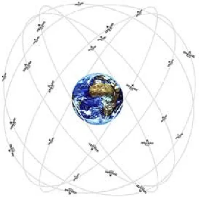
The satellites are arranged in six planes. Each plane has four slots so four satellites can be
arrange equidistantly within it. The arrangement guaranties that the signals of at least four
satellites can be received at any time all over the world. The planes have a 55 degree
[image:24.612.91.294.376.577.2]inclination angle towards the equator. Figure 1.1 shows the orbits of the GPS satellites.
Figure 1.1 - Orbits of the GPS satellites12
1.2.2. Trilateration
The GPS system is based on the trilateration concept. The trilateration concept states that
that you know their exact locations. The intersection of the distances from the references
to you is your location. The GPS system uses destinations from satellites as the distances.
Similar concept is triangulation. Triangulation uses angle measurements, together with at
least one known distance, to calculate the subject’s location. Occasionally people tend to
confuse between the two concepts. However, trilateration is the concept the GPS system
is based on.
An example of two dimensional trilateration (which gives a two dimensional location)
can be: The given data is that your location is 238 miles from Cleveland, OH, 339 miles
from Boston, MA, and 250 miles from New York, NY. Given the fact that you know the
exact locations of those cities, your location is Rochester, NY. Figure 1.2 schematically
shows the distances intersection.
Figure 1.2 - Schematic illustration of distances intersection
Rochester
Boston
Cleveland
The GPS receiver calculates a three dimensional location (latitude, longitude, and
altitude). The calculated distance between the GPS receiver and a satellite is the radius of
a sphere that the satellite is its center. Calculating the current location is done by figuring
out where the spheres intersect. Getting location information from three satellites leads to
two points in space where the spheres intersect (See figure 1.3). In order to decide which
one is the true location, a fourth measurement should be made. Usually one of the points
is too far from earth and therefore can be eliminated.
Figure 1.3 - Three spheres intersection13
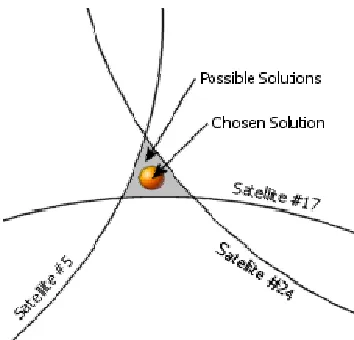
A fourth measurement is still necessary due to the nature of the spheres intersection -
Ideally, these spheres would intersect at exactly one point, causing there to be only one
possible solution to the current location, but in reality, the intersection forms more of an
oddly-shaped area. The GPS receiver could be located within any point in the area,
forcing receivers to choose from many possibilities14. Figure 1.4 shows the area that can
be created from three satellites. The calculated location in the figure can be any point in
the grey-colored area. More information about the GPS accuracy can be found in section
Figure 1.4 - Spheres intersection14
1.2.3. Measuring distance from a satellite
In order to calculate the distance of a GPS receiver from a satellite, we use the simple
equation: Velocity x Time = Distance. As mentioned before, the satellites broadcast
signals that can be received and analyzed by the GPS receivers. The velocity of an
electromagnetic ray in space is the speed of light (approximately 299,792.5 kilometers
per second/186,200,000 miles per second). Hence, the missing parameter for the distance
calculation is the time it takes the signal to travel from the satellite to the receiver.
The travel time measurement is achieved by timing the signal. It works in the following
way: the satellite begins transmitting a digital pattern (Pseudo Random Code – see
section 1.2.3.1) at a particular time. At the same exact time the receiver begins running an
identical digital code. When the signal arrives to the receiver, its pattern will lag behind
1.2.3.1. Pseudo Random Code (PRC)
The pseudo random codes (often called ‘pseudo random noise’ (PRN) or ‘pseudo noise’
(PN)) are the signals the satellites send. Each satellite has a different PRC so the GPS
receiver can differentiate between them. It means that each satellite is defined by its code.
The selected codes that are sent from the satellites are ‘Gold codes’. Gold codes have the
characteristic of a weak cross correlation among each other. The GPS receiver can then
have low interference when it tries to correlate with one of the satellites signals. The gold
codes also guarantee that the receiver won't accidentally pick up another satellite's signal.
Hence all the satellites can use the same frequency without jamming each other. The gold
codes make it more difficult for a hostile force to jam the GPS system. In fact the Pseudo
Random Code gives the DoD a way to control access to the system15.
There are 32 PRCs in the GPS system. The GPS receiver has all the satellites’ PRCs in its
memory so it can search for signals from all of them.
1.2.3.2. C/A and P-Code
Two different codes are sent from the GPS satellites, C/A (coarse acquisition) code and P
code (The ‘P’ stands for ‘precise’). The C/A code is used for civil GPS receivers. The P
code is for military use. Information about the C/A code generation can be found in
The C/A code is a 1023 “chip” long code, being transmitted with a frequency of
1.023 MHz. A “chip” is the same as a “bit”, and is described by the numbers “one” or
“zero”. The name “chip” is used instead of “bit” because no information is carried by the
signal16. 1023 chip long code with a frequency of 1.023MHz means that every 1msec the
PRC is repeated (1023/1.023M = 1msec) and that 1,023,000 chips are generated in a
second from the satellite. If we divide the number of chips per second by the velocity
(speed of light) we can see that the length of one chip can be calculated as 300 meters.
The timing measurement is done according to the delay of the pseudo random code from
the satellite. The delay is measured with how many chips are needed to be shifted in the
receiver’s code in order to correlate with the satellite’s code. Since one chip is equal to
300 meters, we can get distance accuracy of 300 meters. This is not a good accuracy. The
GPS receiver is much more precise. Modern GPS receivers are capable of calculating the
signal shift as precise as 1 % of one chip. Therefore the distance to the satellite can be
calculated with a precision of 3 m17. Additional information on runtime measurements
can be found in section 1.2.3.3.
Designed for military users, the P-code is a week-long pseudorandom number (PRN)
sequence, approximately 6*1012 bits long, with a bandwidth of 10.23 MHz. The long
length of the code makes it hard to acquire and difficult to spoof. The P-code is more
accurate than the civilian code and is more difficult to jam because of its wider
bandwidth. To ensure that unauthorized users do not acquire the P-code, the United
The P-code with AS, designated as the ‘Y-code’, is available only for users with the
correct deciphering chips18.
1.2.3.3. Runtime measurement of the satellites’ signals
As previously mentioned, each satellite transmits PRC that is known to the GPS receiver.
The algorithm that is used to calculate the difference between the satellite’s PRC to the
receiver’s PRC is cross correlation. In signal processing, the cross-correlation (or
sometimes "cross-covariance") is a measure of similarity of two signals, commonly used
to find features in an unknown signal by comparing it to a known one. It is a function of
the relative time between the signals. For discrete functions fi and gi the cross-correlation
is defined as
The sum is over the appropriate values of the integer j and an asterisk indicates the
complex conjugate19.
Figure 1.5 demonstrates cross correlation: The two signals in the two upper rows are
multiplied with each other. The lowest row is the result of the multiplication. The sum of
the signal in the result row, is the cross correlation of the two signals. The green pulse
represents the beginning of the signal. If we shift the upper row three chips to the left, the
Figure 1.5 - Cross correlation example17
There is a clear maximum value when the two signals are correlated. This is how the GPS
receiver knows that the timing measurement is done and that the number of ‘shifts’ that
were made until then is the number of chips that indicates the time.
1.2.3.4. Data transmission from the satellites
The data from the satellites is modulated onto a carrier signal before it transmitted. The
carrier frequency has some constrains:
• Frequencies above 2 GHz require beam antennae for signal reception.
• For frequency ranges below 100 MHz and above 10 GHz, there are large Ionospheric
delays.
• The speed of propagation of electromagnetic waves with low frequencies in media
like air deviates from the speed of light (in vacuum). For low frequencies the runtime
measurement is falsified16.
• The PRCs require a high bandwidth. The C/A signal, for example, requires a 20 MHz
bandwidth.
The chosen frequencies, one for C/A code and the other for P-code, are marked as L1 and
L2. The L1 band transmits both the C/A and P-codes at a frequency of 1575.42 MHz; the
L2 band transmits the P-code only at a frequency of 1227.6 MHz18. The signals are
modulated using the binary phase shift keying (BPSK) modulation scheme.
Figure 1.6 shows the composition of signals that are transmitted from the satellites.
Explanation about the ‘navigation system data’ channel can be found in section 1.2.5.2.
The ‘Modulo 2 Sum’ is equivalent to the XOR Boolean operation (0+0=0; 0+1=1;
1+0=1; 1+1=0).
1.2.4. Timing synchronization
Timing synchronization is a crucial point in the GPS system. The system is based on
measuring the travel time of a radio signal. Therefore, the satellites’ clock and the
receiver’s clock must be synchronized.
Satellites use atomic clocks for timing. Atomic clocks are very precise clocks that
consider keeping time better than any other clock. Each satellite has four atomic clocks.
The clocks types that are in use are Cesium and Rubidium. Atomic clocks are very
expensive ($50K to $100K). That fact excludes them from being integrated into the GPS
receivers. This would make the receiver non-affordable technology for the average
customer.
Standard quartz clocks are used for timing on the GPS receivers. The way to keep the
receiver’s clock synchronized with the satellites’ clock is to constantly reset it according
to timing measurements from the satellites. For this operation, the receiver must get
pseudo random codes from at least four satellites.
The receiver uses the measurement from the fourth satellite in order to find the ‘correct
time’. The four (or more) location measurements from the satellites can intersect only at
one point. The times that are used in order to calculate the point are based on one ‘current
time’. This time value is the one the satellites use. The receiver resets itself to this time.
The result of this ongoing procedure is that the GPS receiver presents atomic clock
1.2.5. Satellite positions
Due to the time synchronization, the GPS receiver can calculate its exact distance from
the satellites it receives signals from. But in order to use the distances for trilateration, the
[image:34.612.87.395.269.415.2]receiver must know exactly where the satellites are.
Figure 1.7 - Position of the monitor stations20
1.2.5.1. Control Segment
The Department of Defense stations on earth, which monitor the GPS satellites 24 hours
a day, are called the control segment. The five stations (See figure 1.7 for their locations
in the world) check the satellite’s position, speed, and altitude. Errors can also be
detected in the satellites’ orbits. These errors are caused by gravitational pulls from the
moon and sun and by the pressure of solar radiation on the satellites21. On the control
information is also called ‘ephemeris’. The data transmission, which includes other
information than the ephemeris, occurs once or twice a day.
1.2.5.2. System data
In order for the GPS receiver to know exactly where the satellites are, the information
that is sent from the control segment, must find its way to it. This is done by the system
data signal.
A 50 Hz signal, which contains satellite status, clock correction, satellite orbits, and
additional information, is constantly transmitted from each satellite. From this data
stream the GPS receiver gets mandatory parameters like date, time, and of course the
satellite’s position.
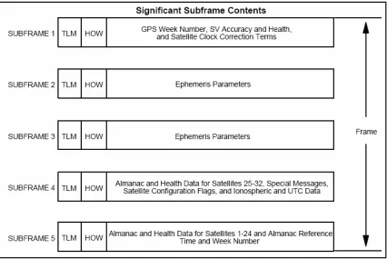
The transmission rate of the signal is 50 bits per second. The complete data signal
consists of 37,500 bits which means it takes 12.5 minutes to get the complete signal. The
signal is divided into 25 frames of 1500 bit (interval of 30 seconds for transmission).
Each frame has 5 sub frames, 300 bits each: clock correction data information (sub frame
1), ephemeris data (sub frames 2 and 3), and support data (sub frames 4 and 5). Figure
1.8 shows the frame structure.
1.2.5.2.1. Clock Correction
The GPS receiver works according to GPS reference time. The satellites’ clocks are not
synchronized with that time. In order to know the exact time the PRC was transmitted in
field. The receiver corrects the time received from the satellite with the equation (in
seconds)
t = t
sv– (
∆
t
sv)
L1 wheret = GPS system time (seconds),
tsv = effective SV PRN code phase time at message transmission time (seconds),
(∆ tsv)L1 = SV PRN code phase time offset (seconds)22.
SV stands for ‘Space Vehicle’, which is a common alias for the GPS satellite.
1.2.5.2.2. Ephemeris data
From the ephemeris parameters on sub frame 2 and 3, the GPS receiver can calculate the
current position of the satellite from which it obtained the data signal. The ephemeris
data also gives detailed instructions on where the satellite will be in the next few hours.
Therefore, a set of ephemeris data is valid for several hours.
1.2.5.2.3. Almanac data
Almanac data is part of the support data sub frames. The almanac is a subset of the clock
and ephemeris data, with reduced precision22. Unlike the ephemeris sub frame, which
includes information only from the sending satellite, the almanac includes information on
every satellite in the GPS constellation. It allows the GPS receiver to view which
satellites are available for it. The GPS receiver can then correlates with the signals from
for a quick fix in location after the receiver is turned on. Appendix E explains more about
[image:37.612.96.522.196.481.2]the almanac parameters.
Figure 1.8 - Structure of one data frame22
1.2.6. Errors in the GPS system
In the GPS system, the most vulnerable component to errors is the signal that is
transmitted from the satellites. It is the GPS receiver’s task to take into account the
1.2.6.1. Signal’s velocity
When calculating the distance from the satellite, the velocity of the signal was estimated
to be the speed of light. But the speed of light is constant only in a vacuum. On the way
from space to earth, there are some atmospheres that cause propagation delays to the
signal. In other words, the signal’s velocity is different than the speed of light while it
crosses those atmospheres. The ionosphere is the layer of the atmosphere ranging in
altitude from 50 to 500 km. It consists largely of ionized particles which can exert a
perturbing effect on GPS signals. While much of the error induced by the ionosphere can
be removed through mathematical modeling, it is still one of the most significant error
sources23. The troposphere layer, which is closer to earth, also has an influence on the
signal propagation.
One way to minimize the errors is to predict the atmospheric delay of the GPS signal.
This approach is called ‘modeling’. A different approach is the ‘dual frequency’ that by
comparing the two carriers from the satellite (L1 and L2) the atmosphere influence can be
calculated.
1.2.6.2. Multipath error
Multipath error occurs when the antenna receives the same signal in two or more paths.
The error is caused when the signal is reflected from terrestrial objects, such as
mountains and buildings. The GPS receiver should ignore the other signals that are not
1.2.6.3. GDOP
GDOP, Geometric Dilution of Precision, happens when the satellites’ distance circles
(see figure 1.2), which define the receiver’s position, cross each other at a very shallow
angle. It occurs when the GPS receiver chooses satellites that are close to one another.
That increases the error margin around a position. If it picks satellites that are widely
separated the circles intersect at almost right angles and that minimizes the error region24.
It is up to the GPS receiver to pick the satellites that will cause the lowest GDOP.
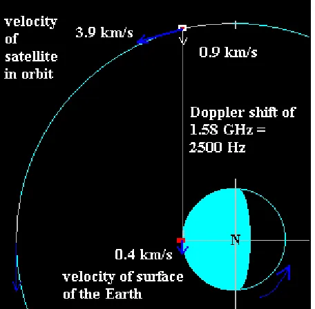
1.2.6.4. Doppler shift
Doppler shift is defined as the change in frequency of a wave caused by movement of the
source relative to the observer. The frequency increases when the source and observer
approach each other and decreases when they move apart. The source’s motion causes a
real shift in frequency of the wave. The observer’s motion results in only a small shift in
the frequency. Due to the constant movement of the satellites, the GPS signals arrive at
the GPS receiver with a different frequency/wavelength than the one they had when they
were transmitted. It requires the GPS receiver to search for the signal in different
frequencies than the carrier frequency. The frequency shift that the Doppler Effect creates
can be calculated. Taking into consideration the satellites’ velocity and the earth
movement, results in a range of frequency shift of ±4200 Hz. The maximum Doppler
Figure 1.9 shows an example of Doppler shift calculation. The equation is as follow: If
the moving source is emitting waves through a medium with an actual frequency f0, then
an observer stationary relative to the medium detects waves with a frequency f given by:
Where v is the speed of the waves in the medium and vs, r is the speed of the source with
respect to the medium (negative if moving towards the observer, positive if moving
[image:40.612.90.318.360.584.2]away), radial to the observer25.
Figure 1.9 - Example for Doppler shift calculation26
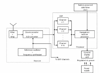
1.2.7. User segment
The user segment in the GPS system is the GPS receiver. Figure 1.10 presents a block
diagram of the multi-channel GPS receiver. The received signals are filtered,
pre-amplified and converted from analog to digital. Samples are then addressed to the digital
signal processor (DSP) section, which contains N parallel channels to simultaneously
track carriers and codes from N satellites. Each channel includes code and carrier
tracking loops to perform code and carrier phase measurements and demodulation of the
navigation message data27.
The code tracking loop measures the delay between the arriving PRC to the locally
generated PRC. In each channel in the DSP, the generated PRC, which related to a
selected satellite from the constellation, tries to lock on the correlation peak with the
arriving signal (See section 1.2.3.3). Thanks to the properties of the code sequences (C/A
code), the signals coming from satellites other than the one under consideration can be
discarded27. The loop sometimes uses a delay-lock loop (DLL) which delays the signal
until the two PRC codes are aligned. If the time result is multiplied by the speed of light
we will get the distance measurement, called pseudorange. However, the distance result
will be not accurate since it doesn’t take into account the propagation delays of the signal
and the clock synchronization between the satellite and the receiver.
The Carrier tracking loop uses phase-lock loop (PLL) in order to match the phases of the
the oscillator locks onto the satellite signal, it will continue to follow the variations in the
phase of the carrier as the range to the satellite changes18. The pseudo-delta-range
measurement is based on integrated carrier-phase measurements. It is an addition range to
the pseudorange which could not be detected from the PRCs, but from the phase
correction. The pseudorange, pseudo-delta-range, integrated Doppler (the measurement
of Doppler shift frequency of phase over time), together with the demodulated navigation
message, are sent to the navigation/receiver processor.
It can be concluded that there is a search over the possible code-delays and frequencies in
[image:42.612.93.437.413.669.2]order to acquire the GPS signal for a specific channel.
1.2.8. Differential GPS
Differential GPS (DGPS) was designed in order to improve the accuracy the GPS
receiver provides. The inaccuracy factors the DGPS deals with are the timing delays
caused by the atmospheres layers, multipath, and satellite and receiver clocks. It does it
through a nearby reference receiver that measures the timing error of all the satellites in
range and broadcasts the information to all the DGPS receivers in the area.
The DGPS relies on the fact that a satellite’s signal has the same timing delay for the
reference receiver and for all the other DGPS receivers that are a few hundreds miles
away. The reason for it is that the area is very small in relation to the travel distance of
the satellite’s signal. Therefore the timing delays are the same within that area.
The reference receiver calculates the timing delay by using ‘backwards’ calculation, i.e. it
uses its known position in order to calculate the timing delays. Since it knows its
location, it knows what the travel time of the signals should be. The timing error is the
difference between the arrived timing to what it should be.
The reference receiver broadcasts the message in a known frequency. The DGPS
receivers receive the message and handle the timing delay of the received GPS signals.
The only problem with the DGPS concept is that the reference receiver can work only for
each specific area and there need to be multiple reference receivers in order to cover a
References – chapter 1
1 Pace, S. ,Frost, G.P., Lachow, I., Frelinger, D., Fossum, D., Wassem, D., Pinto, M.M. (1996) The Global Positioning System: Assessing National Policies. Retrieved January 2, 2006 from
http://www.rand.org/publications/MR/MR614/MR614.appb.pdf
2Official US Navy web site. Timation and GPS Satellite History. Retrieved January 2, 2006 from
http://ncst-www.nrl.navy.mil/NCSTOrigin/Timation.html
3 David Darling. SECOR (Sequential Collation of Range). Retrieved January 2, 2006 from
http://www.daviddarling.info/encyclopedia/S/SECOR.html
4 Kowoma (December 1, 2005). The Setup of the GPS System. Retrieved January 2, 2006 from
http://www.kowoma.de/en/gps/satellites.htm
5 Mission and spacecraft library. GPS Block 1. Retrieved January 2, 2006 from
http://msl.jpl.nasa.gov/QuickLooks/gps1QL.html
6 Nemiroff. R. , Bonnell, J. (December 13, 1995). APOD: December 13, 1995 - A Delta Rocket Launches. Retrieved January 2, 2006 from http://apod.gsfc.nasa.gov/apod/image/delta_nasa_big.gif
7 UNITED STATES NAVAL OBSERVATORY (December 19, 2005). BLOCK II SATELLITE INFORMATION. Retrieved January 2, 2006 from ftp://tycho.usno.navy.mil/pub/gps/gpsb2.txt
8 Federal Aviation Administration, Satellite Navigation, Product Teams. GPS FAQS. Retrieved January 2, 2006 from http://gps.faa.gov/FAQ/faq-gps.htm#ad2
9Mission and spacecraft library. GPS Block 2 and 2A. Retrieved January 2, 2006 from
http://samadhi.jpl.nasa.gov/msl/QuickLooks/gps2QL.html
10 U.S Coast Guard, Navigation Center. (July 17,1995).GLOBAL POSITIONING SYSTEM FULLY OPERATIONAL Retrieved January 2, 2006 from http://www.navcen.uscg.gov/gps/geninfo/global.htm
11 Mosquera, M. (January 10, 2005).DOT to lead civilian GPS management. Retrieved January 2, 2006
fromhttp://www.gcn.com/24_1/inbrief/34755-1.html
12 Kowoma (December 1, 2005). Satellite Orbits. Retrieved January 2, 2006 from
http://www.kowoma.de/en/gps/orbits.htm
13 Trimble. Step1:Triangulating from satellites. Retrieved January 2, 2006 from
http://www.trimble.com/gps/triangulating3.html
14Person, J. (December 29, 2004). Writing Your Own GPS Applications: Part 2. Retrieved January 2, 2006 from
http://www.codeguru.com/Csharp/Csharp/cs_data/tutorials/article.php/c8875__3/
15 Trimble. Step 2: Measuring distance from a satellite. Retrieved January 2, 2006 from
http://www.trimble.com/gps/distance4.html
16 Kowoma (November 30, 2005). Transmitted GPS Signals. Retrieved January 2, 2006 from
http://www.kowoma.de/en/gps/signals.htm
17 Kowoma (December 1, 2005). Runtime Measurement of the Signals. Retrieved January 2, 2006 from
http://www.kowoma.de/en/gps/signals_runtime.htm
18 Pace, S. ,Frost, G.P., Lachow, I., Frelinger, D., Fossum, D., Wassem, D., Pinto, M.M. (1996) The Global Positioning System: Assessing National Policies. Retrieved January 2, 2006 from
http://www.rand.org/publications/MR/MR614/MR614.appa.pdf
19 Wikipedia (December 29, 2005). Cross-correlation. Retrieved January 2, 2006 from
http://en.wikipedia.org/wiki/Cross-correlation
20 Kowoma (December 1, 2005). Control Segment (Monitor Stations). Retrieved January 2, 2006 from
http://www.kowoma.de/en/gps/control_segment.htm
21 Trimble. Step 4:Knowing where a satellite is in space. Retrieved January 2, 2006 from
http://www.trimble.com/gps/positions3.html
22 GPS NAVSTAR, Global Positioning System. (June 2, 1995) GLOBAL POSITIONING SYSTEM STANDARD POSITIONING SERVICE SIGNAL SPECIFICATION, second edition. Retrieved January 2, 2006 from http://www.navcen.uscg.gov/pubs/gps/sigspec/gpssps1.pdf
23Trimble. Ionosphere. Retrieved January 2, 2006 from http://www.trimble.com/gps/ionosphere.html
24 Trimble. Step 5: Correcting errors. Retrieved January 2, 2006 from
http://www.trimble.com/gps/errors5.html
25 Wikipedia (February 26, 2006). Doppler effect. Retrieved March 4, 2006 from
http://en.wikipedia.org/wiki/Doppler_effect
26 Bogan, L. (December 18, 1998). Doppler Shift of Satellite Frequency Correction. Retrieved January 2, 2006 from http://www.go.ednet.ns.ca/~larry/gps/doppler.gif
The emergency phone number in the U.S. is 9-1-1. The Basic 911 phone system routes all
the 9-1-1 calls to a Public Safety Answering Point (‘PSAP’). PSAP is a facility that is
staffed and equipped to receive 9-1-1 calls. The Enhanced 911 (‘E911’) phone system
provides improved service to the 9-1-1 callers. When a person dials 9-1-1 from a landline
phone it guarantees the following: 1. the location of the caller will be transferred to the
PSAP; 2. the call will be routed to the relevant PSAP. It means that the PSAP, which has
responsibility for the area that the phone call comes from, will receive the call.
In the early nineties, when the usage of cellular devices increased, there was a concern
regarding wireless 9-1-1 calls. Unlike landline calls, which come from a set phone that its
location is known to the system, there is a problem to provide the caller’s location when
it comes from a cellular device. The wireless Enhanced 911 rules seek to apply the E911
actions to a 9-1-1 call that comes from a cellular device.
2.1. Regulation history of the Wireless E911
On June 12, 1996 the Federal Communications Commission (FCC) adopted a Report and
Order that creates rules to govern the availability of basic 911 services and the
implementation of Enhanced 911 (E911) for wireless services1. According to the rules,
the deployment of the E911 for wireless calls was divided into two phases. Phase I
required the wireless carriers to provide the PSAPs the location of the cell site that the
call was routed from, i.e. the cell the user that made the 9-1-1 call is physically in (See
number. Phase II states that the location of the mobile station must be provided to the
PSAP in two dimensions (latitude and longitude), with accuracy within a radius of 125
meters in 67 percent of all cases1.
Phase I was scheduled to begin on April 1st, 1998. Beginning at that date, PSAPs could
request from the wireless carriers to be compatible with the rules. Phase II was scheduled
to begin on October 1st, 2001.
The deployment schedule and the accuracy demands were changed by the commission on
October 6, 1999, when it published the ‘third report and order’. One of the reasons for the
changes was the development of handset-based location technology. Handset-based
solution means that the handset takes the measurements that are used for the location
calculation. On a network-based solution the measurements and the location calculation
are done by the network (more information about location solutions can be found in
section 2.3).
The new accuracy demands determined to be: For network-based solutions: 100 meters
for 67 percent of calls, 300 meters for 95 percent of calls; for handset-based solutions: 50
meters for 67 percent of calls, 150 meters for 95 percent of calls2.
The new schedule was divided into two:
• For handset-based solution - once a PSAP request is received for a Phase II
implementation, within six months of the request or by October 1, 2001,
o The wireless operator needs to ensure that 100 percent of all new mobile
stations activated are ALI-capable.
o The wireless operator needs to implement any necessary network upgrades
to ensure proper operation.
o The wireless operator needs to begin delivering to the PSAP the location
information that satisfies the Phase II requirements.
Within two years of the request or by December 31, 2004, whichever is later, the
wireless operator needs to strive for 100 percent penetration of ALI-capable
mobile stations in its total subscriber base3. The term ‘ALI-capable’ refers to the
mobile station ability to send the latitude and longitude location information to the
PSAP.
• For network-based solution – the FCC replaced its previous plan, which required
that implementation be fully accomplished within 6 months of a PSAP request,
with a revised rule requiring the carrier to deploy Phase II to 50 percent of callers
within 6 months of a PSAP request and to 100 percent of callers within 18 months
of such a request2.
The commission also directed the wireless carriers to report their plans for implementing
E911 Phase II, including the technology they plan to use to provide caller location, by
October 1, 20002.
In September 2000, the FCC made some adjustments to the rules. Two of them were
December 31, 2005, the date for carriers to reach full penetration of ALI-capable
handsets in their total subscriber bases. The second was to modify the operational
definition of full penetration from "reasonable efforts" to achieve 100 percent penetration
of ALI-capable handsets to a requirement that 95 percent of all handsets in a carrier's
total subscriber base be ALI-capable4.
On July 2002, the FCC reluctantly granted non-nationwide Tier II (mid-sized regional
carriers) and Tier III (small carriers) temporary, limited relief from the Phase II
implementation deadlines5. For the six nation wide carriers - AT&T Wireless, Cingular
Wireless, Nextel Communications, Sprint PCS, Verizon Wireless, and VoiceStream
Communications (called ‘T-mobile’ today) – the requirements stayed the same.
The E911 rules had more revisions over the years. Most of them were regarding Tier II
and III carriers. The main requirements stayed the same for the Tier I carriers.
One major addition to the E911 rules is the E911 requirement for IP-Enabled service
providers. The commission published an order on June 3rd, 2005 stating that it adopts
rules requiring providers of interconnected voice over Internet Protocol (VoIP) service to
supply enhanced 911 capabilities to their customers6.
The following section discusses the wireline and wireless E911 network configuration. It
shows how the 9-1-1 call is routed to the right PSAP and how the PSAP receives the
location information of the call.
2.2.1. Wireline E911
Wireline 911 system simply routes the 9-1-1 calls to a PSAP. The system has two major
limitations that were mentioned earlier: 1. the origin of the call is unknown; 2. the call is
not necessarily routes to the PSAP that served the geographic location of the caller. The
limitations make the 911 system inefficient and problematic: the operator cannot call
back the caller in case the 9-1-1 call was disconnected, valuable time is wasted on
collecting the caller’s location and identification, the call can be routed to the wrong
PSAP and it would take time for the appropriate forces to get details about the call. The
Wireline E911 system resolves the two limitations.
ANI (Automatic Number Identification) is a feature that identifies the telephone number
of the caller. The feature was introduced for billing purposes so that long distance calls
can be properly billed. The caller phone number is transferred through the signaling
network. ALI (Automatic Location Identification) is a database that contains a
subscriber’s name, address, and telephone number. In case the system has the caller’s
telephone number, this database can provide the address and name that is associated with
it. The ANI and ALI are utilized by the E911 system. The equipment at the PSAP –
over a separate data circuit7. When the E911 call is received at the PSAP, it uses the
calling number to send a query to the ALI. The ALI then returns the caller’s name and
address.
The Selective Routing is the functionality in the E911 system that routes the 9-1-1 calls
to the proper PSAP. The E911 Control Office is a tandem switch that is in charge of this
functionality (often called ‘Selective Router’). The 9-1-1 call is routed to the E911
Control Office from the Central Office. The E911 CO then uses the ANI information to
find the street address that associate with the phone number. For that action, the Selective
Router uses its own database. According to the address, the call is routed to the proper
PSAP.
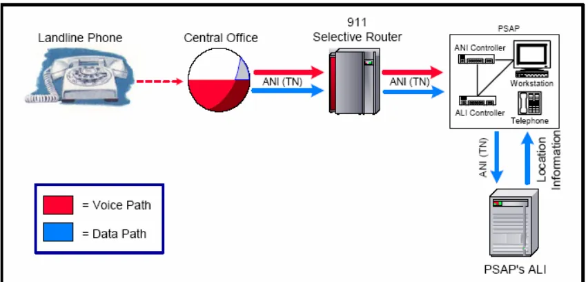
The following is a description of the 9-1-1 call flow in a wireline E911 system: a 9-1-1
call is placed from a wireline telephone and sent to the local central office that serves that
specific telephone. The central office recognizes the call as 9-1-1 and forwards the call to
a specialized switch, referred to as a selective router. The selective router routes both the
voice and the caller’s telephone number (ANI) to the appropriate PSAP. The PSAP’s
Customer Premise Equipment (CPE) uses the ANI to retrieve the caller’s Automatic
Location Information (ALI) by querying the ALI database8. Figure 2.1 shows the
Figure 2.1 - 9-1-1 call in a wireline E911 system8
2.2.2. Wireless E911 – phase I
The MSC (Mobile Switching Center) is the component in the wireless system that routes
the calls to and from the base stations. It bridges between the cellular network and other
networks (PSTN, internet, etc). So when there is a 9-1-1 call from a cellular device, it is
routed from the base station to the MSC.
In the NCAS* solution, the MSC has dedicated pseudo telephone numbers (also called
Emergency Service Routing Key (ESRK)) per each cell. When a MSC receives a 9-1-1
call, a processor associated with the switch knows the cell site/sector where the call is
* There are several phase 1 solutions which are implemented today: Call-path Associated Signaling (CAS),
coming from and selects an unused pseudo telephone number from the set associated
with the cell site/sector7. In some networks, the processor that picks the ESRK can be the
MPC (Mobile positioning Center). The processor (or MPC) is also in charge of ‘pushing’
the ESRK, callback number, and location information to the ALI database. The ‘pushing’
is done through a separate data link. The call is forwarded from the MSC to the Selective
Router with the pseudo telephone number. The Selective Router Data Base contains
information that associates the pseudo telephone number (and its associated cell
site/sector) with a particular PSAP7. It finds the proper PSAP the call should be routed to
and forwards the call with the pseudo telephone number. The PASP queries the ALI with
the pseudo telephone number and gets the call back number and the cell site that is
[image:54.612.96.518.432.645.2]associated with it. Figure 2.2 displays the call and information routing.
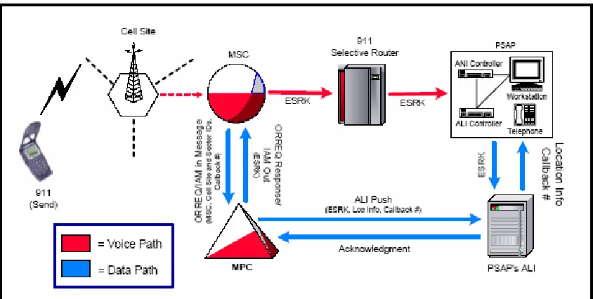
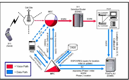
2.2.3. Wireless E911 – phase II
The flow of the 9-1-1 call in phase II is similar to the one in phase I, but because the
required location information is different (longitude and latitude) it becomes more
complicated to send it to the PSAP’s ALI. First, it may take more time to make the
necessary computations to locate the wireless caller than it does to transmit the voice data
to the PSAP. Second, the amount of information transmitted is greater. Finally, the
information may need to be refreshed one or more times to improve accuracy or to
maintain a continuous location on a moving caller (such as when the call is made from a
car)9.
Phase II implementation requires two additional components in the wireless network –
PDE and CRDB. The PDE (Position Determination Equipment) determines the location
of a wireless handset. As mentioned in section 2.1, there are two types of PDE
technologies - handset based and network based. The CRDB (Coordinate Routing Data
Base) receives the handset location from the MPC and returns the information necessary
to forward the call to the proper E911 Control Office8.
The call flow (NCAS solution*) uses the ESRK as an identifier for the call (similar to
phase I solution). The MPC sends the ESRK to the MSC, which sends it to the Selective
Router. Based on the ESRK, the SR forwards the call to the appropriate PSAP. The PSAP
then queries the ALI with the ESRK. The ALI queries the MPC for location. The MPC,
which gets the location information from the PDE, sends the caller’s latitude and
longitude to the ALI. The ALI forwards the information to the PSAP. The location
information of the caller can be refreshed during the call. The data link between the MPC
to the ALI, which is TCP/IP based, is used for this purpose. Figure 2.3 presents the call
[image:56.612.93.521.206.471.2]and information routing in wireless E911 phase II system.
Figure 2.3 - 9-1-1 call flow in a wireless E911 Phase II system (NCAS Solution)8
2.3. Location solutions for E911 phases
2.3.1. Phase I location solution
Wireless E911 Phase I required the wireless carriers to provide the cell site/sector
When a call is made from a cell phone (sometimes referred to as UE (User Equipment) or
MS (Mobile Station)), it communicates over wireless channels with a base station. The
base station is the cellular network component that is in charge of receiving the cell
phone signals and routes the calls to and from it. The area the base station is in charge of
in terms of network reception is called ‘cell’. The cellular network is built in a way that if
a cell phone is active, the network knows what base station is ‘in charge’ of it. It makes
the cellular carrier job very easy since the location information they are required to
provide is already known and available.
In phase I, there is a well known accuracy issue: the cell size is large (typically 2km to 20
km diameter) and there is no indication of exactly where the 9-1-1 caller is, in the cell. In
urban areas with a dense network of smaller cells the positioning is generally more
accurate than in rural areas where there are fewer base stations and the cells are large10.
Some cells are divided into areas called ‘sectors’. Information about the caller’s sector
location gives better indication about the caller’s location but still provides an area and
not exact location. The sector information can be transferred to the PSAP.
2.3.2. Phase II location solutions
Phase II location requirements forced the wireless carriers to come up with new
technological solutions and integrate them into their network and/or their cellular devices.
There are two approaches for phase II solution: network-based solution and
Network-based location solutions use location equipment within the network to
determine the location. Methods that use the network to provide location are TDOA
(Time Difference of Arrival), AOA (Angle of Arrival), TOA (Time of arrival), and
Multipath Analysis. More about the network based location solutions can be found in
section 2.3.3.
Handset-based location solutions use technology within the mobile handset to determine
the location. Usually, the solutions require network modification as well. Methods that
use the handset in order to provide location are A-GPS (Assisted GPS), AFLT (Advanced
Forward Link Trilateration), OTDOA (Observed Time Difference of Arrival), and
E-OTD (Enhanced Observed Time Difference). More about the network based location
solutions can be found in section 2.3.4.
Within the handset-based solutions there is also the hybrid approach. The approach
suggests combining the A-GPS method with another handset/network-based solution.
The motivation behind this approach is that each solution will compensate the other.
More information about hybrid solutions can be found on section 2.3.4.4.
2.3.3. Network-based solutions
In networked-based solutions the signals measurements and the location calculation are
done by the network.
The cellular device is capable of sending and receiving signals to and from other base
stations that are not ‘in charge’ of it. While it has primary connection to the cell’s base
nearby. The cellular network uses those communication channels to get information from
nearby cells. With this information it calculates the cell phone location. There are few
methods of how to calculate location using information from nearby base stations.
One, which is not very common, is Time of Arrival (TOA). In this method, the base
stations calculate the arrival time of the signal from the cell phone and pass it to the
network location server. The server needs at least three measurements in order to
determine the exact location (according to the trilateration concept). It means that three
base stations would need to be involved in the process and send the time measurement of
the cell phone.
A more common method is Angle of Arrival (AOA). With this method the server
requires only two measurements. The base stations measure the angle (or direction) of the
received signal from the cell-phone. The location server analyzes the measurements and
calculates the location.
2.3.3.1. U-TDOA
The network-based solution that some of the Tier I carriers decided to integrate into their
networks as phase II solution is U-TDOA (Uplink Time Difference of Arrival). The
solution can be integrated in to all types of cellular networks - GSM, GPRS, CDMA, and