Rochester Institute of Technology
RIT Scholar Works
Theses
Thesis/Dissertation Collections
2005
Development of Control Algorithm and a
Simulation Tool for Self-Assembly of Microsystems
Based on Swarm Technology
Siddharth Mestry
Follow this and additional works at:
http://scholarworks.rit.edu/theses
This Thesis is brought to you for free and open access by the Thesis/Dissertation Collections at RIT Scholar Works. It has been accepted for inclusion in Theses by an authorized administrator of RIT Scholar Works. For more information, please [email protected].
Recommended Citation
DEVELOPMENT OFCONTROL ALGORITHMAND A SIMULATION TOOL FOR
SELF-ASSEMBLYOF MICROSYSTEMS BASED ON SWARMTECHNOLOGY
A Thesis
Submittedinpartialfulfillmentofthe
Requirements forthedegreeof
MasterofScience in IndustrialEngineering
inthe
DepartmentofIndustrial & SystemsEngineering
Rochester InstituteofTechnology
by
SiddharthMestry
DEP ARTMENT OF INDUSTRIAL AND SYSTEMS ENGINEERING
KATE GLEASON COLLEGE OF ENGINEERING
ROCHESTER INSTITUTE OF TECHNOLOGY
ROCHESTER, NEW YORK
CERTIFICATE OF APPROVAL
M.S. DEGREE THESIS
The M.S. Degree Thesis of Siddharth Mestry
has been examined and approved by the
thesis committee as satisfactory for the
thesis requirement for the
Master of Science degree
Approved by:
James B. Taylor
Dr. James B. Taylor, Thesis Advisor
Title of thesis or dissertation:
D'i\J
£1's)fM£NJ
of.
cnbITRGL
AL~Q({rn-\
M
AND A
S\MDkA3)Ol\.' :n'!f)LFog
sEl£--
A-SSEM£>L'(
~£Name of author:
5' DOH A-R1\-\
1'1
E~ThYDegree:
_..L.M ....
S~·_ _
--::-_ _
--;;;-_~----_:__--- -Program: 'l:ND\)S,TQ.\ A\ .2..SYS1'FY\S
tNt,1 NE\-JS' N ~College:
\<-pOE
C~SON
C()\.l...E"'t.\.EC\f
ENY,\Na~.H.,~~
)
RrT
I understand that I must submit a print copy of my thesis or dissertation to the RIT Archives, per current RIT guidelines for the completion of my degree. I hereby grant to the Rochester Institute of Technology and its agents the non-exclusive license to archive and make accessible my thesis or dissertation in whole or in part in all forms of media in perpetuity. I retain all other ownership rights to the copyright of the thesis or dissertation. I also retain the right to use in future works (such as articles or books) all or part of this thesis or dissertation.
Print Reproduction Permission Granted:
I,
Siddharth Mestry
,
hereby grant permission to the Rochester Institute Technology to reproduce my print thesis or dissertation in whole or in part. Any reproduction will not be for commercial use or profit.Signature of Author: _--,S~i~d~d!.!..h!,!,:!a!.!..rt!:.!.h!...;M~e:..:!s~tr.J-Y
_ _ _ _ _ _ _ _
Date: _ _ __ _Print Reproduction Permission Denied:
I, ' hereby deny permission to the RIT Library of the
Rochester Institute of Technology to reproduce my print thesis or dissertation in whole or in part.
Signature of Author: _ _ _ _ _ _ _ _ _ _ _ _ _ _ _ _ _ _ Date: _ _ _ _ _
Inclusion in the RIT Digital Media Library Electronic Thesis & Dissertation (ETD) Archive
I, ' additionally grant to the Rochester Institute of Technology
Digital Media Library (RIT DML) the non-exclusive license to archive and provide electronic access to my thesis or dissertation in whole or in part in all forms of media in perpetuity.
I understand that my work, in addition to its bibliographic record and abstract, will be available to the world-wide community of scholars and researchers through the RIT DML. I retain all other ownership rights to the copyright of the thesis or dissertation. I also retain the right to use in future works (such as articles or books) all or part of this thesis or dissertation. I am aware that the Rochester Institute of Technology does not require registration of copyright for ETDs.
I hereby certify that, if appropriate, I have obtained and attached written permission statements from the owners of each third party copyrighted matter to be included in my thesis or dissertation. I certify that the version I submitted is the same as that approved by my committee.
-ABSTRACT
"Chunxel"
Technologyis anovel conceptofconstructing 3-dimensionalstructures using a
group of intelligent, autonomous, and cooperating micro robots. Chunxels are small roboticmodules, cubicalinshape, which areimmersedin atankcontaining a viscousfluid.
The chunxels arepropelledbythe electromagnetic forces createdbypassing directcurrent
throughasetoflarge coils placedoneachface ofthe tankand small coils embeddedinthe
micro device. The chunxels follow a set of rules which mimic a swarmbehavior and
self-assemble inthe liquidtoform a3-D structure. Swarmbehavior is adynamicproblem and
in order to ensure the completion of the task in reasonable time by the swarm it is
necessary to have a robust control algorithm and a navigation strategy. The objective of
this research was to develop such a control algorithm which when followedwould assure
the successful completion ofthe taskgivento thechunxels.Also inordertounderstandthe dynamics ofthe swarm and verify the control strategy it was important to simulate this
I thankDr. James B. Taylor, mythesis advisor, for his immensesupport duringthe course
ofthisresearch. Itwas a great experience workingunderhim. He hasbeen a greatmentor,
and aperson I will always lookupto forthe rest ofmy life. Thank youforyourpatience
andfor yourguidance not onlyrelatedto thisresearchbut alsoforthe smallbutimportant
thingsyouhavetaughtmeabout life.
Iwould especiallyliketo thankProf. Paul H. Stiebitzforgiving me anopportunitytowork
onthe chunxel project.His enthusiasm and his timelyadvice helped me tomake progress
inthisthesis, at crucial moments.
Thanks to Dr. Andres Carrano forkeeping immense faith in me atthe start ofmy Masters
Degree.
ThankstoDr. Alejandro Engel for hishelp duringthe initialstage ofthis thesis.
FinallyI wantto thank tomywife, and myparentsfortheirencouragement and supportin
CONTENTS
1. INTRODUCTION 1
2. BACKGROUND 3
3. TECHNICAL DETAILS OF THE CHUNXEL DEVICE 6
3.1. Externalcoilsdriving sequence 7
3.2. Robot assembly andconstruction 8
3.3. Results ofInitial Trial 9
4. STATEMENT OF PROBLEM 10
5. LITERATURE REVIEW 13
6. METHODOLOGY 18
6.1. Phase 1: Developmentof aTwo Dimensional Simulation Tool 20
6.1.1. Javaand2D Simulation Tool 20
6.1.2. Javacoordinate system&directionalconventions 21
6.1.3. Basic Control Algorithm 22
6.1.4. Collision Detection 25
6.1.5. Proportional Motion 28
6.2. Phase2: Demonstration ofSynergistic behavior using 2-D Simulation Tool 31
6.2. 1. Synergistic behavioralgorithm 3 1
6.2.2. Searchpath algorithm 34
6.2.3. Shortcomingsofthe search path algorithm 37
6.3. Phase 3: Developmentof aControl Algorithm and a3-D Simulation Tool 38
6.3.1. Introductionto Java3D 39
6.3.2. Forceequations 39
6.3.3. Animationanddisplacementofthechunxel 45
6.3.4. Proportional FeedbackMotion 47
6.3.5. Coasting 48
6.3.6. User interface 49
6.4. Phase 4: Verification of3-D Simulation Tool 51
6.4.4.
Coasting
Test 566.4.5. Cos-Factor Test 57
6.4.6. Proportional Test 58
6.5. Phase 5:Experimentation andOptimization
usingthe3-D Simulation Tool 62
6.5.1. DesignofExperiments: Experiment 1 63
6.5.2. Analysis I 64
6.5.3. DesignofExperiments: Experiment2 66
6.5.4. AnalysisII 66
7. CONCLUSIONS & FUTURE RESEARCH 69
7.1. Results & Conclusion 69
7.2. Future Research & Recommendations 70
REFERENCES 72
APPENDICES 76
Appendix A: 2D Simulation Flowchart 76
Appendix B: Screenshotof3D Simulation Tool 81
AppendixC: DateofForce Test 82
Appendix D: Screenshots ofCos Factor Test 92
Appendix E: DataofProportional Feedback Motion Test 93
Appendix F: Experiment 1 Data & Results 118
ListofTables
Table 1: 2DArrayfor storing Chunxel InformationinJava 24
Table2: Rules for Search PathAlgorithm 37
Table3: FactorsandLevels for Experiment I 63
Table 4: FactorsandLevels forExperiment2 66
Table5: Optimum ValuesoftheFactors from Response Optimizer 67
Table 6: Predicted Values for Response Variables 67
Table 7: 7l
RunConfiguration 67
Table8: Optimum Configuration 70
Table 9: Force Testdata 82
Table 10: Proportional Feedback Motion Test Data (withoutPFM) 93
Table 11: Proportional Feedback Motion Test Data (withPFM) 102
Table 12: 4 Factor-3 level, Full Factorial Design-Experiment 1 118
Figure 1: Chunxel Device
(Prototype)
4Figure2: CurrentGeneration Chunxels 5
Figure3: ControlDrivingSequence 7
Figure4: Timing Delay 8
Figure 5: Schematic Diagramofthe Chunxel 8
Figure 6: Javacoordinate system & ChunxelDimensions inJava 2D 22
Figure 7:BoundingBoxCollision Detection 27
Figure 8: Proportional Feedback Motionin2DSimulation Tool 29
Figure9: Block Diagramfor Generalflow of2DSimulationProgram 30
Figure 10: Figure 11 Figure 12: Figure 13: Figure 14: Figure 15: Figure 16:
Figure 1 7.
Figure 18. Figure 19: Figure 20: Figure 21: Figure 22: Figure 23: Figure 24: Figure 25: Figure 26. Figure 27. Figure 28: Figure 29:
2DSimulation ToolScreenshots 32
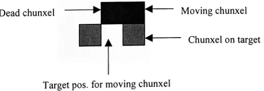
Dead Chunxel Retrievalfrom nearthe Tank Walls 33
Dead Chunxel RetrievalfromneartheBase ofthe Tank 33
MovingChunxel Trappedin One Direction 34
MovingChunxel Trappedin Two Directions 34
Sub-routineto Circumventan Obstaclein Y-axis(Step 1) 35
Sub-routineto Circumventan Obstaclein Y-axis(Step 2) 35
Sub-routineto Circumventan Obstacle in X-axis(Step 1) 36
Sub-routine to Circumventan ObstacleinX-axis (Step 2) 36
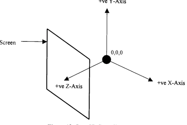
Java 3D Co-ordinate System 39
Calculation ofMagnetic Force ofAttraction 41
Calculation of Cosfactor 41
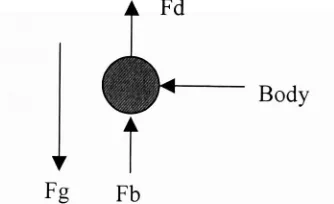
Forces actingonaBody CompletelySubmerged inaLiquid 44
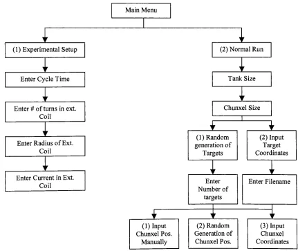
Relationshipof Time ON ofInternal CoilversusDistancefromthe Target 48 Block DiagramshowingtheStart-upOptionsfor3D Simulation Tool 50
Propulsion Forcev/sDistance fromtheCoil 54
Velocityv/sDistance from thecoil 55
Distance fromthe Coilv/sTime 56
Distance fromthe Coilv/sTime (withinfluenceofCoasting) 57
Time ONfortheInternal CoilwithoutProportionalFeedbackMotion 60
Figure 31: OscillationsoftheChunxelwithProportionalFeedbackMotion OFF 61 Figure 32: Oscillationsofthe ChunxelwithProportionalFeedback Motion ON 61
Figure 33: MainEffects Plotfor Response Time 64
Figure34: MainEffectsPlotfor Std. Deviation(Oscillations) 65
Figure35: 3DSimulation ToolScreenshot 81
Figure36:Screenshots ofthe Visual Observation Testfor Cos Factor Effect 92
Equation 1: Magnetic ForceofAttraction 40
Equation2: Cos Factor Equation 42
Equation3: DragForce 42
Equation4: Effective Propulsion Force 43
Equation5: BuoyantForce 44
Equation6:Net Forceon aSubmergedBody 44
Equation 7: Net Force on aSubmergedBodymoving intheDownward Direction 45
Equation8: NetForce on aSubmergedBody Movinginthe Upward Direction 45
Equation 9: Force actingon abodyinmotion 45
Equation 10:Acceleration ofthe Chunxel 45
Equation 11: Velocityofthe Chunxel 46
1. INTRODUCTION
Theneedtoquicklyconstructthree-dimensionalcolordisplays and objectsfrom computer-generated designs is extensive. Designers using personal computers or workstations
commonly emulate three-dimensional objects by using computer graphics software to
create sophisticated shading andcoloring schemes. RapidPrototyping technologies canbe employed to construct permanent three-dimensional objects by building shapes from specialized materials. Alternatively, specialized imaging techniques can quickly produce color stereoscopic images that are quite realistic, but these have no solid substance and often require a special viewingapparatus. The combination oftwo emerging technologies, swarms technology and Microsystems technology, offers a unique opportunity to quickly create color three-dimensional objects and displays. "Construction of three dimensional objects and displays using swarms of intelligent microsystems"
is a concept for a new
device based onemerging swarm and micro-systemtechnologies. This concept is referred
asthe"Chunxel Technology".
Swarm technology, following the social insect metaphor is concerned with the collective behavior of large number of intelligent autonomous agents, with limited capability to perceive, reason and act, that are capable ofperforming sophisticated tasks, such as food harvesting and nest building (Stiebitz P.H., Carrano A.L., Alejandro B.E., 2002). Swarm
research attempts to understand and mimic thisbehaviorof social insectsto come upwith alternative robotic solutions. Swarm engineering requires generation of swarm conditions and fabrication of a set ofbehaviors that satisfy the given swarm condition. This swarm
condition, whensatisfied, will guidethe generationof a swarm ofagents,which is capable ofcarrying outthe desiredactions. No specific method is formulated for the generation of swarm condition anditis largelyproblemdependent.
Microsystems technologies are those focused on the development ofhighly integrated
mechanical, electrical, optical, chemical, biological and computing systems whose
2002).
Integratingtheabove twotechnologiesgives riseto thechunxel technologythatconsistsof intelligent, autonomous, cooperating micro robots, known as chunxels, and a display housing,whichisacubicaltankcontainingaliquidcarrier mediainwhichthechunxels are
neutrally buoyant (Stiebitz P.H., Carrano A.L., Alejandro B.E., 2002). The chunxels can self-propel and selfnavigate through a viscous fluid. Within this environment, chunxels will be able to self-assemble to form different pre-defined three-dimensional shapes
(StiebitzP.H.,CarranoA.L.,Alejandro B.E.,2002).
This technology has numerous applications in the areas of three-dimensional real-time displays, rapid prototyping, entertainment special effects, games and toys. Other uses of the chunxels technology are in production of three-dimensional maps for military or exhibition purposes and 3D organs for medical training (Stiebitz P.H., Carrano A.L., Alejandro B.E., 2002).
Variouspossible fields of applicationhave beenmentionedforthisinvention. The chunxel technology has been conceptualized with rapid prototyping in mind. CAD files would be transferred to a control station, sending informationtochunxels. The chunxels wouldthen assembleintoa prototype oftheitem described inthe CADfiles.
An as yet unexplored area for chunxel research and application is that chunxels can be usednot onlyto generate static structuresbut also canbe usedto showdynamic behavior.
This dynamic behavior can be used in animating displays for advertising and also in entertainment industry. Another serious application of dynamic chunxel behavior is
2. BACKGROUND
In August 2001, an invention disclosure entitled "
Construction of three dimensional
objects and displays using swarms ofintelligent Microsystems" was filed withRochester Institute ofTechnology's office ofGrants, contracts and Intellectual Property. The work for this research, which was referredto as "Chunxel Technology"
was already initiated in
summer of2001 utilizing Kate Gleason College ofEngineering (KGCOE) research funds
granted to the Laboratory for Autonomous and Cooperative Microsystems (LACOMS). LACOMS is a multi-disciplinary research effort focused on the development and integrationof swarmtechnologieswithMicrosystemstechnologies.
Thewhole chunxel systemwillconsistofthefollowingmajor components:
A system ofintelligent, mobile, partiallyautonomous Microsystems (referredto as Chunxels)thatcan altertheircolor and self assembleintopre-defineddesired
three-dimensional color shapes.
A display housing containing liquid carrier media that provides buoyancy for the
chunxels.
Softwarethat translates standardCADfilesintochunxelassemblyinstructions.
Controlsoftwarethatco-ordinatestheassemblyof chunxels.
Acommunicationsystemthatallows a computerto send and receiveinformationto
andfromthechunxels.
Ameans to transfer energyto the chunxels (StiebitzP.H., CarranoA.L., Alejandro
B.E.,2002).
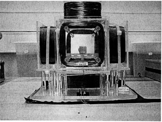
Chunxels are propelled by forces created by magnetic fields due to a set of large coils placed inthe environment and poweredbydirect current, and small coils embeddedinthe device also powered by direct current. Figure 1 shows the chunxeldevice prototype along
with a chunxel placed in the center of the tank. The display housing of the current prototype is a 6-inch cubical tank made of acrylic walls and surrounded by six external
proportionalto the radius, current,andnumberofwindings oftheexternalcoils, the radius, current and number ofwindings ofthe internalcoil,the distance betweenthe two coils and thepermeabilityoftheliquidmedium.
Figure 1: Chunxel Device(Prototype)
The development of working prototypes is envisioned to be in four stages. The first
generation chunxels are 25mm cubes. This chunxel has anovel six-sided shape with three out-dented and three in-dented surfaces that have been developed to promote the self-alignment ofthe groups (Stiebitz P.H. 2002). Eachside ofthe firstgeneration chunxels is manufactured by injection molding such that size identical pieces could be assembled in
any combination ofin-dents and out-dents. Figure 2 shows the current generation 25 mm chunxels. Each chunxel consists of a means for position sensing, a means for attaching itselfto other chunxels, and a communication system capable of sending and receiving informationfrom thesystem control and acomputing system(StiebitzP.H., Carrano A.L.,
Alejandro B.E., 2002). The second generationwill be 12mm cubes also manufactured by
conventional machining and molding techniques, while the third generation will begin
making the transition to MEMS (Micro Electro Mechanical
Systems)
fabricationtechniques reducing the size to 4 mm and finally shrinking it to 1mm in the fourth
Figure 2:CurrentGenerationChunxels
This section presents the hardware and the control details of the chunxel device. The
understandingofthehardware details ofthe chunxel andthe control system usedtopropel thechunxels inthe fluidenvironmentwillhelpin
discussing
thescope ofthisresearch.Eachchunxel hastwomajoroperational modes as follows:
The propulsionmode: theexternal andinternal coilswillbeused aselectromagnets; and
The positioningmode:theexternal coilswillbeused as a generator of magnetic field.
Propulsion:
For thepropulsion purpose, a48V DC power supply is used to generate a magnetic force
and drive the coil. Each external coil will have an intermittent DC signal. The chunxel
could then use one ofthe internal coils as an electromagnet to move along the magnetic
field created by the external coil. Power from the front or back coil gives a movement
along the x-direction, power from the west or east coil gives a ymovement and north and south a z movement.Thepowersupply isa48 VDCpowersupply(Yvanoff, Marie 2002).
Positioning:
Forthepositioningpurpose, anACpowersupply is usedto drivethecoil.This secondway to power the external coils will generate a time varying magnetic field inside the tank, whichinduces an emfintheinternalchunxel coils.Asthischunxel comes closerto thecoil powered, the emfinduced in the three internal coils increases. These coils are orthogonal and representtheX, YandZ-axis ofthechunxel(Yvanoff,Marie2002).
Communications betweena system controller andthe chunxels is achievedbythe pulsing the external coils in a structured fashion. By counting the induced emf pulses on the
chunxelcoil, a series of pulses canbe decodedto extract a message transmittedby ahost
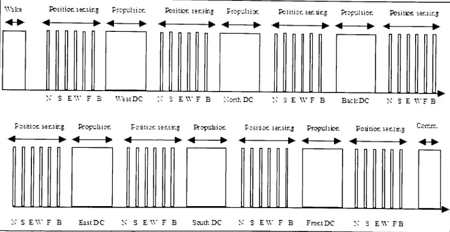
3.1. External coils
driving
sequenceTodrivethe six external coils,anAC andDC sequenceis used,theAC forthepositioning
sensingandthe DC for propulsion, asdescribed intheprevious
section. TheDC energizes the external coils in the sequence West, North, Back,
East, South, Forward. The three orthogonal coils within the chunxel are optionally energized in concert with the external coils to produce thrust sequentially in the six directions. In the second operational
mode, the chunxel's spatial position is determined by applying an alternating current to the external coilssequentially, and thensensingtheinduced emfinthe chunxel coils(power is
not applied to the chunxel coil in this mode). The control
driving
sequence andthe timedelays are shownin Figure3 andFigure4respectively (Yvanoff,Marie 2002).
fcfefce Portionsa^ir.s Propulsion Rasitien sansing Proptfiston Basiiiiffl searing Propulsion Fositcr.sosae
->
*--+> <- -*- -+- -*-
<-K S EV.'
F B VSfestI>C :: S BWF E NwthDC N S E W F E EickDC N S E WF B
Positionsensing fteputeunn Posttkai sensing RrapuUior. PosHtun sensing Propulsion P-oatior. sensing Cemsm.
-?-- ? --
-+--* ? A-
->-*< >
<-EV.'
F E Ei-tDC N S BW F E Sooth DC N S EV.'
[image:19.525.50.502.285.518.2]F B FfCT.tDC EV." FB
< ? A ?
??
KXtoS
lWms
A >* ?- ?
[image:20.525.100.430.466.608.2]U 15 IS
Figure 4:Timing Delay
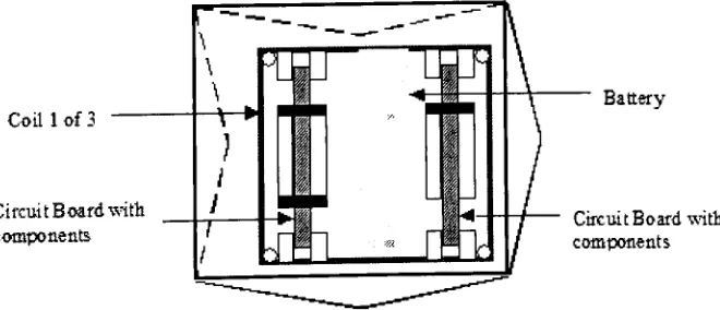
3.2. Robot assemblyand construction
Inside the chunxel, two 19mmsquares of single layercircuitboardsandbatteriesconstitute
the electrical components. Oneofthebatteries is usedto drive the internalcoils whenthey
are used as electromagnets. Two other batteries are used to supply current to a micro
controller and signal amplifiers. Eachofthree indented facesofthe cube containsthe three smallinternal coils while the two out-dentedfacescontainthe circuitboards andthe small
batteries, and on the third one there is abattery used to drive the coils. Design detail and
constructionofthechunxelsisshownin Figure 5.(Yvanoff,Marie2002)
Coil 1of3
Circuit Boardwith
components
Battery
Circuit Boardwith
components
3.3. Results ofInitial Trial
The initial trial ofthe chunxel device was conducted in March/August 2002. The goal of
this demonstrationwas fora proofofconceptforthe chunxel device. It turnedoutthat the
chunxelswere
behaving
as expected. Some ofthe observations thatwere madeduringthisrunare asfollows:
The wakeupsignal wakedupthechunxels;
Thechunxeltimingscheme was synchronizedwiththe drivingsequence;
Thespeedofthechunxels
during
thepropulsion was as expected;Thechunxel seemedtomovearoundthe targetareabutneverstopped; and
One ofthechunxel locatednearthecorner ofthe tankspun around.
As it turned out, the concept of chunxel device was working properly and provedthat it
4. STATEMENT OF PROBLEM
In chunxel technology the behavior ofthe chunxel is primarily based on the concept of
swarms. Swarm engineering has two formal steps. The first involves the generation of a
swarm condition. Swarm condition is a set of rules or behaviors, which the individual
agents in the swarm must follow in order to form a co-operative structure within the
swarm. This isa conditionwhich,when satisfied, will guidethe generation of a swarm of
agents which is capable ofcarrying out the desired action or actions. The second step in
swarmengineeringinvolvesthefabricationof abehavioror set ofbehaviorsthatsatisfythe
given swarm condition. Alsothe generation of swarm behavior is adynamicproblem and
in order to ensure the completion of the task in reasonable time by the swarm, it is
imperativetodevelopa robust navigation strategy.
The collective behaviors of components ina dynamic system (like a swarmbehavior) can
influence the environment and when this occurs the constraints on the components in a
system are not fixed, and thus attempts to analyze the system, must provide an ongoing
mutable parameterization ofthe environment(A Tutorial IntroductiontoSwarm). Thus, in
order to understand the dynamics ofthe swarm system under a given navigation strategy
and test the performance of the algorithm it is important to simulate this process.
Simulation is a process of designing a computer model based on some underlying
computational logic of a real system and conducting experiments with this simulation
model forthepurpose ofunderstanding the behaviorofthe system and evaluatingvarious
strategies fortheoperationofthesystem.
The swarm behavior is the logic behind the motion ofthe chunxel. The intelligence given
tothe chunxel is nothing buta set of swarm rules and behaviorinorderto decide the next
direction in whichithas to move. Butthe actual physical motion ofthe chunxelinside the
liquidmediais dependantonparameterslikethecycletime, radius and number ofturns of
the external and internal coil and also the current carried bythese coils. It is importantto
evaluate the effect ofthese parameters on the motion ofthe chunxels inside the display
11
showedthatthe chunxels continuously hunted fortheir
pre-programmed targets. This was
believedto bedue toahighpropulsionforce control setpoint,whichis proportionaltothe
radius,currentand number ofwindingsofthe external andinternal chunxel coils(Yvanoff,
Marie 2002). In order to build a stable 3D structure it is imperative to minimize hunting.
Thephysical andeconomical limitationsofthe existingprototype, and construction of new
prototypes, also makes it necessary to
develop
a simulation tool, which would aid inunderstanding the effects of the various parameters mentioned above. This testing of algorithms with different values for the physical parameters will help in optimizing the
device and comeup withoptimum valuesfor allthevariables that affectthemotion ofthe
chunxel so as to reduce the hunting effect and atthe same time reduce the time inwhich
the chunxelreachesthe target.
The basic problem that was addressed in this research was that ofbasic navigation and
motion control of the individual chunxel units based on swarm behavior. The overall
problem includedidentificationoftargetlocations forthe chunxelsto fill,the broadcastof these target locations to the available chunxels, selection of target location by the
individual chunxels, movement to the target location using proportional control scheme
andbroadcastbythechunxelthat the target isoccupied.
The most innovative part ofthis research however was the dynamic behavior ofthe 3-D
structures formed. The chunxels demonstrated collective synergisticbehavior tofulfill the
swarm condition and completetasks, whichwere not possiblebyindividualthechunxels.
Thustheobjectivesthathavetobe fulfilledbythisresearch canbe summarized asbelow:
> Developmentof a2Dsimulationtool;
> Developmentof anavigationstrategyforgenerationof2Dshapes;
> Demonstrationofsynergisticbehaviorby developinga control algorithm inthe2D
simulationtool;
> Developmentof a3D simulationtool;and
For this reason, the scope oftheproblem included both static structure
13
5. LITERATURE REVIEW
This research deals with swarms behavior, multi robot
cooperation, navigation strategies,
and control algorithms for
forming
3-D structures. The creation of artificial swarms hasbecomean
interesting
topicofresearchinthelast fifteenyears. Thisresearchfindsitsrootsin the seminal work ofRodney Brooks (Brooks R, 1986), whichadvocated the creation of
simple robots with simple behaviors intheplace ofrobots ofcomplex abstract models and
interpreters for intelligent behavior. The method is called behavior-basedcontrol and has
becomewidelyaccepted, due to the simplicityofthe approach, theflexibility and potential
for generalizationto learning and the capability of researchers to create swarms of simple
behavior based robots capable of carrying out interesting behaviors. Several researchers
have proposed interesting methods ofcreating control algorithms for such simple robots,
including learning and evolutionary algorithms (Harvey I., 1994), and work continues on
bothofthese general methods.
Artificial swarm designhas thus far been largely along two different lines ofdesign. The
firstofthese isthepractical approach(Kelly I.,and KeatingD., 1996, 1998, 1998,Mataric M., 1995, 1995a, 1997a), in which a particular task is identified and a group of robots is
builtwith the task inmind. This worktypically contains multiple iterations ofdesignand
redesign ofthe physical robot and/or its controllerto complete the task (Goldberg D., and
Mataric M., 1997). The second of these is the theoretical approach in which a task is
examined theoretically, and a condition is derived which will yield the global goal. The
design ofthe robots is then an exercise inobtaining robots whose real dynamics matches
the desireddynamics, which can take one iteration. Themain difference between these is thatinthe firstapproach, anunderstanding oftheunderlying systemdynamics is generated
throughthe buildingand improvementof various versions ofthe system, whilethe second
attempts to generate an understanding ofthese dynamics, and subsequently build robotic systems based onthis understanding. In this way, the second approach is more similar to
traditional methods inrobotics, in which the system dynamics are worked out before the
generation ofa robot. The use ofthis approach in swarm robotics would seem to provide
precision. Rather, they may be seen as anextension ofthose methods to tasksrequiring a
smaller degree of individual precision.Many studies have been undertaken
using the
practical approach to swarm construction.
Among
these are studies investigatingnavigation and exploration tasks,
rudimentary construction tasks, task allocation studies,
and communicationstudies.
The closestknown research is reported
by
Mitre Corporation(www.jisan.org) inthe areaofself-assembly ofMicrosystems and Nanosystems. The objective ofthe research was to
determine ifalarge number of mobile microrobots, the sizeof a grain of a salt,could
self-assemble under distributed control in order to fabricate more complex structures (qtd. in
StiebitzP.H., Carrano A.L., Alejandro B.E., 2002). The Intelligent Autonomous Systems
Engineering Laboratory atthe University ofWest England has undertaken studies similar
to MITRE. O.E. Holland and C.R. Melhuish discuss swarming simulations conducted
under the following minimalist assumptions: a beacon in the environment transmits an
omni directional signal, agents have the ability to sense that a signal is above a threshold
but cannot discern direction, agents are propelled by repeated impulses, the direction of
motion is in the direction of stronger signal except for a small random perturbations and
the environment consists of a circular two dimensional space. Simulations of Multiple
types offield attenuation, noise and signal following rules produced conditions in which
agentsvery efficientlyconvergetothe signal source,even whenthe source is moving (qtd.
in StiebitzP.H., CarranoA.L.,AlejandroB.E.,2002).
Murataet aldiscussthe developmentofidenticalrobots capable offormingarbitrary,large
scale, complex, three-dimensional forms and dynamic mechanical structures. Their
approach utilized cubic shells couples by rotating mechanical joints. These couplings,
along withthe imbeddedintelligence, allowthe cubes to climb over one anotherto create
new forms (qtd. in Stiebitz P.H., Carrano A.L., Alejandro B.E., 2002). Chirikhjian et al
have also examined the problem of self-reconfiguration of collection of identical
mechatronic modular robots that have the ability to connect, disconnect and climb over adjacent modules without the outside help (qtd. in StiebitzP.H., Carrano A.L., Alejandro
15
Plane"
KazuoHosokawa et al havepresented anovel conceptofself-organizingcollective
robots with morphogenesis in a vertical plane. It is potentially applicable to autonomous mobile robots. For physical reconfiguration of a swarm of robots against gravity, new typesofmechanismsandcontrol strategies are proposed anddemonstrated.
Coates et al in their paper "The Use of Cellular Automata to Explore Bottom Up Architecture Rules," discuss the use of three-dimensional cellular automata to construct three-dimensional shapes. Cellular automata are entities that have been given a set of internal and external rules by which they form spatial relationships with other cellular
automata. In this way, it is thought possible to provide each entity with sufficient local information to guide its participation in the construction of the overall form (qtd. in Stiebitz P.H., Carrano A.L., Alejandro B.E., 2002). Antonio Sgorbissa and Ronald C.
Arkin have showed how robots navigating within an unknown environment with local
communication capabilities can cooperate by helping each other to achieve their own goals. Cohenreports onamapping andnavigationtaskinwhich swarm of robots spreads itselfinamaze, and collectivelymapsthe terrain. The map is detailed enoughto allow an
agentto travelfrom a pointinthemaptoanyother pointinthe map ina minimum amount oftime, while using minimal individual processing, and taking advantage of an elegant
communication scheme(CohenW., 1996).
There are other publications, which propose different control strategies for problem
specific tasks to be solved by swarm robotics. G. Dudek et al present taxonomy to the different ways in which a collection of autonomous robotic agents can be structured (Dudek G., 1993). Gage details the design of a multiple robot system for mine detection.
This work focuses on illustrating the benefits in time and correctness ofcoordinated and
communicating multiple robot detection schemes. The use of communication and coordination is found to be a serious advantage over the lack of it, in terms both of
detection speed, correctness, and cost/success ratio (Gage D., 1995). A method based on
approachisthatthese equationsmaybe completely
solved, yieldingthestationary states of
the system,andthe modes ofevolutionofthe system. As
long
asthe robots are capable offollowing the dynamic equations ofmotion, the methodwill provide the desiredbehavior (SpearsW.,andGordon D., 1999).
The most interesting and closely related research is Touchable User Interface Using Self Movable Robotic Modules. This device (Patent: 6,243,622) consists of a touchable user interface including multiple robotic modules that can "walk" over each other to allow
reconfigurationofthe interface.Eachmodulepreferablyincludesmotivedevicesas well as
connective devices communication between the modules and a control unit that sends
commands to the interface, thereby enabling its reconfiguration. Space filling robotic polyhedral modules (Patent: 6,233,503) consists of a movable robotic module including a framework defining a set of vertex elements, a set of edge elements, or a set of face
elements, with the framework substantially shapedto permitface centered cubic packing. Each module includes a pivot mechanism on its framework to permit rotation of the
framework with respect to other movable robotic modules. A power unit supplies
operational powerto eachmodule, thepowerbeingused forrotation ofthe module, sensor and/or a control unit connected to the pivot mechanism and/or the power unit to control
rotationoftheframework (Yim etal).
There is much researchdone inthe area of swarms andMicrosystems as discussed above,
butthere are no known disclosuresofthe system ofthe type being studied and researched inthis thesis. The major source ofinformationcomes fromthevariouspapers,projects and
experiments conducted on chunxel technology itself. In "N-Body Simulations of Microsystems Self-Assembly" a paper directly related to the chunxel project, J.C. Tillet
and P.H. Stiebitz have discussed the equations ofmotion, the transition between various
stages of motion, and an efficient method of detecting collisions among spherical
Microsystems, which are capable ofself-navigationand self-propulsionin3-D space. This
paper also discusses the various control strategies viz. Directed, Cooperative and
Autonomous. This thesis is a part of an extension of this paper and compliments the
17
Stiebitz P.H. also foundthat the collision avoidance and post collision recovery plays an
extremelycritical roleinthe abilityofthepopulationtoefficiently self-assemble. Itisalso stated that because of the limited computing power of the chunxels, development of parsimonious control algorithms is required for their navigation and self-assembly. In
order to improve the probability of completing the 3-Dimensional geometry in a
This research dealt primarily with the
development of a robust control algorithm for the chunxels to successfully complete the three dimensional geometry. As
earlier stated the control algorithm was verified using a simulation tool. The development of a control algorithm and the simulationtool was a simultaneous and iterative process. The research was divided into fivephases. Thisdistribution
ofworkhelpedin clearlydefiningthe goals and objectives for each phase and a timeline within which the research was to be
completed.
Thefivephasesforthecompletionoftheresearchare asfollows:
Phase 1 - Development
of aTwoDimensional SimulationTool:
This was the first step towards
building
a full fledge 3-D simulation tool for the chunxelproject. The motionofthe chunxels intwo axes viz. X andYwas studied with thehelp of this program. The program was developed using Java 2 SDK. The basic swarm rule of
occupying the nearest available target was incorporated in this program, which the chunxels wouldfollowthus
beginning
theprocess ofdeveloping a control algorithm using swarmsbehavior. Thisphase also tookinto accountthe physical detailsofthe system like collision detectionand minimal programmingeffort ofavoidingthe collisionswas used so thatafairrepresentation oftheactual system couldbe obtained.Phase 2 - Demonstration
ofSvnergetic behaviorusing2-D SimulationTool:
The second phase was to demonstratethe synergetic behaviorofthe chunxels by givinga set oftargets to thechunxels inordertoretrieve adeadchunxel froma random position in
the tank andpushing itupward abovethe surface ofliquid inside the tank. Thisphase was carried outto
help
understandthedynamicnature ofthe chunxels whileworkingintandem with each other. The already developed 2-D simulation tool was used to observe thisbehavior.
. 19
The 2-D simulation logic was extended to incorporate a third axes viz, thus moving the
simulation into the realms of 3-D space. Java 3D API was used to program the 3-D
simulation tool. The control algorithm and simulation program was simultaneously developed. Basic swarms
behavior,
method for reducing hunting of targets, wasincorporated in the program in this phase. Other programming details like collision
detection, application of electro-magnetic force
equations, physical phenomena of
buoyancy, and fluid dynamics ofthe chunxel inside the liquid medium, were also taken
into considerationinthisphasethus
developing
asimulationmodelrepresentingthe actualchunxel device for experimentation purposes. The final step in the development ofthe
simulation program was
designing
an interface. This interface helped in dynamicallychangingthevarious parameters ofthemodel. Thevariousparameters consideredwerethe
radius, current, turns in internal and external coils, mass ofthe chunxel, density ofthe
liquidmedium, andthecycletimefor energizing ofthe external coils.
Phase4- Verification
ofthe3-D Simulation Tool:
Phase 4 dealtwith verifying the program and checking its validity. Data pertaining to the
propulsion force experienced by the chunxel at various locations inthe tank, the average
velocity ofthe chunxel inside the tank, the drag forces generated were compared to the actual data collectedduring the prototype runs ofthe chunxel device andto thecalculated
values from thephysical equations presentinthe literature. Alsovisual inspectionwas one
of the tools used to observe the behavior ofthe chunxels and see if compares to the
expected motion as seen in the prototype run. This was the most important phase ofthe
research as it was the foundation for obtaining reliable results from the experimentations
thatwere conductedinthelastphase ofthisresearch.
Phase 5 - ExperimentationandOptimizationusingthe 3-D Simulation Tool:
This phase was critical for the future ofthe "Chunxel" Technology. Experiments were
carried out in this phase, using the simulation tool, with different configurations ofthe
hardware parameters to find out an optimal configuration forthe next generation chunxel
6.1. Phase 1:
Development
of a Two Dimensional SimulationTool
Themainobjectiveto be achieved
by
theend ofthe firstphase of research was to developabasic framework forthe finalthreedimensionalsimulationtoolforthechunxel device.A two-dimensionalsimulationtool was developed as the first stepinthe research sothat the basic functionalities of the chunxel could be visualized and checked. Also, this 2D
program was the
building
block upon which the complete structure ofthe 3D simulation tool wasbasedupon. The 3D simulationtool was, inasense, an extension ofthebasic 2Dprogram with more functionalities and physical phenomenon incorporated in it. Here it is importanttomentionthat the 2D simulationtool was a methodto evaluatethebehaviorof
the chunxel under the proposed control strategies and not to evaluate the physical
parameters ofthe device. Inthe 2D simulation the chunxel moves only in four directions viz. North, South, East, and West, unlike the actual device where the chunxel is free to
move in the six directions proposed to be North, South, East, West, Forward and Backward. The chunxel coordinates arethus denoted using onlyxandycoordinates inthe
XandY Axesrespectively.
6.1.1. Javaand2D Simulation Tool
The 2D program was written in Java 2 (Version 1.4.1 SDK), as an applet. In the later
stagesofthisresearchtheprogram was designedto runas aJavaapplicationbecauseofthe
need to read and write files fromthe local machine arose, which will be discussed inthe Phase 4 ofthis research. Java applets are notdesignedto read or write files, because as a
general rule, Java applets run under a "better safe than sorry"
security model. Applets
cannotdoanyofthe following:
Theycannot read or writefiles intheuser's filesystem.
They cannot communicate with an Internet site other than the one that served the
web pagethatincluded theapplet.
. 21
Theycannotloadprograms stored onthe user's system,suchas executable programs
and sharedlibraries.
Java applications have none ofthe restrictions in place for applets. They take the full
advantageofJava's capabilities.
The 2D simulation program was designed using the Java classes that support graphical
features. The 2D program comprised of
displaying
small squares that represented thechunxels in the applet window and animate these squares, i.e. move them on the screen
depending
on the control logic proposed in the research. Animation in Java isaccomplished by using the Abstract Windowing Toolkit (AWT), Swing and the Threads
class inthejava.lang.package.
It will be helpful at this stage to understand a little bit about the Java coordinate system
that is used by the AWT and Swing packages. It is imperative to know how graphical
objects like rectangles that are used to represent the chunxels in this 2D program, are
displayedonthescreen. Theotherthingto considerhere is howtheJavacoordinate system
isrelatedto the directionalconventionsusedinthechunxel device.
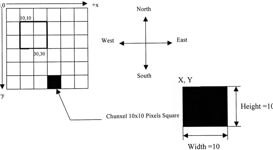
6.1.2. Javacoordinate system& directionalconventions
Java's coordinate system used pixels asits unit of measure. The origin coordinate 0,0 is in
the upper-left corner of the Applet window. The value of x coordinates increases to the
right of0,0 and y coordinates increases in adownward direction. This differs from other
drawing systems in which the 0,0 origin is atthe lower left and yvalues increases in an
upwarddirection. Allpixel values are integers;decimal numbers cannotbe usedto display
something between integer values. Hence the motion ofthe chunxel is proposed to be
incrementsordecrementsof one pixel unit.
The chunxels are shown onthe screen byusing fillRect() methodinJavathat draws solid
The x andycoordinates oftherectangle'stop left corner; thus the x andypositions
ofthechunxels andthe targetsarethetopleftcorner ofthesquares.
Thewidthoftherectangle (Chunxelwidth= 1 0
pixelunits)
Theheightoftherectangle (Chunxel height= 10
pixelunits)
The four directions that are used in the chunxel device are shown in the Figure 6 along
with the Java coordinate system. The North direction ofthe chunxel device is directed
upwards towards the origin, and the other directions are relative to this North direction. According to the above convention andthe Java coordinate system, amovementin North
is affected by subtracting one pixel unit from the y coordinate of the current chunxel
position, the South movement by adding one pixel unit to the y coordinate. Similarlythe Westmotionisbrought aboutby subtractingonepixel unit fromthe x coordinateandEast
motionbyaddingonepixelunitto thexcoordinate ofthechunxel position.
North
West East
South
X,Y
Height=10
Chunxel 10x10 Pixels Square
[image:34.526.58.493.344.583.2]Width=10
Figure 6: Javacoordinate system&Chunxel DimensionsinJava 2D
6.1.3. BasicControl Algorithm
Theessence ofthe chunxeldevice istoform a3D geometryby givinga setofcoordinates
23
ordertooccupy the specifictargets, the chunxelshaveto
move withinthe tank inspecific
directions. Thus simple controllogic forthismotionis asfollows:
1. Identifyingthetargettobe
occupied; 2. Movingtowardsthetarget; and 3.
Occupying
thetarget.Fornnumberoftargets with nnumber ofchunxels insidethetank,thechunxels will select
the target nearestto its current position. Since the chunxels are autonomous agents, allthe
chunxels inside the tank are given information about all the targetpositions. Basedonthe "Nearest Target"
rule the chunxel will
identify
the target, which itdesires to occupy. Thedistance betweenthecurrent chunxel positionandthe targetis givenby
Dist(CT)=
Sqrt((cnx+tnx)2+(cny+tny)2)
Where,
cnisthechunxel withidentificationnumbern,
tn isthe targetwithidentificationnumbern,and
x andyarethecoordinatesofthechunxel andtarget.
In the Java source code the square root is not considered, sincethe squared values ofthe
distances are directly compared with each other. This is done in order to reduce the
computational loadontheprogram. The distances betweeneach chunxel and allthe targets
are compared and the target, which is at the least distance from the chunxel under
consideration,is selectedbythatchunxel.
There can be a situation wheretwochunxels can select the same targetlocation; in such a
situation, the chunxel that reaches the target first, occupies the target. Once a target is
occupied, the occupied target andthe chunxel that occupies the target are "Locked". This
means that the chunxel that occupies the target and the occupied target are no longer
coordinates were supplied withinthe program. Ineither case it was necessaryto initialize
the target locations and initial chunxel positions. This was done by
creating two arrays
with two dimensions and n elements, one array for the chunxels and the other for the
targets; n is the number oftargets and chunxels to be initialized. It is assumed in this
program that the number of chunxels initialized is equal to the number targets to be
achieved.The first dimension isthereference numberoridentificationnumberofthe target
andthe chunxel. The seconddimension storesthexandycoordinates ofthe corresponding
chunxel ortarget. Thus thearraycanberepresentedina matrix shownin Table 1.
Table1: 2DArrayfor storing Chunxel Information in Java
1st
Dimension 2ndDimension
Identification# [0] [1] [2] [n]
[1] X y - ~
[2] X y - ~
[n] X y ~ ~
Addingtheabove control strategies to the simple control logic loop givesthebasiccontrol
algorithmthat the chunxelsandthechunxeldevice haveto follow.
BasiccontrolAlgorithm:
Step 1 Initializetargetpositions;
Step2
"Unlock"
alltargets, i.e. non-occupied;
Step3 Initializechunxelspositions;
Step4 "Free" all chunxels. i.e. chunxels are not occupying any targetposition andfree to
move;
Step5 Checkifany ofthe targetsare occupied;
Step6 Iftargetisoccupied;
"Lock"
thetargetandthechunxeloccupyingthattarget;
Step 7 Ifalltargetsare occupied gotostep 18;
Step8 Broadcast the
"Unlocked"
targets to the "Free
"
chunxels;
Step9 Selecttarget locations to be achievedby the chunxel based onthe "Nearest Target"
25
Step10 Decide the directionsfor the individual chunxels to move in towards the selected target;
Step 11 Storetheaboveinformationinthechunxelmemory; Step 12 Energizenorthcoil;
Step 13 Energizeeastcoil; Step 14 Energizesouthcoil; Step 15 Energizewestcoil; Step16 Gotostep6; and Step1 7 Endsimulation.
The direction to be pursued by the chunxel is decided by the relative position ofthe chunxel andthe target. Ifthechunxel isto the leftofthe target the chunxelhas to movein the East direction and if it is to the right ofthe target then it as to move in the west direction. Similarly,ifthe chunxelis belowthetarget,it hasto moveinnorthdirection and if it isabovethe target thenit hastomove south. Mathematically,
If,
ex- tx>0
=>chunxelis tothe right, Movewest cx-tx<0=>chunxelis tothe left, move east
cy-ty>0=>chunxelisbelow, move north
cy-ty <0=>chunxelisabove, move south
6.1.4. Collision Detection
In any simulation of a physical phenomenon or physical model it is necessaryto see that twoobjects do notoverlap orinterpenetrate. Collision detectionisa system of
determining
whether two or more objects collide. Collision detection is a computational geometryproblem. To make any simulation of a physical model realistic collision detection is essential.
Most collision detection methods usually deal with the temporary positions reflecting
1) Futurepositioncalculation;
2) Collisiondetection;and
3) Collisionhandling.
Thelogic governingobject motion wouldproceedina
loop
likethis:Entity oldPosition =
Entity currentPosition
Modify Entity
depending
uponthecontrollogicIfEntitycollidesthenEntity =
Entity oldPosition
Insimple wordsthelogic canbeexplained as follows:
Save thecurrent positioninatemporaryvariable;
Calculatethenewposition andsave itas currentposition; and
Ifat this current position the entity collides with any other entity then change the
current positionto thevalue storedinthetemporaryvariable.
Inthe above algorithm for collisiondetection, when objects collide, they are moved back
to thepreviousposition,becauseifthosewerethe safe spotsfortheobjects a moment ago,
they will probably be still safe. But there are complications inthemethod that we chose:
forexample, when an objectismovedbacktoits startingposition,care hastobetaken that
it is really still safe; if not (because an object might have moved in that space in the
meantime), then theoffendingobjectmustbe movedbacktoitsown startingposition. The
worstthatcanhappen is that all theobjects haveto bereverted backto theirown starting
points. This is an extremely slow way because it involves significant iteration (Blow
Jonathan, 1997)
The otherway to overcome the problem of collision detection inthe case ofchunxel 2D
simulation is collision avoidance. The principle is tomove only those chunxels,which do
nothave anypotentialcollision, takingplace withanyother chunxel. Itis alsovery easyto
predict the collision inthe case of chunxel simulationbecause all the chunxel are moving
inthe same directionor notmoving at all atanypoint oftime inthe simulation.This logic
. 27
factor to be considered in the 2D simulation program, the collision avoidance strategy is
bettersuitedforthisapplication.
Eithercollision detection orcollision avoidance, there has to be a
waytopredict whether
the objects interpenetrate or overlap each other. This is achieved
by using the "Bounding
box"
approach. Asimple waytocheck whetherthe
bounding
boxes intersect is"ifthe topsare higher than the bottoms and the lefts are 'letter' than the rights, then the boxes
intersect."
(MagarshakGreg, 2000). Figure7depictsthe
bounding
boxapproach.Figure 7:BoundingBox Collision Detection
A method for the chunxel collision detection was developed. This method checks for
future collisions that may take place and correspondingly modifies the position of the
chunxelunder consideration. Thecollisiondetectionor avoidancealgorithmisas follows:
Step 1 Takethechunxelidentificationnumberas an argumentforthedetectionmethod; Step2 Checkthedirection inwhichthechunxelismoving;
Step3 Ifchunxelmoving innorth or southdirectiongotostep5; Step4 Ifchunxelmoving ineast or westdirectiongotostep6;
Step5 Moving north or south: check ifany other chunxel position is between the colliding ranges.
Thiscanbeachievedby
a) Checkingifthex-coordinateof anyother chunxellies betweenthe (x-coordinateofthe
current chunxel- 9pixel
units)and(x-coordinate ofthecurrent chunxel+9pixelunits)
AND
b) Checkingifthey-coordinateof anyother chunxelisequalto10pixel unitsfromthe
Step6 Moving east or west: check ifany other chunxel position is between the
colliding
ranges.
Thiscanbeachievedby
a) Checking ifthey-coordinateof anyother chunxelliesbetweenthe(y-coordinateofthe
currentchunxel- 9
pixelunits)and(y-coordinateofthecurrent chunxel+9pixelunits)
AND
b) Checking ifthex-coordinateof anyotherchunxelis equalto10pixel unitsfromthe
x-coordinateofthecurrentchunxel
Step 7 Ifcollision isnotdetectedadvance theposition ofthechunxelbyone unitinthe
pre-determineddirectionelsedonot changethepositionofthechunxel.
6.1.5. ProportionalMotion
The first prototype run showed that the chunxels continuously oscillate about the target
position. This is because of the gravity and buoyancy effects, collisions and also the
constant cycle time that even after being locked to a specifictarget the chunxels keep on
hunting for the targetposition. To minimize this "Hunting ofthe Target" a "Proportional
Motion"
method is implemented. Although in the 2D simulation program, the hunting
effect cannotbe observed sinceonly integervalues are acceptedforthecoordinate byJava
even then the proportional motion logic was employed so that it could help in extending
thesamelogicto the3D simulation program.
The logic behind proportional motion is to take bigger steps when the target is far way
from the current chunxel position and as the chunxel approaches the target go on taking
smaller and smaller steps. In an actual device this can be achieved by turning ON the
internal coil for a certain percentage ofthe cycle time. Thus by controlling the Time ON
forthe internal coil insidethe chunxel, the timeforwhichthemagneticforce ofpropulsion
thatacts onthe chunxel canbecontrolled. Inthis waythe displacement ofthe chunxel can
be made smaller as itapproaches the target. Ifthe distance betweenthe chunxel andtarget
is greater than the size ofthe chunxel then the chunxel takes multiple steps towards the
target, else it takes only one step. This distance was termed as the "threshold distance."
29
eachtime the distance between the target and current chunxelposition is checked, and if
the distance is greater than tenpixel units, then the position ofthe chunxel is updated by
one pixel unit towards the target. Figure 8 makes it easierto understand the principle of
proportional motion method. Sincethe 2D simulationtool doesnottake into consideration
the cycletime, and actual propulsionforce arbitraryvalues were selected forthe threshold
distance, andthe number of maximum stepsthat the chunxel takes ifthe distance between
the chunxelandthetargetis less than the thresholddistance.
&
Multiplestepstobe [Jtaken
Chunxel
>Thresholddistance(td)
< ?
<td
P
1 steptobetaken
1 steptobetaken
| | Target
?
r
+\
Figure 8:Proportional FeedbackMotion in 2D Simulation Tool
The logic that was used to implement proportional motion can be expressed in the
followingalgorithm:
Step 1 For any directionalcoilthatisenergized:create aloopcount= 0
Step2 Ifcount= 0goto step 4
Step3 Ifcount> 0gotostep 5
Step4 Advancethe chunxel positionbyone pixel unitinthedetermined direction. Changethe
positionofthechunxelonlyifthere isnocollisiondetectedforthefutureposition.
Step5 Ifthe difference between the targetposition and current chunxel position is
greater
than 10pixels unit after pixel units then onlyadvance theposition ofthe chunxel by
one unitinthe determined direction. Changethe
positionofthechunxelonlyifthere is
nocollisiondetectedforthefutureposition.
Step7 End: energizing ofthecoil.Moveto thenext coilenergizingsequence.
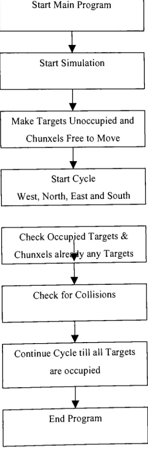
Combining the basic control algorithm with the collision detection and proportional
feedback motionalgorithms gives thebasic framework ofthe 2D simulation program. The
basic flow ofthe Java program is as shownin Figure 9. The detailed flow ofinstructions
and conditionallooping oftheprograminshown inAppendix A intheform ofaflowchart.
Start Main Program
Start Simulation
Make Targets Unoccupiedand
ChunxelsFreetoMove
Start Cycle
West, North,EastandSouth
Check OccupiedTargets &
Chunxels alre^yany Targets
I
Check forCollisions
ContinueCycletillallTargets
areoccupied
I
End Program
[image:42.525.197.342.204.643.2]31
6.2. Phase 2:
Demonstration
ofSynergistic
behavior using 2-D Simulation Tool
One of the most innovative parts ofthis research
was, not only the generation of static
structures,butalsothedynamic behaviorofthose structures. Theproposedapproach atthe
beginning ofthe research was to form a static structure and the ability to demonstrate a
dynamic behavior forthe structure. The basic approach to navigation and control was to
implement a swarm style behavior that would allow all chunxels to stand on a common
non-hierarchical platform with one another, behave autonomouslyyet withcollective goals
and synergistic functionality. This phase ofresearch was dedicated solely to demonstrate
that the chunxels could exhibit collective synergistic behaviorand completetasks together
thatcould notbecompleted asindividuals.
One such task is "building of a chunxel platform with an individual chunxel atop the
platform. Once the structure is built the next step is to raise the individual chunxel up
above the level oftank medium."
This behavior would be impossible for an individual
chunxel, butcan beaccomplishedbythe group workingtogether.
An algorithm was developed in this phase to accomplish this task. During this phase, a
strategy was also developed to overcome deadlock situations for the chunxels while
moving towards theirrespectivetargets. The deadlock situationis defined when achunxel
cannotreach its target location due to thepresence of some obstruction, generally another
chunxel that is stationary on its achieved target. A search sub-routine was developed to
findan alternative pathtowards thetargetto bereached.
6.2.1. Synergistic behavioralgorithm
The above-mentioned task of lifting an individual chunxel above the liquid level was
demonstrated by developing the synergistic behavior algorithm. In order to lift a chunxel
abovetheliquidmediuminsidethe tank thefollowing steps werefollowed:
Determinationofthetargetsinordertofromaplatformbeneaththatchunxel.
Broadcastingofthetargetstotheavailable chunxelsinsidethe tank.
Once theplatform has beencreated,
broadcasting
adesired deltamovement foreachchunxel.
Figure 10 belowshows thesimulation andtheformationoftheplatform andthemovement
ofthechunxelsinordertoliftachunxel above theliquidmedium.
slowerj faster
*
i yjU\
| slowBi| faster j
Figure 10: 2D Simulation Tool Screenshots
The incremental deltamovement is givenby looping theprogram insuch a waythat once
one deltamovement is achieved thenext set ofdeltatargets is givento the chunxels. This
isrepeated untilthelastset oftargets orthe co-ordinatesofthe targetswheretheindividual
chunxelisabovetheliquid levelis achieved.
The formation of a platform is fairly easy when the chunxel to be lifted is away from the
walls ofthe tanks. But inthe scenario where the chunxelto be lifted is close to the walls
the platform cannot be made. In such special case scenarios the chunxel to be lifted is
pulled away from the other chunxels andthenwhen it is sufficiently away from thewalls
and enough room is available to form the platform beneath the original algorithm is run
33
Thus an addition to the original algorithm is made. Before
broadcasting
the targets, thesystem sees the position ofthe chunxel which is to be lifted and ifit is