UNIVERSITY OF SOUTHERN QUEENSLAND
MEASURING, MODELLING AND UNDERSTANDING
THE MECHANICAL BEHAVIOUR OF BAGASSE
A Dissertation submitted by
Floren Plaza BE (Civil Hons)
For the award of
Doctor of Philosophy
September, 2002
i
ABSTRACT
In the Australian sugar industry, sugar cane is smashed into a straw like material by
hammers before being squeezed between large rollers to extract the sugar juice.
The straw like material is initially called prepared cane and then bagasse as it passes
through successive roller milling units. The sugar cane materials are highly
compressible, have high moisture content, are fibrous, and they resemble some peat
soils in both appearance and mechanical behaviour.
A promising avenue to improve the performance of milling units for increased
throughput and juice extraction, and to reduce costs is by modelling of the crushing
process. To achieve this, it is believed necessary that milling models should be able
to reproduce measured bagasse behaviour.
This investigation sought to measure the mechanical (compression, shear, and
volume) behaviour of prepared cane and bagasse, to identify limitations in currently
used material models, and to progress towards a material model that can predict
bagasse behaviour adequately.
Tests were carried out using a modified direct shear test equipment and procedure at
most of the large range of pressures occurring in the crushing process. The
investigation included an assessment of the performance of the direct shear test for
measuring bagasse behaviour. The assessment was carried out using finite element
modelling.
iii
ACKNOWLEDGMENTS
I wish to thank my supervisors, Assoc. Prof. Harry Harris from the University of
Southern Queensland, and Dr. Mac Kirby from the CSIRO Land and Water, for
their guidance and patience throughout the project, and for their friendship. Their
advice has been invaluable to me.
I would like to thank John Williams for his major contribution in the design and
preparation of the equipment, and in carrying out the tests safely and efficiently.
Neil McKenzie ensured that the press equipment was fixed in time to carry out the
experimental tests. Neil McKenzie and Allan Connor both supervised and carried
out the required electronic and hydraulic work. Peter Everitt provided measurement
and control advice.
The assistance of Gordon Ingram, Steven Pennisi, Anthony Mann, Gaye Davy, and
Ramesh Ponnuswami in carrying out the 1998 tests, and Letitia Langens in carrying
out the 2001 tests, is acknowledged. Letitia Langens was also the co-author of
several conference papers. The staff of Pleystowe Mill and Racecourse Mill
provided assistance in obtaining the cane and also cane analysis information.
Matt Schembri provided support and advice particularly in the early stages of this
work.
Geoff Kent provided advice, and also assistance in running several computer
packages.
The following people were of great help to me during this investigation and I thank
them: Anthony Mann for mathematical advice. Ann Ellis in finding and obtaining
publications. Stewart McKinnon, Col Benson, and Geoff Kent provided assistance
with numerous computer applications and problems.
Christine Bartlett at the Research and Higher Degrees Office at USQ provided help
in progress and administrative matters.
iv
CSR Limited gave permission to publish operating mill data from one of its
factories.
I would like to thank: Terry Dixon for championing the funding of this
investigation, and for his encouragement. The Sugar Research Institute Board for
its vision in the initial funding. The Faculty of Engineering and Surveying at the
University of Southern Queensland for its scholarship, which allowed the
investigation to be progressed. The Australian sugar mills for providing additional
funds through Sugar Research Institute levy funding; and the Sugar Research and
Development Corporation for part funding of the 2001 experimental tests.
This thesis is dedicated to Allan Connor, who passed away suddenly in September
2002.
v
Measuring, modelling and understanding the
mechanical behaviour of bagasse
Contents
1
Chapter 1 – The need for a better understanding of bagasse
behaviour ...1
1.1 Introduction – the hypothesis... 1
1.2 Background... 1
1.3 Previous work on the milling process ... 4
1.4 Explanation of the critical state concept... 6
1.5 Experimental investigation of critical state models ... 10
1.6 Derivation of critical state parameters ... 11
1.7 Inverse methods for obtaining material parameters ... 12
1.8 The current state of material models for prepared cane ... 16
1.9 Review of available test methods to measure critical state behaviour.. 16
1.10 Summary of objectives ... 19
2
Chapter 2 – A search for similar materials, related tests, and
promising models...20
2.1 Introduction... 20
2.2 Similar materials to prepared cane and bagasse ... 20
2.2.1 Peat – an organic soil ... 20
2.2.2 Other similar materials to bagasse ... 25
2.3 The soil direct shear test ... 26
2.4 Material
models ... 30
2.5 Summary of Chapter 2 ... 33
3
Chapter 3 – Preliminary direct shear tests to measure bagasse
behaviour ...34
3.1 Introduction... 34
3.2 Over-consolidated test on prepared cane using sandpaper as the rough
surface. ... 38
3.3 Tests showing effect of different surface plate geometries and test
procedures on water pressure... 41
3.4 Towards finalising the test geometry and procedure ... 45
vi
3.4.2 Further tests to improve vertical pressure control ... 55
3.5 Summary of Chapter 3 ... 56
4
Chapter 4 – Experimental results at pressures in the pressure
feeder...57
4.1 Introduction... 57
4.2 Test geometry and equipment... 57
4.3 Test
procedure... 61
4.4 Main test series ... 63
4.5 Summary of Chapter 4 ... 97
5
Chapter 5 – Modelling the compression, shear and volume
behaviour of bagasse ...99
5.1 Introduction... 99
5.2 Fitting predictions to experimental results using a single element
Modified Cam Clay model ... 99
5.2.1 Compression along the normal compression line ... 105
5.2.2 Compression unloading of a bagasse sample ... 107
5.2.3 Compression when reloading a final bagasse sample ... 110
5.2.4 Shearing of a normally consolidated bagasse sample. ... 110
5.2.5 Shearing of an over-consolidated final bagasse sample... 112
5.2.6 Summary of fitting predictions to experimental results using a
single element Modified Cam Clay model... 114
5.3 Fitting predictions to experimental results using a multi-element
Modified Cam Clay model. ... 114
5.3.1 Predictions for loading conditions 1 to 4... 115
5.3.2 Predictions for loading condition 5... 116
5.3.3 Summary of multi-element simulations ... 122
5.4 Indirect material parameter estimation by model inversion ... 122
5.4.1 Indirect parameter estimation from normal compression loading
step data... 124
5.4.2 Indirect parameter estimation from elastic re-loading step data 127
5.4.3 Indirect parameter estimation from shearing step data ... 131
5.4.4
Summary of material parameters from indirect parameter
estimation ... 133
5.5 Performance of critical state models in use at this time ... 135
5.6 Summary of Chapter 5 ... 141
6
Chapter 6 - Comparison of modified direct shear test geometry
with classical split box geometry...143
vii
6.2 Direct shear test simulations for normally consolidated final bagasse
with a sideways displacement of 13 mm... 146
6.3 Direct shear test simulations for normally consolidated final bagasse
with a sideways displacement of 19.5 mm ... 162
6.4 Direct shear test simulations for over-consolidated final bagasse with a
sideways displacement of 16.0 mm ... 168
6.4.1 Coefficient of friction of 0.6... 168
6.4.2 Coefficient of friction to achieve good grip and formation of shear
planes in over-consolidated bagasse sample ... 173
6.5 Summary of Chapter 6 ... 185
7
Chapter 7 – Direct shear test measurements of bagasse
behaviour at pressures occurring in the three main rolls ...187
7.1 Introduction... 187
7.2 Test geometry and equipment... 187
7.3 Test
procedure... 190
7.4 Test series at pressures in the main three rolls ... 190
7.5 General behaviour of bagasse at pressures in the main three rolls ... 191
7.6 Detail of material behaviour and magnitudes of material parameters 199
7.6.1 Slopes of the normal compression line and elastic
unloading-reloading line ... 199
7.6.2 Volumetric strain during shearing and position of critical state line
with respect to normal compression line ... 200
7.6.3 Equivalent friction angle of the critical state line ... 203
7.6.4 An estimate of the dilatancy angle for bagasse. ... 206
7.7 The effect of pressure and over-consolidation on the grip of the roll
surface on bagasse – friction and shear coefficients ... 209
7.7.1 Shear stresses ... 210
7.7.2 Coefficients of internal shear... 213
7.8 Differentiation of cane varieties... 217
7.9 Summary of Chapter 7 ... 220
8
Chapter 8 – Development of improved material model for
bagasse ...222
8.1 Introduction... 222
8.2 Desirable features of a material model for bagasse ... 222
8.2.1 M and K
ovalues... 222
8.2.2 Shapes of the yield and potential surfaces... 223
8.2.3 Non-associated flow... 224
viii
8.3 Improved predictions using an associated Modified Cam Clay model
with a
β
extension ... 225
8.4 Predictions from a material model in the soil mechanics literature. ... 232
8.5 Summary of Chapter 8 ... 245
9
Chapter 9 – Application to mill modelling ...247
9.1 Introduction... 247
9.2 Description of the Victoria mill B1 pressure feeder ... 247
9.3 Prediction of mill operating parameters using milling theory and direct
shear test results ... 250
9.4 Prediction of mill operating parameters using multi-element modelling
and direct shear test results ... 257
9.4.1 Implementation of modified 1 of Yu’s (1998) model into
ABAQUS subroutine ... 258
9.4.2 Simulations of a three roll pressure feeder using a Modified Cam
Clay model with
β
=0.21 and a corresponding Drucker-Prager Cap
model... 259
9.4.3 Simulations of the first two rolls of the Victoria B1 pressure
feeder using a Drucker-Prager Cap model with R=0.23 ... 280
9.4.4 Simulations of the first two rolls (horizontally aligned) of the
Victoria B1 pressure feeder using a Drucker-Prager Cap model
with R=0.23 ... 284
9.5 Summary of Chapter 9 ... 289
10
Chapter 10 – Summary, conclusions and recommendations 291
10.1 Summary and conclusions ... 291
10.2 Recommendations ... 299
10.2.1 Experimental
tests... 299
10.2.2 Improved material model for bagasse... 301
10.2.3 Improved modelling of the pressure feeder ... 302
11
Published technical papers...303
ix
[image:10.595.129.522.68.777.2]List of Tables
Table 2.1 Typical make up of prepared cane ...20
Table 2.2 A comparison of typical parameter values for peat and prepared cane. ...22
Table 4.1 Description of direct shear tests at pressure feeder compactions...65
Table 4.2 Normal compression line values for final bagasse, 4-12-98 tests ...75
Table 4.3 Normal compression line values for first bagasse, 3-12-98 tests ...79
Table 4.4 Normal compression line values for first bagasse, 5-12-98 tests ...83
Table 4.5 Normal compression line values for prepared cane, 7-12-98 tests...87
Table 4.6 Normal compression line values for prepared cane, 8-12-98 tests...91
Table 4.7 Summary of determined material parameters...95
Table 5.1 Summary of material parameters for single element MCC predictions...104
Table 5.2 Summary of material parameters for best fit of normal compression line...124
Table 5.3 Correlation coefficient matrix for normal compression line... 124
Table 5.4 Summary of material parameters for best fit of elastic re-loading compression line ... 127
Table 5.5 Correlation coefficient matrix for compression along the elastic line...128
Table 5.6 Revised summary of material parameters for best fit of elastic re-loading compression line...129
Table 5.7 Summary of material parameters for best fit of the shearing behaviour of a normally consolidated final bagasse sample... 131
Table 5.8 Correlation coefficient matrix for shearing. ... 131
Table 5.9 Optimal parameter values and limits... 133
Table 6.1. Material parameters and initial stress conditions for normally consolidated final bagasse sample ... 146
Table 6.2 Predictions of single element quasi-analytical model for a sideways displacement of 13 mm ...160
Table 6.3 Predictions of coarse mesh split box model for a sideways displacement of 13 mm... 160
Table 6.4 Predictions of fine mesh split box model for a sideways displacement of 13 mm ...160
x
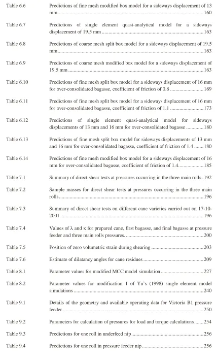
Table 6.6 Predictions of fine mesh modified box model for a sideways displacement of 13
mm... 160
Table 6.7 Predictions of single element quasi-analytical model for a sideways displacement of 19.5 mm ...163
Table 6.8 Predictions of coarse mesh split box model for a sideways displacement of 19.5 mm... 163
Table 6.9 Predictions of coarse mesh modified box model for a sideways displacement of 19.5 mm ...163
Table 6.10 Predictions of fine mesh split box model for a sideways displacement of 16 mm for over-consolidated bagasse, coefficient of friction of 0.6 ...169
Table 6.11 Predictions of fine mesh split box model for a sideways displacement of 16 mm for over-consolidated bagasse, coefficient of friction of 1.1 ...173
Table 6.12 Predictions of single element quasi-analytical model for sideways displacements of 13 mm and 16 mm for over-consolidated bagasse ...180
Table 6.13 Predictions of fine mesh split box model for sideways displacements of 13 mm and 16 mm for over-consolidated bagasse, coefficient of friction of 1.4 ...180
Table 6.14 Predictions of fine mesh modified box model for a sideways displacement of 16 mm for over-consolidated bagasse, coefficient of friction of 1.4... 185
Table 7.1 Summary of direct shear tests at pressures occurring in the three main rolls .192 Table 7.2 Sample masses for direct shear tests at pressures occurring in the three main rolls...196
Table 7.3 Summary of direct shear tests on different cane varieties carried out on 17-10-2001 ...196
Table 7.4 Values of λ and κ for prepared cane, first bagasse, and final bagasse at pressure feeder and three main rolls pressures. ...200
Table 7.5 Position of zero volumetric strain during shearing ...203
Table 7.6 Estimate of dilatancy angles for cane residues ... 209
Table 8.1 Parameter values for modified MCC model simulation ... 227
Table 8.2 Parameter values for modification 1 of Yu’s (1998) single element model simulations ...240
Table 9.1 Details of the geometry and available operating data for Victoria B1 pressure feeder ...250
Table 9.2 Parameters for calculation of pressures for load and torque calculations...254
Table 9.3 Predictions for one roll in underfeed nip... 256
xi
Table 9.5 Predicted torques for Victoria Mill no.1 pressure feeder configuration ...257
Table 9.6 Nip clearances for modelled roll diameters ... 262
Table 9.7 Predicted roll loads and torques from three roll simulations ... 278
Table 9.8 Predicted roll loads and torques from two roll simulations ... 280
xii
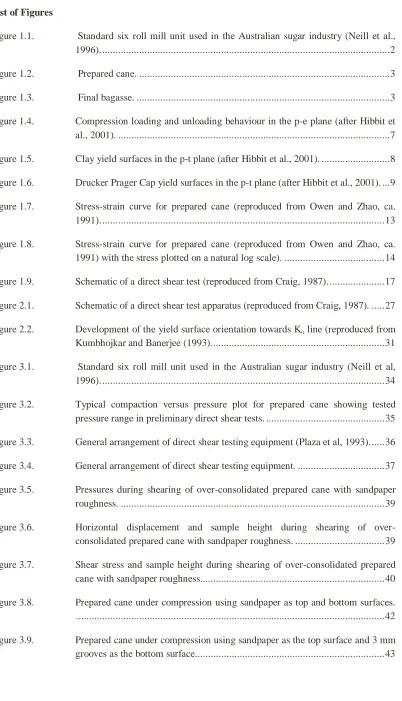
[image:13.595.123.525.70.771.2]List of Figures
Figure 1.1. Standard six roll mill unit used in the Australian sugar industry (Neill et al., 1996)...2
Figure 1.2. Prepared cane. ...3
Figure 1.3. Final bagasse. ...3
Figure 1.4. Compression loading and unloading behaviour in the p-e plane (after Hibbit et al., 2001). ...7
Figure 1.5. Clay yield surfaces in the p-t plane (after Hibbit et al., 2001). ...8
Figure 1.6. Drucker Prager Cap yield surfaces in the p-t plane (after Hibbit et al., 2001). ...9
Figure 1.7. Stress-strain curve for prepared cane (reproduced from Owen and Zhao, ca. 1991)...13
Figure 1.8. Stress-strain curve for prepared cane (reproduced from Owen and Zhao, ca. 1991) with the stress plotted on a natural log scale). ...14
Figure 1.9. Schematic of a direct shear test (reproduced from Craig, 1987)...17
Figure 2.1. Schematic of a direct shear test apparatus (reproduced from Craig, 1987). ...27
Figure 2.2. Development of the yield surface orientation towards Ko line (reproduced from
Kumbhojkar and Banerjee (1993)...31
Figure 3.1. Standard six roll mill unit used in the Australian sugar industry (Neill et al, 1996)...34
Figure 3.2. Typical compaction versus pressure plot for prepared cane showing tested pressure range in preliminary direct shear tests. ...35
Figure 3.3. General arrangement of direct shear testing equipment (Plaza et al, 1993)...36
Figure 3.4. General arrangement of direct shear testing equipment. ...37
Figure 3.5. Pressures during shearing of over-consolidated prepared cane with sandpaper roughness. ...39
Figure 3.6. Horizontal displacement and sample height during shearing of over-consolidated prepared cane with sandpaper roughness. ...39
Figure 3.7. Shear stress and sample height during shearing of over-consolidated prepared cane with sandpaper roughness...40
Figure 3.8. Prepared cane under compression using sandpaper as top and bottom surfaces. ...42
xiii
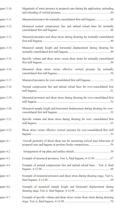
Figure 3.10. Magnitude of water pressure in prepared cane during the application, unloading and reloading of vertical pressure. ...44
Figure 3.11. Measured pressures for normally consolidated first mill bagasse. ...48
Figure 3.12. Measured normal compression line and unload reload lines for normally consolidated first mill bagasse...48
Figure 3.13. Measured pressures and shear stress during shearing for normally consolidated first mill bagasse...49
Figure 3.14. Measured sample height and horizontal displacement during shearing for normally consolidated first mill bagasse. ...49
Figure 3.15. Specific volume and shear stress versus shear strain for normally consolidated first mill bagasse...50
Figure 3.16. Measured shear stress versus effective vertical pressure for normally consolidated first mill bagasse...50
Figure 3.17. Measured pressures for over-consolidated first mill bagasse...51
Figure 3.18. Normal compression line and unload reload lines for over-consolidated first mill bagasse. ...51
Figure 3.19. Measured pressures and shear stress during shearing for over-consolidated first mill bagasse. ...52
Figure 3.20. Measured sample height and horizontal displacement during shearing for over-consolidated first mill bagasse...52
Figure 3.21. Specific volume and shear stress during shearing for over- consolidated first mill bagasse. ...53
Figure 3.22. Shear stress versus effective vertical pressure for over-consolidated first mill bagasse. ...53
Figure 4.1. Overall geometry of direct shear test for measuring critical state behaviour of prepared cane and bagasse at pressure feeder compactions...58
Figure 4.2. Arrangement of top plate and surface details...59
Figure 4.3. Example of measured pressures, Test A, final bagasse, 4-12-98. ...67
Figure 4.4. Example of normal compression line and unload reload lines, Test A, final bagasse, 4-12-98. ...68
Figure 4.5. Example of measured pressures and shear stress during shearing stage, Test A, final bagasse, 4-12-98. ...69
Figure 4.6. Example of measured sample height and horizontal displacement during shearing stage, Test A, final bagasse, 4-12-98...69
xiv
Figure 4.8. Example of shear stress versus effective vertical pressure during shearing stage, Test A, final bagasse, 4-12-98. ...71
Figure 4.9. Normal compression line and elastic unloading reloading line for final bagasse, 4-12-98 tests. ...75
Figure 4.10. Normalized shear stress versus shear strain plot for final bagasse, 4-12-98 tests. ...76
Figure 4.11. Volumetric strain versus shear strain plot for final bagasse, 4-12-98 tests...76
Figure 4.12. Plot of shear stress / effective vertical pressure versus volumetric strain to estimate M for final bagasse, 4-12-98 tests. ...77
Figure 4.13. Plot of volumetric strain versus normalised effective vertical pressure to estimate the no volume change over-consolidation ratio for final bagasse, 4-12-98 tests. ...77
Figure 4.14. Plot of normalised shear stress versus normalised effective vertical pressure to estimate the equivalent critical state friction line and M for final bagasse, 4-12-98 tests. ...78
Figure 4.15. Plot of specific volume versus effective vertical pressure to estimate the critical state line for final bagasse, 4-12-98 tests...78
Figure 4.16. Normal compression line and elastic unloading-reloading line for first bagasse, 3-12-98 tests. ...79
Figure 4.17. Normalised shear stress versus shear strain plot for first bagasse, 3-12-98 tests. ...80
Figure 4.18. Volumetric strain versus shear strain plot for first bagasse, 3-12-98 tests...80
Figure 4.19. Plot of shear stress / effective vertical pressure versus volumetric strain to estimate M for first bagasse, 3-12-98 tests. ...81
Figure 4.20. Plot of volumetric strain versus normalised effective vertical pressure to estimate the no volume change over-consolidation ratio for first bagasse, 3-12-98 tests. ...81
Figure 4.21. Plot of normalised shear stress versus normalised effective vertical pressure to estimate the equivalent critical state friction line and M for first bagasse, 3-12-98 tests. ...82
Figure 4.22. Plot of specific volume versus effective vertical pressure to estimate the critical state line for first bagasse, 3-12-98 tests...82
Figure 4.23. Normal compression line and elastic unloading-reloading line for first bagasse, 5-12-98 tests. ...83
Figure 4.24. Normalised shear stress versus shear strain plot for first bagasse, 5-12-98 tests. ...84
xv
Figure 4.26. Plot of shear stress / effective vertical pressure versus volumetric strain to estimate M for first bagasse, 5-12-98 tests. ...85
Figure 4.27. Plot of volumetric strain versus normalised effective vertical pressure to estimate the no volume change over-consolidation ratio for first bagasse, 5-12-98 tests. ...85
Figure 4.28. Plot of normalised shear stress versus normalised effective vertical pressure to estimate the equivalent critical state friction line and M for first bagasse, 5-12-98 tests. ...86
Figure 4.29. Plot of specific volume versus effective vertical pressure to estimate the critical state line for first bagasse, 5-12-98 tests...86
Figure 4.30. Normal compression line and elastic unloading-reloading line for prepared cane, 7-12-98 tests. ...87
Figure 4.31. Normalised shear stress versus shear strain plot for prepared cane, 7-12-98 tests. ...88
Figure 4.32. Volumetric strain versus shear strain plot for prepared cane, 7-12-98 tests. ....88
Figure 4.33. Plot of shear stress / effective vertical pressure versus volumetric strain to estimate M for prepared cane, 7-12-98 tests...89
Figure 4.34. Plot of volumetric strain versus normalised effective vertical pressure to estimate the no volume change over-consolidation ratio for prepared cane, 7-12-98 tests. ...89
Figure 4.35. Plot of normalised shear stress versus normalised effective vertical pressure to estimate the equivalent critical state friction line and M for prepared cane, 7-12-98 tests. ...90
Figure 4.36. Plot of specific volume versus effective vertical pressure to estimate the critical state line for prepared cane, 7-12-98 tests. ...90
Figure 4.37. Normal compression line and elastic unloading-reloading line for prepared cane, 8-12-98 tests. ...91
Figure 4.38. Normalised shear stress versus shear strain plot for prepared cane, 8-12-98 tests. ...92
Figure 4.39. Volumetric strain versus shear strain plot for prepared cane, 8-12-98 tests. ....92
Figure 4.40. Plot of shear stress / effective vertical pressure versus volumetric strain to estimate M for prepared cane, 8-12-98 tests...93
Figure 4.41. Plot of volumetric strain versus normalised effective vertical pressure to estimate the no volume change over-consolidation ratio for prepared cane, 8-12-98 tests. ...93
xvi
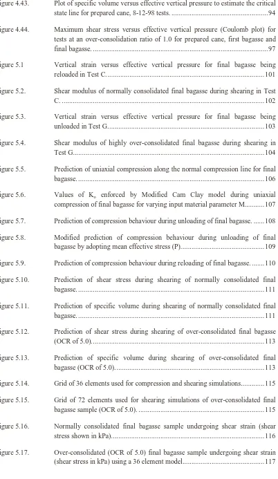
Figure 4.43. Plot of specific volume versus effective vertical pressure to estimate the critical state line for prepared cane, 8-12-98 tests. ...94
Figure 4.44. Maximum shear stress versus effective vertical pressure (Coulomb plot) for tests at an over-consolidation ratio of 1.0 for prepared cane, first bagasse and final bagasse. ...97
Figure 5.1 Vertical strain versus effective vertical pressure for final bagasse being reloaded in Test C...101
Figure 5.2. Shear modulus of normally consolidated final bagasse during shearing in Test C. ...102
Figure 5.3. Vertical strain versus effective vertical pressure for final bagasse being unloaded in Test G...103
Figure 5.4. Shear modulus of highly over-consolidated final bagasse during shearing in Test G... 104
Figure 5.5. Prediction of uniaxial compression along the normal compression line for final bagasse. ...106
Figure 5.6. Values of Ko enforced by Modified Cam Clay model during uniaxial
compression of final bagasse for varying input material parameter M...107
Figure 5.7. Prediction of compression behaviour during unloading of final bagasse. ...108
Figure 5.8. Modified prediction of compression behaviour during unloading of final bagasse by adopting mean effective stress (P)...109
Figure 5.9. Prediction of compression behaviour during reloading of final bagasse. ...110
Figure 5.10. Prediction of shear stress during shearing of normally consolidated final bagasse. ...111
Figure 5.11. Prediction of specific volume during shearing of normally consolidated final bagasse. ...111
Figure 5.12. Prediction of shear stress during shearing of over-consolidated final bagasse (OCR of 5.0)...113
Figure 5.13. Prediction of specific volume during shearing of over-consolidated final bagasse (OCR of 5.0). ...113
Figure 5.14. Grid of 36 elements used for compression and shearing simulations...115
Figure 5.15. Grid of 72 elements used for shearing simulations of over-consolidated final bagasse sample (OCR of 5.0). ...115
Figure 5.16. Normally consolidated final bagasse sample undergoing shear strain (shear stress shown in kPa)...116
xvii
Figure 5.18. Over-consolidated (OCR of 5.0) final bagasse sample undergoing shear strain (shear stress in kPa) using a 72 element model... 117
Figure 5.19. Multi-element prediction of shear stress versus shear strain during shearing of over-consolidated final bagasse (OCR of 5.0). ...119
Figure 5.20. Multi-element prediction of specific volume versus shear strain during shearing of over-consolidated final bagasse (OCR of 5.0)...119
Figure 5.21. Over-consolidated (OCR of 5.0) final bagasse sample undergoing shear strain (shear stress shown in kPa) using a 72 element model and adopting a variation in input material parameters (Ko =0.69, ν=0.01). ...120
Figure 5.22. Multi-element prediction of shear stress during shearing of over-consolidated final bagasse (OCR of 5.0) and adopting a variation in input material parameters (Ko =0.69, ν=0.01). ...121
Figure 5.23. Multi-element prediction of specific volume during shearing of over-consolidated final bagasse (OCR of 5.0) and adopting a variation in input material parameters (Ko =0.69, ν=0.01). ...121
Figure 5.24. Fit of normal compression line using PEST best fit parameters. ...124
Figure 5.25 Sum of squared deviations for compression along normal compression line. 126
Figure 5.26. Fit of elastic re-loading compression line using PEST best fit parameters...127
Figure 5.27. Sum of squared deviations (SSD) no more than 10% higher than the minimum SSD found by PEST (with varying Ko and κ). ...129
Figure 5.28 Sum of squared deviations for compression along the elastic line... 130
Figure 5.29. Fit of shear stress versus shear strain for normally consolidated final bagasse using PEST best fit parameters... 132
Figure 5.30. Fit of specific volume versus shear strain for normally consolidated final bagasse using PEST best fit parameters. ... 132
Figure 5.31 Sum of squared deviations for shearing of a normally consolidated sample. .134
Figure 5.32. Reproducing compression behaviour of final mill bagasse using the DPC model. ... 137
Figure 5.33. Reproducing compression unloading behaviour of final mill bagasse using the MCC and DPC models... 138
Figure 5.34. Reproducing compression re-loading behaviour of final mill bagasse using the DPC model. ... 139
Figure 5.35. Reproducing shear stress versus shear strain behaviour of normally consolidated final mill bagasse using the DPC model... 140
xviii
Figure 6.1. Vertical stress (kPa) for normally consolidated final bagasse, split box geometry, displacement 13 mm, coarse mesh...147
Figure 6.2. Horizontal stress (kPa) for normally consolidated final bagasse, split box geometry, displacement 13 mm, coarse mesh...147
Figure 6.3. Shear stress (kPa) for normally consolidated final bagasse, split box geometry, displacement 13 mm, coarse mesh...148
Figure 6.4. Shear strain for normally consolidated final bagasse, split box geometry, displacement 13 mm, coarse mesh...148
Figure 6.5. Confining pressure (kPa) for normally consolidated final bagasse, split box geometry, displacement 13 mm, coarse mesh...149
Figure 6.6. Void ratio for normally consolidated final bagasse, split box geometry, displacement 13 mm, coarse mesh...149
Figure 6.7. Vertical stress (kPa) for normally consolidated final bagasse, modified box geometry, displacement 13 mm, coarse mesh...150
Figure 6.8. Horizontal stress (kPa) for normally consolidated final bagasse, modified box geometry, displacement 13 mm, coarse mesh...150
Figure 6.9. Shear stress (kPa) for normally consolidated final bagasse, modified box geometry, displacement 13 mm, coarse mesh...151
Figure 6.10. Shear strain for normally consolidated final bagasse, modified box geometry, displacement 13 mm, coarse mesh...151
Figure 6.11. Confining pressure (kPa) for normally consolidated final bagasse, modified box geometry, displacement 13 mm, coarse mesh...152
Figure 6.12. Void ratio for normally consolidated final bagasse, modified box geometry, displacement 13 mm, coarse mesh...152
Figure 6.13. Vertical stress (kPa) for normally consolidated final bagasse, split box geometry, displacement 13 mm, fine mesh. ...153
Figure 6.14. Horizontal stress (kPa) for normally consolidated final bagasse, split box geometry, displacement 13 mm, fine mesh. ...153
Figure 6.15. Shear stress (kPa) for normally consolidated final bagasse, split box geometry, displacement 13 mm, fine mesh...154
Figure 6.16. Shear strain for normally consolidated final bagasse, split box geometry, displacement 13 mm, fine mesh...154
Figure 6.17. Confining pressure (kPa) for normally consolidated final bagasse, split box geometry, displacement 13 mm, fine mesh. ...155
xix
Figure 6.19. Vertical stress (kPa) for normally consolidated final bagasse, modified box geometry, displacement 13 mm, fine mesh. ...156
Figure 6.20. Horizontal stress (kPa) for normally consolidated final bagasse, modified box geometry, displacement 13 mm, fine mesh. ...156
Figure 6.21. Shear stress (kPa) for normally consolidated final bagasse, modified box geometry, displacement 13 mm, fine mesh. ...157
Figure 6.22. Shear strain for normally consolidated final bagasse, modified box geometry, displacement 13 mm, fine mesh...157
Figure 6.23. Confining pressure (kPa) for normally consolidated final bagasse, modified box geometry, displacement 13 mm, fine mesh. ...158
Figure 6.24. Void ratio for normally consolidated final bagasse, modified box geometry, displacement 13 mm, fine mesh...158
Figure 6.25. Vertical stress (kPa) for normally consolidated final bagasse, split box geometry, displacement 19.5 mm, coarse mesh...164
Figure 6.26. Shear stress (kPa) for normally consolidated final bagasse, split box geometry, displacement 19.5 mm, coarse mesh...164
Figure 6.27. Shear strain for normally consolidated final bagasse, split box geometry, displacement 19.5 mm, coarse mesh...165
Figure 6.28. Void ratio for normally consolidated final bagasse, split box geometry, displacement 19.5 mm, coarse mesh...165
Figure 6.29. Vertical stress (kPa) for normally consolidated final bagasse, modified box geometry, displacement 19.5 mm, coarse mesh...166
Figure 6.30. Shear stress (kPa) for normally consolidated final bagasse, modified box geometry, displacement 19.5 mm, coarse mesh...166
Figure 6.31. Shear strain for normally consolidated final bagasse, modified box geometry, displacement 19.5 mm, coarse mesh...167
Figure 6.32. Void ratio for normally consolidated final bagasse, modified box geometry, displacement 19.5 mm, coarse mesh...167
Figure 6.33. Vertical stress (kPa) for over-consolidated final bagasse, split box geometry, displacement 16 mm, fine mesh, friction 0.6... 170
Figure 6.34. Horizontal stress (kPa) for over-consolidated final bagasse, split box geometry, displacement 16 mm, fine mesh, friction 0.6... 170
Figure 6.35. Shear stress (kPa) for over-consolidated final bagasse, split box geometry, displacement 16 mm, fine mesh, friction 0.6... 171
xx
Figure 6.37. Confining pressure (kPa) for over-consolidated final bagasse, split box geometry, displacement 16 mm, fine mesh, friction 0.6...172
Figure 6.38. Void ratio for over-consolidated final bagasse, split box geometry, displacement 16 mm, fine mesh, friction 0.6... 172
Figure 6.39. Vertical stress (kPa) for over-consolidated final bagasse, split box geometry, displacement 13 mm, fine mesh, friction 1.4... 174
Figure 6.40. Horizontal stress (kPa) for over-consolidated final bagasse, split box geometry, displacement 13 mm, fine mesh, friction 1.4... 174
Figure 6.41. Shear stress (kPa) for over-consolidated final bagasse, split box geometry, displacement 13 mm, fine mesh, friction 1.4... 175
Figure 6.42. Shear strain for over-consolidated final bagasse, split box geometry, displacement 13 mm, fine mesh, friction 1.4... 175
Figure 6.43. Confining pressure (kPa) for over-consolidated final bagasse, split box geometry, displacement 13 mm, fine mesh, friction 1.4...176
Figure 6.44. Void ratio for over-consolidated final bagasse, split box geometry, displacement 13 mm, fine mesh, friction 1.4... 176
Figure 6.45. Vertical stress (kPa) for over-consolidated final bagasse, split box geometry, displacement 16 mm, fine mesh, friction 1.4... 177
Figure 6.46. Horizontal stress (kPa) for over-consolidated final bagasse, split box geometry, displacement 16 mm, fine mesh, friction 1.4... 177
Figure 6.47. Shear stress (kPa) for over-consolidated final bagasse, split box geometry, displacement 16 mm, fine mesh, friction 1.4... 178
Figure 6.48. Shear strain for over-consolidated final bagasse, split box geometry, displacement 16 mm, fine mesh, friction 1.4... 178
Figure 6.49. Confining pressure (kPa) for over-consolidated final bagasse, split box geometry, displacement 16 mm, fine mesh, friction 1.4...179
Figure 6.50. Void ratio for over-consolidated final bagasse, split box geometry, displacement 16 mm, fine mesh, friction 1.4... 179
Figure 6.51. Vertical stress (kPa) for over-consolidated final bagasse, modified box geometry, displacement 16 mm, fine mesh, friction 1.4...182
Figure 6.52. Horizontal stress (kPa) for over-consolidated final bagasse, modified box geometry, displacement 16 mm, fine mesh, friction 1.4...182
Figure 6.53. Shear stress (kPa) for over-consolidated final bagasse, modified box geometry, displacement 16 mm, fine mesh, friction 1.4... 183
xxi
Figure 6.55. Shear strain for over-consolidated final bagasse, modified box geometry,
[image:22.595.139.517.114.728.2]displacement 16 mm, fine mesh, friction 1.4... 184
Figure 6.56. Void ratio for over-consolidated final bagasse, modified box geometry, displacement 16 mm, fine mesh, friction 1.4... 184
Figure 7.1. Overall geometry of direct shear test at higher pressures. ...188
Figure 7.2. Arrangement of top plate and surface details for higher pressure tests. ...189
Figure 7.3. Compression behaviour of final mill bagasse loaded to a vertical pressure of 15000 kPa...197
Figure 7.4. Shear behaviour of lightly over-consolidated final mill bagasse from a pressure close to that in a delivery nip... 198
Figure 7.5. Shear behaviour of highly over-consolidated final mill bagasse from a pressure close to that in a delivery nip... 199
Figure 7.6. Volumetric strain during shearing for prepared cane. ... 201
Figure 7.7. Volumetric strain during shearing for first bagasse. ... 201
Figure 7.8. Volumetric strain during shearing for final bagasse... 202
Figure 7.9. Normalised maximum and final shear stresses for prepared cane...204
Figure 7.10. Normalised maximum and final shear stresses for first bagasse. ...205
Figure 7.11. Normalised maximum and final shear stresses for final bagasse. ...205
Figure 7.12. An estimate of the dilatancy angle for prepared cane. ...207
Figure 7.13. An estimate of the dilatancy angle for first bagasse...208
Figure 7.14. An estimate of the dilatancy angle for final bagasse. ...208
Figure 7.15. Shear stress versus effective vertical pressure for prepared cane...211
Figure 7.16. Shear stress versus effective vertical pressure for first bagasse. ...211
Figure 7.17. Shear stress versus effective vertical pressure for final bagasse. ...212
Figure 7.18. Coefficients of shear versus effective vertical pressure for prepared cane. ....214
Figure 7.19. Coefficients of shear versus effective vertical pressure for first bagasse. ...214
Figure 7.20. Coefficients of shear versus effective vertical pressure for final bagasse...215
Figure 7.21. Coefficients of shear for normally consolidated prepared cane and over-consolidated prepared cane, first bagasse, and final bagasse...216
xxii
Figure 7.23. Maximum shear stress at an effective vertical pressure of approximately 1800
kPa for different cane varieties. ... 218
Figure 7.24. Sample height at an effective vertical pressure of approximately 1800 kPa for different cane varieties. ...219
Figure 8.1. Clay yield surfaces in the p-t plane (after Hibbit et al, 2001). ...225
Figure 8.2. Locations of normal compression, elastic unloading-reloading, and critical state lines in void ratio – confining pressure plane. ... 226
Figure 8.3. Shape of yield surface for extended Modified Cam Clay with M=1.1 and β=0.21...228
Figure 8.4. Reproduction of compression behaviour for MCC with β=0.21...229
Figure 8.5. Reproduction of unloading behaviour for MCC with β=0.21...229
Figure 8.6. Reproduction of reloading behaviour for MCC with β=0.21...230
Figure 8.7. Reproduction of shear stress versus shear strain for MCC with β=0.21...231
Figure 8.8. Reproduction of specific volume versus shear strain for MCC with β=0.21..231
Figure 8.9. Definitions of state parameter and critical state constants for material model CASM (after Yu, 1998)...234
Figure 8.10. Yield surfaces for the MCC and CASM (Yu, 1998) material models...235
Figure 8.11. Potential surface for CASM material model... 236
Figure 8.12. Reproduction of compression behaviour for modification 1 of Yu’s (1998) model. ... 241
Figure 8.13. Reproduction of unloading behaviour for modification 1 of Yu’s (1998) model. ...242
Figure 8.14. Reproduction of reloading behaviour for modification 1 of Yu’s (1998) model. ...242
Figure 8.15. Reproduction of shear stress versus shear strain for Modification 1 of Yu’s (1998) model. ...244
Figure 8.16. Reproduction of specific volume versus shear strain for Modification 1 of Yu’s (1998) model. ...244
Figure 9.1. Pressure feeder of No 1 milling unit on B train at Victoria Mill...249
Figure 9.2. Forces acting on a pair of rolls (reproduced from Murry and Holt, 1967). ....251
Figure 9.3. Loughran and McKenzie pressure vs compression ratio relationship. ...253
xxiii
Figure 9.5. Shear stress versus vertical pressure for prepared cane at low vertical pressures (reproduced from Plaza and Kent, 1997)...255
Figure 9.6. Shear stress versus vertical pressure for prepared cane (reproduced from Plaza and Kent, 1998). ...255
Figure 9.7. Plastic volumetric strain data for Drucker Prager Cap material model simulations. ...261
Figure 9.8. Initial model geometry for Victoria Mill B1 pressure feeder simulation...262
Figure 9.9. Predicted confining pressure (kPa) for the Victoria Mill B1 pressure feeder. 269
Figure 9.10. Predicted confining pressure (kPa) for the underfeed nip of the Victoria Mill B1 pressure feeder...270
Figure 9.11. Predicted confining pressure (kPa) for the pressure feeder nip of the Victoria Mill B1 pressure feeder...270
Figure 9.12. Predicted Von Mises stress (kPa) for the underfeed nip of the Victoria Mill B1 pressure feeder...271
Figure 9.13. Predicted Von Mises stress (kPa) for the pressure feeder nip of the Victoria Mill B1 pressure feeder...271
Figure 9.14. Predicted vertical stress (kPa) for the underfeed nip of the Victoria Mill B1 pressure feeder...272
Figure 9.15. Predicted vertical stress (kPa) for the pressure feeder nip of the Victoria Mill B1 pressure feeder. ...272
Figure 9.16. Predicted horizontal stress (kPa) for the underfeed nip of the Victoria Mill B1 pressure feeder...273
Figure 9.17. Predicted horizontal stress (kPa) for the pressure feeder nip of the Victoria Mill B1 pressure feeder. ...273
Figure 9.18. Predicted shear stress (kPa) for the underfeed nip of the Victoria Mill B1 pressure feeder...274
Figure 9.19. Predicted shear stress (kPa) for the pressure feeder nip of the Victoria Mill B1 pressure feeder...274
Figure 9.20. Predicted shear strain for the underfeed nip of the Victoria Mill B1 pressure feeder. ...275
Figure 9.21. Predicted shear strain for the pressure feeder nip of the Victoria Mill B1 pressure feeder...275
Figure 9.22. Predicted void ratio for the underfeed nip of the Victoria Mill B1 pressure feeder. ...276
xxiv
Figure 9.24. Predicted points where the material is yielding for the Victoria Mill B1 pressure feeder. ...277
Figure 9.25. Predicted void ratio using the Modified Cam Clay material model at a close up of final bagasse next to the underfeed roll of the Victoria Mill B1 pressure feeder. ...279
Figure 9.26. Predicted void ratio using the Drucker Prager Cap material model at a close up of final bagasse next to the underfeed roll of the Victoria Mill B1 pressure feeder. ...279
Figure 9.27. Predicted shear stress (kPa) for the top pressure feeder roll and underfeed roll of the Victoria Mill B1 pressure feeder with back stop not fixed. ...281
Figure 9.28. Predicted shear stress (kPa) for the top pressure feeder roll and underfeed roll of the Victoria Mill B1 pressure feeder with back stop fixed. ...281
Figure 9.29. Predicted points where the material yielded for the top pressure feeder roll and underfeed roll of the Victoria Mill B1 pressure feeder with back stop not fixed. ...282
Figure 9.30. Predicted points where the material yielded for the top pressure feeder roll and underfeed roll of the Victoria Mill B1 pressure feeder with back stop fixed..282
Figure 9.31. Predicted confining pressure (kPa) for aligned top pressure feeder roll and underfeed roll of the Victoria mill B1 pressure feeder. ...285
Figure 9.32. Predicted Von Mises stress (kPa) for aligned top pressure feeder roll and underfeed roll of the Victoria Mill B1 pressure feeder...285
Figure 9.33. Predicted vertical stress (kPa) for aligned top pressure feeder roll and underfeed roll of the Victoria Mill B1 pressure feeder... 286
Figure 9.34. Predicted horizontal stress (kPa) for aligned top pressure feeder roll and underfeed roll of the Victoria Mill B1 pressure feeder...286
Figure 9.35. Predicted shear stress (kPa) for aligned top pressure feeder roll and underfeed roll of the Victoria Mill B1 pressure feeder... 287
Figure 9.36. Predicted shear strain for aligned top pressure feeder roll and underfeed roll of the Victoria Mill B1 pressure feeder. ... 287
Figure 9.37. Predicted void ratio for aligned top pressure feeder roll and underfeed roll of the Victoria Mill B1 pressure feeder. ... 288
xxv
Notation
a ,
P Position of critical state line
aβ
Extension of Modified Cam Clay model
e
D Elastic
matrix
ep
D
Elastic-plastic
matrix
E
Young’s Modulus
G Shear
Modulus
e Void
ratio
σ
Stress
ε
Strain
v Specific
volume
λ
Slope of normal compression line
κ
Slope of elastic unloading-reloading line
χ
Hardening
constant
φ
csEquivalent critical state friction angle
F Yield
surface
Q Plastic
potential
surface
H
Plastic hardening modulus
K
oAt rest earth pressure coefficient, horizontal effective stress divided by the
vertical effective stress
M
Slope of critical state line in pressure-shear stress plane
OCR Over Consolidation Ratio, ratio of maximum stress experienced previously
to current stress,
c
P ,
P Size of yield surface, pre-consolidation pressure, pressure at the intersection
bof the current elastic loading reloading line with the normal compression
line
R
Extension of Drucker Prager Cap model
d
Cohesion for Drucker Prager Cap model
p
Pressure (or stress)
'
xxvi
r
spacing ratio for CASM model
n
stress state coefficient for CASM model
υ
Poisson's
ratio
C Compression
ratio
γ
Compaction
f Fibre
content
f
ρ
Fibre
density
j
ρ
Juice
density
µ
Coefficient
of
friction
θ
Angle between line connecting a roll pair and location on the roll surface
D Diameter
of
roll
L
Length of roll
G
Total torque on one roll
H
Force on rolls parallel to the movement of bagasse