UNIVERSITI TEKNIKAL MALAYSIA MELAKA
EFFECT OF DIFFERENT WELDING PARAMETERS TO THE
MECHANICAL PROPERTIES OF SPOT WELD
This report is submitted in accordance with requirement of the Universiti Teknikal Malaysia Melaka (UTeM) for the Bachelor of Mechanical Engineering Technology
(Maintenance Technology) with Honours
by
IKHWAN FAKHRULHAZIQ BIN MAZLAN B071410565
951213-04-5389
UNIVERSITI TEKNIKAL MALAYSIA MELAKA
BORANG PENGESAHAN STATUS LAPORAN PROJEK SARJANA MUDA
TAJUK: Effect of Different Welding Parameter to Mechanical Properties of Spot Weld
SESI PENGAJIAN: 2017/18 Semester 1
Saya IKHWAN FAKHRULHAZIQ BIN MAZLAN
Mengaku membenarkan Laporan PSM ini disimpan di Perpustakaan Universiti Teknikal Malaysia Melaka (UTeM) dengan syarat-syarat kegunaan seperti berikut: 1. Laporan PSM adalah hak milik Universiti Teknikal Malaysia Melaka dan penulis. 2. Perpustakaan Universiti Teknikal Malaysia Melaka dibenarkan membuat salinan
untuk tujuan pengajian sahaja dengan izin penulis.
3. Perpustakaan dibenarkan membuat salinan laporan PSM ini sebagai bahan pertukaran antara institusi pengajian tinggi.
4. **Sila tandakan ( )
SULIT
TERHAD
TIDAK TERHAD
(Mengandungi maklumat yang berdarjah keselamatan atau kepentingan Malaysia sebagaimana yang termaktub dalam AKTA RAHSIA RASMI 1972)
(Mengandungi maklumat TERHAD yang telah ditentukan oleh organisasi/badan di mana penyelidikan dijalankan)
Alamat Tetap:
NO. 24 TAMAN BAHAGIA 2 06100 KODIANG
KEDAH
Tarikh: ________________________
Disahkan oleh:
Cop Rasmi:
DECLARATION
I hereby, declared this report entitled “Effect of Different Welding Parameters to Mechanical Properties of Spot Weld” is the results of my own research except as cited in references.
APPROVAL
This report is submitted to the Faculty of Engineering Technology of UTeM as a partial fulfillment of the requirements for the Bachelor of Mechanical Engineering Technology (Maintenance Technology) with Honors. The member of the supervisory is as follow:
ABSTRAK
ABSTRACT
DEDICATION
Most Elevated Exceptional Grateful To Both My Beloved Father and Mother Mazlan Bin Kamis
&
Normah Binti Ibrahim Also
Beloved Brothers and Sisters
Besides, I am very grateful to be given a Supervisor who was very helpful in this study Mr. Mohd Harris Fadhilah Bin Zainudin
&
Mr. Mohd Falihan Bin Bahari
Lastly, to my panel for giving constructive comments Mr. Mohd Afdhal bin Shamsudin
ACKNOWLEDGMENT
Firstly, millions of thankful wishes to ALLAH S.W.T because with His permissions, I am able to complete my Projek Sarjana Muda (PSM) report.
In completing this paper, I have drawn in with many individuals helping me to finish this project. First, I wish to express my sincere appreciation to my main thesis supervisor Mr Mohd Harris Fadhilah Bin Zainudin and co-supervisor Mr Mohd Falihan Bin Ramli, for support, teachings, advices and inspiration.
Exceptional appreciation to my father Mazlan Bin Kamis, my mother Normah Binti Ibrahim for their prayer and steady backing. It is also a pleasure to thank all my siblings for encouragement from the day I start this project.
LIST OF CONTENTS
Declaration i
Approval ii
Abstrak iii
Abstract iv
Dedication v
Acknowledgement vi
List of Contents vii
List of Tables x
List of Figures xi
List of Abbreviations and Symbols xiv
CHAPTER 1: INTRODUCTION 1
1.0 Introduction 1
1.1 Background of Project 1
1.2 Problem statement 3
1.3 Objectives 5
1.4 Project Scope 5
CHAPTER 2: LITERATURE REVIEW 6
2.0 Introduction 6
2.1 Resistance Welding Machine 6
2.1.1 Resistance Projection Welding 7
2.1.2 Resistance Seam Welding 8
2.1.3 Resistance Butt Welding 9
2.1.4 Resistance Spot Welding 10
2.2 Resistance Spot Welding Machine 11
2.2.1 Hold Time 12
2.2.2 Squeeze Time 13
2.2.4 Electrode Force 14
2.2.5 Weld Current 14
2.3 Nugget Formation 15
2.4 Failure Modes 16
2.4.1 Interfacial Failure 16
2.4.2 Pull-out Failure 16
2.5 Microstructure 17
2.5.1 Fusion Zone 18
2.5.2 Heat Affected Zone 18
2.6 Materials 19
2.6.1 Cold Roll Steel 19
2.6.2 Advanced High Strength Steel 19
CHAPTER 3: METHODOLOGY 20
3.0 Introduction 20
3.1 Flowchart of the Project 20
3.2 Material Preparation 21
3.2.1 Cutting Process 21
3.2.2 Cleaning Process 22
3.3 Resistance Spot Welding Process 23
3.4 Mechanical Testing 24
3.4.1 Universal Testing Machine 24
3.4.2 Vickers Microhardness Testing Machine 25
3.4.1 Pull-out Testing 26
3.4.2 Scanning Electron Microscopy 27
3.5 Data analysing 28
CHAPTER 4: RESULT & DISCUSSION 29
4.1 Introduction 29
4.2 Machine Testing 29
4.2.1 Shear Tensile Test (UTM) 29
4.2.1.4 Tensile Test for Parameter Four 37 4.2.1.5 Tensile Test for Parameter Five 39 4.2.1.6 Tensile Test for Parameter Six 41 4.2.2 Hardness Test (Vickers Microhardness Testing Machine) 45
4.2.3 Microstructure Analysis 47
4.2.3.1 Microstructure for Parameter One 48 4.2.3.2 Microstructure for Parameter Two 51 4.2.3.3 Microstructure for Parameter Three 53 4.2.3.4 Microstructure for Parameter Four 55 4.2.3.5 Microstructure for Parameter Five 57 4.2.3.6 Microstructure for Parameter Six 59
CHAPTER 5: CONCLUSION AND RECOMMENDATION 62
5.1 Introduction 62
5.2 Conclusion 62
5.2 Recommendation 63
REFERENCES 64
LIST OF TABLES
3.1 Standard Dimension of Specimen. 22
3.2 Ranges of Welding Parameter 23
4.1 Parameter One 31
4.2 Average result of tensile shear test for parameter one 33
4.3 Parameter Two 33
4.4 Average result of tensile shear test for parameter two 35
4.5 Parameter three 35
4.6 Average result of tensile shear test for parameter three 37
4.7 Parameter Four 37
4.8 Average result of tensile shear test for parameter four 39
4.9 Parameter Five 39
4.10 Average result of tensile shear test for parameter five 41
4.11 Parameter Six 41
4.12 Average result of tensile shear test for parameter six 43
LIST OF FIGURES
1.1 Simple Drawing of RSW 2
2.1 Projection Welding Process 7
2.2 Projection Welding in Nut and Bolt 7
2.3 Seam Welding Process 8
2.4 Seam Welding Machine Used in Making Container 8
2.5 Butt Welding Process 9
2.6 Butt Welding Diagram Process 9
2.7 Spot Welding Process 10
2.8 Spot Welding in Industry Use 10
2.9 Basic Weld Schedule 11
2.10 Cycle Stages in Spot Welding 12
2.11 Nugget Growth in Welding Process 14
2.12 Formation of Nugget 15
2.13 Failure Modes 17
2.14 Schematic of Spot Weld Geometry 17
3.1 Methodology Workflow Project 20
3.2 Foot Pedal Metal Shear Cutting Machine 21
3.3 Example of Specimen Dimension 22
3.4 Spot Welding Machine Diagram 23
3.5 Universal Testing Machine 24
3.6 Tensile Shear Test Procedure 25
3.7 Vickers Microhardness Testing Machine 26
3.8 Vickers Microhardness Test 27
3.9 Pull-out Testing 27
3.10 Scanning Electron Microscopy 27
4.1 2 layer of different metal diagram 30
4.2 Specimen sample after tensile test 30
4.4 Graph of Tensile Stress VS Tensile Strain for Parameter Two 34 4.5 Graph of Tensile Stress VS Tensile Strain for Parameter Three 36 4.6 Graph of Tensile Stress VS Tensile Strain for Parameter Four 38 4.7 Graph of Tensile Stress VS Tensile Strain for Parameter Five 40 4.8 Graph of Tensile Stress VS Tensile Strain for Parameter Six 42
4.9 Shear after tensile test 44
4.10 Display of the indentation 45
4.11 Indenting point’s position diagram 45
4.12 Images of sample seen at SEM 47
4.13 Surface morphology of material example 48
4.14 Size of nugget of parameter one 49
4.15 Size of HAZ of parameter one 49
4.16 Morphology surface of parameter one 50
4.17 Size of nugget of parameter two 51
4.18 Size of HAZ of parameter two 52
4.19 Morphology surface of parameter two 52
4.20 Size of nugget of parameter three 53
4.21 Size of HAZ of parameter three 54
4.22 Morphology surface of parameter three 54
4.23 Size of nugget of parameter four 55
4.24 Size of HAZ of parameter four 56
4.25 Morphology surface of parameter four 56
4.26 Size of nugget of parameter five 57
4.27 Size of HAZ of parameter five 58
4.28 Morphology surface of parameter five 58
4.29 Size of nugget of parameter six 59
4.30 Size of HAZ of parameter six 60
LIST OF ABBREVIATIONS & SYMBOLS
AHSS - Advanced High Strength Steel
BM - Base Metal
FZ - Fusion Zone HAZ - Heat Affected Zone
Hz - Hertz
kA - kiloAmpere
kN - kiloNewton
mm - milimeter
RSW - Resistance Spot Welding SEM - Scanning Electron Microscopy SPCC - Cold Rolled Steel
CHAPTER 1
INTRODUCTION
1.0 Introduction
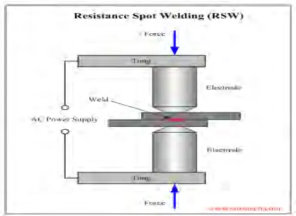
This chapter explain briefly about importance of Resistance Spot Welding (RSW) including on how it works and effect in automotive industry. In addition, objective and project scope also had been done in this chapter.
1.1 Background of Project
Resistance spot welding (RSW) is a popular welding process due to its high speed and low cost combination. It also provides excellent reproducibility. In electronics, biomedical and automotive industries, RSW is one of the metal joining techniques for high volume production (Singh & Suman, 2013). It is one of the efficient and cleanest welding for fabrication sheet metal.
Figure 1.1 : Simple Drawing of RSW (Sahota et al., 2013)
Resistance spot welding is a welding process where the assembly of work part is produced by electrode pressure and heat obtain from resistance with the flow of electric current. The shape and size of weld formed are depends on the shape and size of the electrodes (Sahota et al., 2013).
1.2 Problem Statement
To meet the challenges in the today’s automobile requirements, such as durability and reliability. Resistance spot welding been widely used automotive, aerospace and other industrial area and it is also is an important branch of the welding subject (Chen, Sun, Jiang, Qi, & Zeng, 2016). Recently, it is used largely and gain attention from variety industries such as the automotive industry due to many advantages on it such as low cost, small deformation and high efficiency. Material play an important role in an automotive body in white. It has been observed as a result of increasing requirements of passenger safety, vehicle performance and fuel economy. The response of steel industry to the new challenges is a rapid development of higher strength steels, named Advanced High Strength Steels (AHSS). (Kuziak, Kawalla, & Waengler, 2008)
AHSS offer the excellent properties of potential in improving the vehicle crash performance without extraweight increase. To date, for different structural parts of a vehicle, 85% of AHSS approximately have been used and it could lead up to a weight reduction to 25% compared with a previous model (Liu, Zheng, He, Wang, & Wei, 2016). AHSS is applied in the automotive industry because of its strength safety and lightweight compared to another steel. Due to lightweight itself, the consumption of fuel is automatically reduced
In addition, reliability of resistance spot weld is important due to impact safety standards. When designing vehicle structures, their 'deep collapse' behaviour, where displacements may exceed the wall thickness by several orders of magnitude is very important aspect. Not only the maximum strength and initial instability is necessary. For the same time these structures must meet other criteria like production, functional, time-to-market, and cost criteria, which lay additional constraints on the manufacturing and development process. (Structures, 1998)
One of the quality requirement of spot weld is the nugget diameter. It is important due to strength requirements of the resistance spot welded joints, and associated car body structural integrity. It was reported forming of nugget on the workpiece plays a crucial role in structure joining (Y. Luo, Rui, Xie, & Zhu, 2016). Weld nugget formation is a balance between heat generation and heat dissipation. It has been experimentally observed that in the case of two thickness resistance spot welds, initial heat generation and weld nugget formation occurs where the resistance to the flow of current was the greatest (M Pouranvari & Marashi, 2012).
1.3 Objective
The main objectives of this project are: -
1. To compare the mechanical properties of 2-layer spot welding using different welding parameters
2. To investigate the quality of spot weld in different welding parameters
1.4 Project Scope
This research is subjected to the following scope: -
1. Comparing welding hardness using Microhardness Testing Machine 2. Comparing the tensile strength of different welding parameters using
Universal Testing Machine (UTM)
3. Analyzing microstructure of welding between Advance High Strength Steel (AHSS) and cold roll steel (SPCC) using Scanning Electron Microscopy (SEM)
CHAPTER 2
LITERATURE REVIEW
2.0 Introduction
This chapter explain about resistance welding machine, resistance spot weld machine, parameters of spot weld machine, nugget formation, failure modes, microstructures and types of material use.
2.1 Resistance Welding Machine
Resistance welding is a technology that used in various industries for joining metal sheets together. Resistance welding is a thermo-electric process in which heat is generated at the interface of the parts to be joined by passing an electrical current through the parts for a precisely controlled time and under a controlled force (Amada Miyachi America, 2013). The weld is made by generating heat through current at the metal sheets. The formation of the welding that’s called ‘nugget’ is using electrode with right amount of force, current and time. Resistance welding machine can be classified into several type according to its shape of work pieces and form of electrodes: -
i. Resistance Projection Welding
ii. Resistance Seam Welding
iii. Resistance Butt Welding
2.1.1. Resistance Projection Welding
[image:22.595.188.472.282.427.2]Resistance projection welding is resistance welding process in joining two sheets metal by embossing the projection on the surface by specially design electrode to fit the shapes of work pieces. Heat is produced by both electrodes at the same time. High generation of heat and current are localized at the electrodes that have contacts with work pieces. The electrodes are designed flat and big and usually made from copper based alloys. Figure 2.1 below shows how the process of this welding happen.
Figure 2.1: Projection Welding Process
(Source:
<http://www.mechscience.com/projection-welding-projection-welding-machine-resistance-projection-welding-rpw/> 24/09/15)
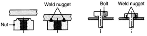
Resistance spot weld equipment can be used for this type of welding
by changing the electrodes. Nuts and bolts can be welded to sheets and plates
by this process. Figure 2.2 below shows how projection welding happen in nuts and bolts. Projection welding widely used in construction industries, electric and electronic.
Figure 2.2: Projection Welding in Nut and Bolts
(Source:
[image:22.595.197.453.617.680.2]2.1.2. Resistance Seam Welding
[image:23.595.206.438.252.416.2]Resistance seam welding is a welding process that joining metal sheets in continuous using two circular rotating electrode wheels. Electric current generate heat that flow through contact area and pressure to joining metal sheets by directly applying opposing force and produce a leak tight weld. A continuous overlapping nugget is formed by this process. Figure 2.3 below shows the process of seam welding.
Figure 2.3: Seam Welding Process
(Source:<http://www.substech.com/dokuwiki/doku.php?id=resistance_welding_rw>
01/06/12)
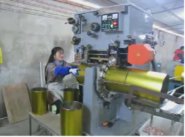
Resistance Seam Welding is high speed and clean process. It is applying when continuous tight weld required for example like manufacturing of containers, drums, fuel tanks and radiator. Figure 2.4 below shows the example how containers was made from seam welding machine.
Figure 2.4: Seam Welding Machine Used in Making Container (Source:
[image:23.595.227.415.556.695.2]2.1.3. Resistance Butt Welding
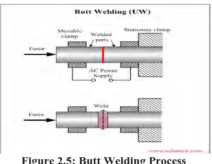
Resistance butt welding is a welding process that joining thick metal
[image:24.595.212.430.258.427.2]plates or bars which one bar is hold on fixed clamp and the other in moving clamp. The two bars are brought together and held simultaneously under a pressure and heated by an electric current passing through the contact area and producing a weld. After the bars was welded, the clamp will release the bar. Figure 2.5 below show how butt welding works.
Figure 2.5: Butt Welding Process
(Source:<http://www.substech.com/dokuwiki/doku.php?id=resistance_welding_rw>
01/06/12)
[image:24.595.212.430.577.697.2]Resistance butt welding used for welding small parts. It is very productive and clean process. This type of welding also provides joining without losing any welded material. Resistance butt welding applied in manufacturing of wheel rims, weld pipes, wire joint and railway track joint. Figure 2.6 below shows diagram on how butt welding works.
Figure 2.6: Butt Welding Diagram Process
(Source: