UNIVERSITI TEKNIKAL MALAYSIA MELAKA
PERFORMANCE ANALYSIS OF OIL SKIMMER FOR GREASE
TRAP SYSTEM TO SHORTEN THE RETENTION TIME
This report is submitted in accordance with the requirement of the Universiti Teknikal Malaysia Melaka (UTeM) for the Bachelor of Mechanical Engineering
Technology (Maintenance) with Honours.
by
NURUL SHAFIQAH BINTI OMAR B071410072
920325105890
UNIVERSITI TEKNIKAL MALAYSIA MELAKA
BORANG PENGESAHAN STATUS LAPORAN PROJEK SARJANA MUDA
TAJUK: PERFORMANCE ANALYSIS OF OIL SKIMMER FOR GREASE TRAP SYSTEM TO SHORTEN THE RETENTION TIME
SESI PENGAJIAN: 2017/18 Semester 1
Saya NURUL SHAFIQAH BINTI OMAR
mengaku membenarkan Laporan PSM ini disimpan di Perpustakaan Universiti Teknikal Malaysia Melaka (UTeM) dengan syarat-syarat kegunaan seperti berikut:
1. Laporan PSM adalah hak milik Universiti Teknikal Malaysia Melaka dan penulis. 2. Perpustakaan Universiti Teknikal Malaysia Melaka dibenarkan membuat salinan untuk
tujuan pengajian sahaja dengan izin penulis.
3. Perpustakaan dibenarkan membuat salinan laporan PSM ini sebagai bahan pertukaran antara institusi pengajian tinggi.
4. **Sila tandakan ( )
SULIT
TERHAD
TIDAK TERHAD
(Mengandungi maklumat yang berdarjah keselamatan atau kepentingan Malaysia sebagaimana yang termaktub dalam AKTA RAHSIA RASMI 1972)
(Mengandungi maklumat TERHAD yang telah ditentukan oleh organisasi/badan di mana penyelidikan dijalankan)
Alamat Tetap:
NO. 34 Jalan Semilang 12,
Taman Sri Putra, Banting 42700
Selangor
Tarikh: ________________________
Disahkan oleh:
Cop Rasmi:
Tarikh: _______________________
DECLARATION
I hereby, declared this report entitled “performance analysis of oil skimmer for grease trap system to shorten the retention time” is the results of my own research except as
cited in references.
Signature : ……….
Author’s Name : ………
APPROVAL
This report is submitted to the Faculty of Engineering Technology of UTeM as a partial fulfillment of the requirements for the degree of Bachelor of Mechanical Engineering Technology (Maintenance) with Honours. The member of the supervisory is as follow:
i
ABSTRAK
Peningkatan pencemaran air sisa dan sebahagian besar penyumbatan air kumbahan
menyebabkan penyekatan yang terhasil daripada lemak, minyak dan gris. Bilangan
pepejal yang didepositkan dalam pembentungan akan meningkat dan menyebabkan
peningkatan pepejal ke aliran air buangan domestik. Versi automatik perangkap gris yang
berkesan akan mengurangkan masalah ini dan mengelakkan kontaminan lemak, minyak
dan gris dalam sistem pembetung. Pengemulsi juga menjadi masalah kerana apabila
terdapat kesan pengemulsi, proses pemisahan akan lebih perlahan dan masa pengekalan
akan lebih lama. Kecekapan rendah kaedah penyingkiran yang direka untuk tangki
penyingkiran dan perangkap gris dalam loji rawatan adalah kelemahan utama teknik
konvensional yang digunakan untuk mengeluarkan lemak, minyak dan gris. Penyelidikan
mengenai sifat minyak, lemak, menjadi inspirasi objektif yang merancang konsep skimmer
untuk tujuan perangkap minyak yang aktif dan untuk membangunkan prototaip skimmer
minyak untuk perangkap gris. Di samping itu, projek ini menganalisis prestasi skimmer
dengan korelasi kepada masa pengekalan. Empat jenis bahan untuk menganalisis
skimmer, iaitu polipropilena, polietilluetilena, aluminium, dan besi. Bahan ini dipilih
dengan menggunakan metodologi perancangan projek menggunakan House of Quality,
carta Morfologi dan kaedah Pugh dan sifat bahan yang sesuai. Perangkap gris aktif yang
direka bentuk dengan empat jenis bahan untuk skimmer telah dibuat dan dianalisis. Dari
analisis, hasilnya menunjukkan prestasi terbaik bahan skimmer yang digunakan untuk
memerangkap minyak adalah polytherafluoroetylene, yang dikenalpasti melalui masa
yang singkat untuk mengumpul minyak. Projek ini telah menyediakan hasil yang lebih
baik untuk memendekkan masa untuk memerangkap lemak, minyak dan gris sebagai
ii
ABSTRACT
iii
DEDICATION
iv
ACKNOWLEDGEMENT
I wish to thank God for giving me the opportunity to start on my Bachelor Degree and for completing this challenging journey successfully. My gratitude and thanks go to my supervisor, sir Mohamed Saiful Firdaus bin Hussin the support and guidance throughout the journey and the completion of this project.
v
TABLE OF CONTENTS
Abstrak i
Abstract ii
Dedication iii
Acknowledgement iv
Table of Content v
List of Tables ix
List of Figures x
List Abbreviations, Symbols and Nomenclatures xi
CHAPTER 1: INTRODUCTION
1.1 Background 1
1.2 Problem Statements 3
1.3 Objectives 4
1.4 Scope 5
CHAPTER 2: LITERATURE REVIEW
2.1 Grease Trap 6
2.2 Type of Grease Trap 7
2.2.1 Passive Grease Trap 7
2.2.2 Active grease trap (remediation) 8
2.2.3 Active grease trap (automatic device) 8
2.3 Wastewater Characterization 9
2.3.1 FOG in wastewater 9
2.3.2 Understanding FOG in water 10
2.4 Nature of Oil 11
2.5 Understanding of Oil Skimmer 12
vi
2.6.1 Nature of metals 12
2.6.2 Nature of ceramic 13
2.6.3 Nature of polymer 14
2.6.4 Nature of composite 14
2.6.5 Advanced materials 15
2.7 Material Selection for Oil Skimmer 15
2.7.1 Polypropylene 16
2.7.2 Nylon 17
2.7.3 Aluminium 17
2.7.4 Stainless steels 18
2.7.5 Clay 18
2.7.6 Iron 19
2.7.7 Synthetic polyisoprene 20
2.7.8 Polystyrene 21
2.7.9 Glass ceramics 21
2.7.10 Plastic Perspex 22
2.7.11 Polytetrafluoroethylene 22
2.8 Hydrophobic and Hydrophilic surface properties 23
2.9 Contact angle and Wettability 23
2.10 Adhesive and Surface energy 23
2.11 Engineering Design 24
2.11.1 Identifying customer needs 25
2.11.2 House of quality 25
2.11.3 Specification of product design 28
2.11.4 Morphological chart 29
2.11.5 Concept generation 30
2.8.6 Pugh Method 31
2.12 Designing work 34
2.12.1 SOLIDWORKS software 34
2.12.2 AutoCAD software 35
vii
2.12.4 IronCAD 36
2.13 Experimental Works 36
2.13.1 Grease trap prototype machine 36
2.13.2 Material and Apparatus 36
CHAPTER 3: METHODOLOGY
3.1 Introduction 38
3.2 Design Development Process 38
3.3 Project Flow Chart 39
3.4 Conceptualization 42
3.5 Product Architecture & Design Specification 42
3.6 Material Selection 42
3.6.1 Polypropylene 42
3.6.2 Polytetrafluoroethylene 43
3.6.3 Aluminium 43
3.6.4 Iron 44
3.7 House of Quality 45
3.8 Morphology Chart 47
3.9 Data analysis 47
3.10 Expected Result 48
CHAPTER 4: RESULTS
4.1 Overview 51
4.2 Outcome of design development 51
4.2.1House of Quality 51
4.2.2 Selected material 53
4.2.3 Design concept 54
4.3 Concept selection 55
4.4 Product design 55
4.4.1 Morphological chart 56
viii
4.5 Conceptual design 59
4.6 Design operation 59
4.7 Prototype design 60
4.8 Actual prototype 61
4.9 Prototype analysis data 62
4.9.1 Performance analysis of skimmer 62
4.9.2 Effective of retention time of oil 63
4.10 Result discussion 63
CHAPTER 5: CONCLUSION
5.1 Conclusion 64
5.2 Recommendation 64
REFERENCES
ix
LIST OF TABLES
2.1 The example of Morphology Chart 30
3.1 Morphology Chart 47
3.2 Data for Polypropylene skimmer (Skimmer 1) 48 3.3 Data for Polytetrafluoroethylene skimmer (Skimmer 2) 48 3.4 Data for Aluminium skimmer (Skimmer 3) 48
3.5 Data for Iron skimmer (Skimmer 4) 49
3.6 Data for retention time of skimmer materials 49
4.1 Contact Angle with Water for Various Material 54
4.2 Morphological Chart Result 56
4.3 Pugh method 57
4.4 Pugh method with rating 57
4.5 Conceptual design of skimmer 59
4.6 Data for Polytetrafluoroethylene PTFE (skimmer 1) 62
4.7 Data for Polypropylene skimmer (Skimmer 2) 62
4.8 Data for Iron skimmer (Skimmer 3) 62
4.9 Data for Aluminium skimmer (Skimmer 4) 62
x
Figure Title Pages
1.1 The formation of solid waste 4
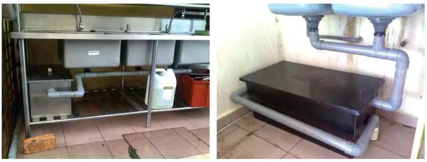
2.1 The example of grease trap under the sink 7
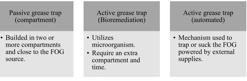
2.2 Types of Grease trap 9
2.3 Surface classifications 24
2.4 The example of House of quality translates the voice of the customer
27
3.1 The flow chart of developing a grease trap system 39
3.2 House of Quality 45
3.3 Example of graph of inserting oil versus collected oil by the different Skimmers material
50
4.1 House of Quality 52
4.2 Prototype design 60
4.3 Prototype design dimension 60
4.4 Prototype of grease trap system 61
4.5 Polypropylene (PP) skimmer 61
4.6 Polytetrafluoroethylene (PTFE) skimmer 61
4.7 Iron (Fe) skimmer 61
4.8 Aluminium(Al) skimmer 61
xi
LIST OF ABBREVIATIONS, SYMBOLS AND
NOMENCLATURE
FOG - Fat, oil and grease HOQ - House of quality GTW - Grease trap waste PTFE - Polytetrafluoroethylene
CA - Contact angle
PDS - Product design specification CAD - Computer aided design
1
CHAPTER 1
INTRODUCTION
1.1 Background
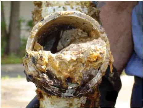
A fast development of a variety restaurants will influence a bad environment by the productivity of wastewater. Untreated restaurant wastewater and direct flow of food waste through the sewer pipe will cause environmental pollution. Besides it blockage in the presence of fats, oil, and grease by the increment of drainage capacity limit. The discharged of (FOG) directly into public sewers may causes an inefficient healthy community sewers performance and delayed the delivery capacity in a sewer, clogging in drain pipes also can be influenced, and producing a hard particles deposits due to chemical (reaction) and physical (aggregation) processes (Long et al., 2012) and unpleasant odours and corrosion of sewer lines due to anaerobic reactions.
2
Oil trap or oil interceptors have been utilized since Victorian period (1837) and it is a pipe component proposed to skim or trap FOG before they enter a wastewater pipes system. Grease trap waste (GTW) from a grease trap often installed inside the food service premises has become a significant stream of organic waste in municipal areas. The direct drainage into the collection of sewer system is also illegal in most municipalities because it can contribute accumulate on pipe walls, and potentially form hardened deposits through a physical aggregation or a chemical reaction process (He et al., 2011).
The conventional techniques found by abstract oil and grease utilizing skimming tanks and oil and grease traps in treatment plants but the main disadvantage of these methods is their low efficiency of abstraction. Altogether sort of grease trap regularly uses the similar physics where densities show a vibrant character where the grease is lighter than water and drive rise to the upper once the mixture is allowable to settle for some time (also called retention time) (Nidzamuddin et al., 2015). However, a grease trap which designed to hold the grease within its separation chamber/compartment constantly reducing its working volume and hence its ability to allow separation required retention time will reduce (Aziz, 2010). This will decrease the productivity of the oil and more FOG will go through the oil trap then flow into the waste water sewer pipes system.
3
trap has slower period to progression then it frequently be influenced by the gravitational act to work and an active grease trap has littler progression to trap the FOG and fitted out with convinced tools that implicate the procedure of external power source (Nidzamuddin et al., 2015). The concept developed for this device is innovated from analysing various passive grease traps. The passive grease trap is relatively cheaper in production cost and simpler in construction and concept. Unfortunately, it has a longer time to process since it usually depends on the gravitational law to operate (Middleton et al., 1995). On the other hand, an active grease trap is more often than not is equipped with certain mechanisms that require the usage of the external alternating current power source. The mechanisms are usually employed to separate the FOG from the wastewater, and such examples are gravity, microorganism, heater, and skimmer or pump (Batten et al., 2009).
1.2 Problem Statement
Recent change in waste water pollution increase and the most of the sewage water blockage caused blocking resulting from the present of FOG. FOG comes from cooking oil, animal fats, and cools and solidifies at normal temperatures in pipes and blockages can form in the sewer pipes, eventually causing backups in the collection system.A spillage of big oil accidents into water cause a huge impact to the environment. Apart of this, sometimes in the use of oil industries and oil products getting spillage through caused by the results of chronic and careless habits (Patel, 2015).
4
[image:19.612.211.443.243.418.2]problems may not just occur with the clogging of sewers but also the pumping plants and the interference of biological treatment processes. An effective automated version of grease trap will reduce this problem and avoid the FOG contaminant in the sewer system. In addition, the emulsifier is also a problem because when there is an emulsifier effect in the FOG, separation process will be slower and retention time will be longer (Aziz, 2010). Low efficiency of removal methods designed for skimming tank and grease trap in treatment plants is the main disadvantage of conventional techniques used to remove FOG.
Figure 1.1 the formation of solid waste
The clogging of sewer system caused by the remaining FOG needs to be clean and sometimes replaces because these may lead the increasing of maintenance and inspection cost.
5
and design of the skimmer. Consequently, there is a need to abbreviate the retention time by developing a best material oil skimmer.
1.3 Objectives
The objectives of this study are:
1. To design the concept of oil skimmer for grease trap 2. To develop prototype of oil skimmer for grease trap
3. To analyze the skimmer performance with correlation to retention time
1.4 Scope
6
CHAPTER 2
LITERATURE REVIEW
2.1 Grease trap
Grease trap or called oil interceptor, oil recuperation gadget and oil converter is a pipes gadget intended to capture most oils and solids before they enter a wastewater transfer disposal system. Normal wastewater contains little measures of oils which go into septic tanks and treatment offices to frame a floating scum layer. This scum layer is very slowly digested and produced by microorganisms in the anaerobic digestion process. A lot of oil from nourishment planning amounts of oil from food preparation in restaurants can form a severe flood on a septic tank or treatment facility, causing the release of untreated sewage into the environment. High-thickness fats and cooking oil such as fat set when cooled, and can combine with other disposed solids to clog drain pipes.
7
Figure 2.1 the example of grease trap under the sink
2.2 Type of grease trap
2.2.1 Passive Grease Trap
A passive grease trap is the pipe assembly containing a decomposition of waste. Fats, oils, and grease (FOG) is lighter than water and floats on the top surface of the water in the tank. A passive grease trap is often built on the ground outside a kitchen or under the sink. It usually made up of two or three sections of separation part and is filled with cold water.
8
grease naturally by the gravitational trap. The oil trap innovation process of mixed water with FOG from inlet from sink flowing through divider section and FOG isolate itself from the water.
2.2.2 Active grease trap (remediation)
An Active Grease Traps is an installed metal or plastic tank that is used in the food service offices to overcome the fat, oil and grease from entering sewer septic sterile or framework. Bioremediation grease trap is a use of a trap to deactivate microorganisms and digest fat trapped and converting it to soluble liquid, the liquid biodegradable safe to be drained into the sewage system. Grease trap is also accompanied by a full bioreactor with the enzyme such as Candida rugosa and Pseudomonas cepacian (Oya, 2007), (Ozama, 1999). Furthermore, the grease trap compartment and bioremediation require the addition of approximately (2-5 hours) to the digestive process occurs. In other words the bioremediation automatically and continuously pre-activates, grows and optimizes the physiological condition and digest grease and sludge to reduce causes of noxious/toxic odors, prior to injection into the wastewater.
2.2.3 Active grease trap (automatic device)
9
[image:24.612.121.550.160.302.2]arrival. In another word, this type of grease trap used (grease recovery devices) to removes the grease automatically when trapped.
Figure 2.2 Types of Grease trap
2.3 Wastewater Characterization
Human activity of production waste is unavoidable and part of this waste will end up significantly as a wastewater. Wastewater quantity and quality can be determined by many factors. The producing amount of waste for all human and industries are not the same, this amount and type of wastewater usually influence the behavior, lifestyle, and standard of living of the inhabitants by people surrounded (Henze et al., 2008). In restaurant and households, mostly produce by solid and liquid waste and it can be possible to change the amount of the waste quantity. There's no exception for industry to produce a large amount of wastewater.
2.3.1 FOG in wastewater
Wastewater produced from in commercial food service facilities are different with residential wastewater and it will increase the volume during busy Passive grease trap
(compartment)
• Builded in two or more compartments and close to the FOG source.
Active grease trap (Bioremediation)
• Utilizes
microorganism. • Require an extra
compartment and time.
Active grease trap (automated)