i
UNIVERSITI TEKNIKAL MALAYSIA MELAKA
INVESTIGATION OF SURFACE INTEGRITY WHEN
MACHINING AISI 1045 USING UNCOATED CARBIDE
CUTTING TOOLS
This report submitted in accordance with requirement of the Universiti Teknikal Malaysia Melaka (UTeM) for the Bachelor Degree of Manufacturing Engineering
(Manufacturing Process) (Hons.)
by
SITI NUR RAHEENA BINTI HAMDAN
B051210115
931004-14-5852
ii
DECLARATION
I hereby, declared this report entitled “Investigation of Surface Integrity When
Machining AISI 1045 Using Uncoated Carbide Cutting Tools” is the results of my own research except as cited in references.
Signature : ………
Author’s Name : SITI NUR RAHEENA BINTI HAMDAN
iii
APPROVAL
This report is submitted to the Faculty of Manufacturing Engineering of UTeM as a partial fulfillment of the requirements for the degree of Bachelor of Manufacturing Engineering (Manufacturing Process) (Hons.). The member of the supervisory is as follow:
………
i
ABSTRAK
ii
ABSTRACT
iii
DEDICATION
iv
ACKNOWLEGDEMENT
First and foremost, I would like to express my greatest gratitude to Almighty God for giving me strength and courage to finally complete my bachelor degree project with the best I could. Indeed, without His Help and Well, nothing will be accomplished.
My deep and sincere gratitude goes to my most respected supervisor, Dr. Mohd Hadzley bin Abu Bakar, for his continuous guidance, stimulating encouragement and valuable suggestions in completing this project. In addition to Dr. Umar, En. Nor Fauzi, Syahida and Zahra for data sharing in this project.
v
TABLE OF CONTENT
Abstrak i
Abstract ii
Dedication iii
Acknowlegdement iv
CHAPTER 1
1
1.1Background of Study 1
1.2 Problem Statement 4
1.3 Objective 5
1.4 Scope 5
CHAPTER 2
6
2.1 Steel 6
2.1.1 Carbon Steel or Plain Carbon Steel 7
2.2 AISI 1045 – Medium Carbon Steel 8
2.2.1 Chemical Composition 8
2.2.2 Mechanical Properties 9
2.3 Machining 10
2.3.1 Machining Element 10
2.4 CNC Lathe Machine 11
2.4.1 CNC Lathe Components 12
2.4.2 Turning Process 14
2.4.3 Cutting Process 15
2.5 Turning Process Parameter 16
2.5.1 Tool Geometry 17
2.5.2 Material-removal Rate 18
2.5.3 Cutting Speed 19
2.5.4 Spindle Speed 20
2.5.5 Feed Rate 20
vi
2.6 Chip Formation 21
2.7 Selection Cutting Tool 22
2.7.1 Cutting Tools Materials 24
2.8 Cutting Fluids 24
2.8.1 Purpose Cutting Fluids 24
2.9 Surface Integrity 25
2.9.1 Surface Roughness 25
2.9.2 Surface Profile 27
CHAPTER 3
28
3.1 Flow Chart 29
3.2 Material Selection 31
3.3 Cutting Tool 32
3.4 Process Parameters 33
3.5 Machining and Equipment 34
3.5.1 CNC Lathe Machine 34
3.5.2 Step in Turning Operation 35
3.6 Sample Preparation – EDM Wire Cut 38
3.7 Data Analysis 38
3.7.1 Surface Roughness Tester 39
3.7.2 Stereo Microscope 41
3.7.3 Scanning Electron Microscope 42
CHAPTER 4
44
4.1 Surface Roughness 44
4.2 Surface Roughness Data and Graph Analysis 45
4.2.1 Wet Cutting Condition 45
4.2.2 Dry Cutting Condition 48
4.2.3 Comparison dry and wet cutting condition 51
4.3 Surface Profile 54
CHAPTER 5
58
5.1 Conclusion 58
5.2 Recommendations 59
5.3 Sustainable Development 60
REFERENCES
62
viii
LIST OF TABLES
2.1 Chemical Composition of AISI 1045 8
2.2 Mechanical Properties of AISI 1045 9
2.3 Primary Element of Machining 10
2.4 Formula for Turning Parameters 19
3.1 Properties of AISI 1045 Steel 32
3.2 The Information about Carbide Inserts 32
3.3 Experiment Parameters 33
3.4 CNC Lathe Machine Specification 35
3.5 General specification of surface roughness tester 39
3.6 General information for stereo microscope 41
ix 4.1 Wet cutting with various cutting speed for feed rate 0.15 mm/rev 45
4.2 Wet cutting with various cutting speed for feed rate 0.50 mm/rev 47
4.3 Dry cutting with various cutting speed for feed rate 0.15 mm/rev 48
4.4 Dry cutting with various cutting speed for feed rate 0.50 mm/rev 50
4.5 Data of surface roughness, Ra at dry and wet (Feed Rate 0.15mm/rev) 51
4.6 Data of surface roughness, Ra at dry and wet (Feed Rate 0.50mm/rev) 52
4.7 Surface profile for feed rate 0.15 mm/rev at dry and wet condition 54
x
LIST OF FIGURES
2.1 Machining by cutting 11
2.2 CNC Lathe machine in the industry 12
2.3 Component of lathe machine 12
2.4 Various cutting operations of lathe machine 16
2.5 General recommendation for tools angles in turning 18
2.6 Type of Chips Formation 21
2.7 Coordinates used for surface roughness measurement 26
3.1 Flow Chart of Project Planning 29
3.2 The AISI 1045 Steel Bar 31
3.3 Carbide Insert 32
3.4 CNC Lathe Machine DMG Mori Seiki CTX 310 ecoline 34
3.5 Centre drilling Process 36
3.6 Clamped workpiece 36
3.7 CNC turning process using DMG Mori Seiki CTX 310 ecoline turning
machine. 37
3.8 Wire Cut Electrical Discharge Machining (EDM) 38
3.9 Surface roughness tester of Mitutoyo Surftest SJ-401. 39
xi
3.11 Meiji Stereo Microscopes type EMZ 41
3.12 Zeiss SEM type Evo 50 Series 42
4.1 Surface Roughness,Ra (µm) Versus Speed (m/min) for wet cutting condition
with feed rate 0.15mm/rev 46
4.2 Surface Roughness,Ra (µm) Versus Speed (m/min) for wet cutting condition
with feedrate 0.5mm/rev 47
4.3 Surface Roughness,Ra (µm) Versus Speed (m/min) for dry cutting condition
with feedrate 0.15mm/rev 49
4.4 Surface Roughness,Ra (µm) Versus Speed (m/min) for dry cutting condition
with feedrate 0.5mm/rev 50
4.5 Graph comparison of surface roughness,Ra vs speed
(FeedRate 0.15mm/rev) 52
4.6 Graph comparison of surface roughness, Ra vs speed
13 ``
CHAPTER 1
INTRODUCTION
This section explains about background, objective and scope of the study. Background discusses about the type of material used, CNC lathe machine and performances of machining that need to analyse. While the objective mentions about the mission that needed to be achieved for this project and scope covers everything what is supposed to do in this project.
1.1 Background of Study
14 One of the materials that commonly used in the industry is steel. The important of steel widely used nowadays around the world in industry sector, including aerospace, automotive, aircraft and chemical. In a group of steels, there are two types of steels which are plain carbon steel and alloy steels. In this study, materials used is AISI 1045 which classified into plain carbon steels. Plain carbon steel is the one in which the only alloying element is carbon. Carbon being a powerful alloying agent can present a kind of strength and hardness by varying its composition in the steel. It is in this regard that carbon steels are branched into three main groups that are low-carbon steel, medium-carbon steel and high-medium-carbon steel (Larry Horath, 2011). AISI 1045 contain medium-carbon composition between 0.43% - 0.50%, which its fall under group medium-carbon steel. It has good mechanical properties such as good machinability, high strength, and high hardness. In recent years, there has been an increasing curiosity in research of machinability AISI 1045 that concentrate to reduce manufacturing cost and increase productivity (Kishawy et al, 2009).
In sector industry, turning is the most common process use and is an engineering machining process which is used to produce rotational parts by cutting away unwanted material. Turning can be done manually, in a traditional form called as lathe, which frequently requires continuous supervision by the operator. Nowadays, the industrial sector is increasing with the new technologies which are use automated system called as computer numerical control, better known as CNC. By using CNC machining, the process is more precise than manual machining, and can be repeated in exactly the same manner over and over again. In this process, it is vital to select input (cutting) parameters with great precision for achieving high cutting performance (A. Qasim et al, 2015).
15 the surface roughness is important things that should be consider. To produce a better quality product in industry, the value of surface roughness must be lower (Gupta & Kumar, 2015). For that reason, a study of surface roughness is important in order to relate the condition of the machined surface with respected parameter.
There are two conditions in machining which is dry and wet. Dry machining is a process where cutting fluid will not be used when doing machining process. Advantage dry machining is to reduce the use of fluid that probably can reduce cost as well as to reduce impact hazard to the environment. Dry cutting normally employs for finishing process to gray cast iron or powder base material. On the other hand, wet cutting is process where fluid is applied in machining environment to provide cooling and lubrication. This process enables to produces longer tool life and fine surface finish. However, the use of fluid in machining may produce some disadvantages such as hazard to the environment, effect to machinist skin and increase cost machining. Therefore, as the both dry and wet cutting provide a certain advantage and disadvantage the comparison study for this two processes must be conducted in order to determine which process is suitable in machining particular material.
16
1.2 Problem Statement
17
1.3 Objectives
The objectives of this study are:
i. To study the effect of cutting speed on surface roughness during machining AISI 1045 at dry and wet conditions.
ii. To observe surface profile based on machining AISI 1045 at dry and wet conditions.
iii. To compare the surface integrity of AISI 1045 at dry and wet conditions.
1.4 Scope
18
CHAPTER 2
LITERATURE REVIEW
The literature review part consists of the summarizing of the project in order to get the whole data about workpiece material, cutting tools and lathe machine information, this will give an idea to run the project. This chapter presents related study done by previous research and will be working as a reference, to give information and guide base on journal, book and other source on the internet that could contribute to this project.
2.1 Steel
19 2.1.1 Carbon Steel or Plain Carbon Steel
Plain carbon steel is a mixture of iron and carbon with low quantities of manganese, silicon, sulfur and phosphorous. The primary aim of these alloying elements is not to alter the mechanical properties of the steel. The carbon content may vary in the range from a trace to 1.7%, although rarely over 1.3%. Plain carbon steels containing more than 1.3% carbon are seldom produced or used (Larry Horath, 2011).
Plain carbon steels are divided into three groups, according to carbon content, as follows:
Low carbon steel
Called as mild steel, it has carbon content less than 0.30%. It possesses good formability and weldability but lacks hardness. The structures of such steels are usually ferrite and pearlite. It is used in making bolts, nuts, sheets, plates, tubes and machine components that do not require high strength.
Medium carbon steel
The carbon composition is in the range 0.30 % to 0.60%. It has higher strength than low-carbon steels. The increasing carbon content makes them harder. These steels are extremely popular, because the properties of such steels are greatly improved by heat treating and therefore they are best adapted for machine parts such as gears, axles, connecting rods, crank shafts, railroad equipment, and parts for metal working machinery.
High carbon steel
20
2.2 AISI 1045-Medium Carbon Steel
AISI 1045 has classified under types of medium carbon steel according to the carbon composition. AISI 1045 is characterized by good weldability, good machinability, and high strength and impact properties in either the normalized or hot rolled condition. AISI 1045 is one of the material widely used in the industry nowadays because of its capability that easily can be made in mold, template, mortise pin, column. This kind of steel has good mechanical property, is broadly used in structural parts which may support stress alternation, especially made into some connecting rods, bolts, wheel gear and shaft parts (Nunura et al., 2015). The machinability of AISI 1045 varies with its microstructure and hardness due to the carbon composition inside the material itself.
2.2.1 Chemical Composition
The chemical composition of the AISI 1045 is shown in the Table 2.1:
Table 2.1: Chemical Composition of AISI 1045
(Source:http://www.azom.com/article.aspx?ArticleID=6130>17/09/15)
Element Content
Carbon, C 0.420 - 0.50 %
Iron, Fe 98.51 - 98.98 %
Manganese, Mn 0.60 - 0.90 %
Phosphorous, P ≤ 0.040 %
21 2.2.2 Mechanical Properties
[image:24.595.105.527.188.538.2]The mechanical properties of the AISI 1045 is shown in the Table 2.2:
Table 2.2: Mechanical Properties of AISI 1045
(Source:http://www.azom.com/article.aspx?ArticleID=6130>17/09/15)
Mechanical Properties Metric Imperial
Hardness, Brinell 163 163
Hardness, Knoop (Converted from Brinell hardness) 184 184
Hardness, Rockwell B (Converted from Brinell hardness)
84 84
Hardness, Vickers (Converted from Brinell hardness) 170 170
Tensile Strength, Ultimate 565 MPa 81900 psi
Tensile Strength, Yield 310 MPa 45000 psi
Elongation at Break (in 50 mm) 16.0 % 16.0 %
Reduction of Area 40.0 % 40.0 %
Modulus of Elasticity (Typical for steel) 200 GPa 29000 ksi
Bulk Modulus (Typical for steel) 140 GPa 20300 ksi
22 2.3 Machining
Machining processes is defined by metal parts are shaped by removal of unwanted materials (Cheng, 2012). Over a year manufacturing industry has become one of most growth industries this day. Many manufactured products required machining at some of their stage production. Machining can be defined as the removal of unwanted material from the work piece into a finish product of the desired shape, size and surface quality. According to El-Hofy (2011), the evolution of new cutting tool material opened a new evolution for the machining industry where machine tool development took place. There are several classifications of machining process, one of it is machining by cutting and the common process is turning, cutting off, slab milling and end milling.
2.3.1 Machining Element
There are several main elements that are required for a machining process completed shown in Table 2.3 (Kalpakjian & Schmid, 2013). Figure 2.1 shows the mechanism of cutting during machining process.
Table 2.3: Primary element of machining (Source: Kalpakjian & Schmid, 2013)
Workpiece Its shape and size for continuous and intermittent cutting, the chemical composition, mechanical properties and
metallurgical properties.
Tool Material and geometry
Chip Types of chips and their geometry
23
Figure 2.1: Machining by cutting (Kalpakjian & Schmid, 2013)
2.4 CNC Lathe Machine
24
Figure 2.2: CNC lathe machine in the industry. (Source: Helman CNC, 2011)
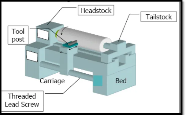
2.4.1 CNC Lathe Components
[image:27.595.168.472.467.656.2]Lathes are equipped with a variety of components and accessories such as bed, carriage, headstock, and tailstock as shown in Figure 2.3.
Figure 2.3: Component of lathe machine
25 a) Bed
Bed is the base of lathe machine because it supports all major components in the lathe. The bed is built rigid and made from grey or nodular cast iron. The main features of beds construction are the ways in which formed at the top portion besides run the full length of the bed.
b) Headstock
The headstock is permanent to the bed and it equipped with motors, pulley, and belts. It rotates the workpiece by using a chuck. It driven by an electric motor connected either to a belt or pulley system or to a geared system. The speed can be set manually through controlled selector or by electrical control. For long bars or tubing workpiece, holding device such as chuck and collets is used with headstock for various turning operations.
c) Tailstock
The tailstock is placed at the opposite end of the lathe from the headstock. Tailstock can be clamped in any position and can slide along the ways and support the other end of the workpiece.
d) Carriage
The carriage consists of apron, saddle, compound rest, cross slide and tool post that slides along the ways. Carriage is used to move and carry the cutting tool. The cutting tool is attached on the tool post. The cross slide moves radially in and out controlling the radial position of the cutting tool. The apron is equipped with mechanism for both manual and mechanized movement of the carriage and the cross slide by means of the lead screw.
e) Lead Screw and Feed Rod
26 2.4.2 Turning Process
Turning is a method of machining by cutting the workpiece carried out the main rotary motion while the tool performs the linear motion. There are two types of motion in turning which is primary motion and auxiliary motion. Major motion is the rotary motion of the workpiece around the turning axis, while auxiliary motion is feed motion or the linear motion of the tool (Helmi and El-Hofy, 2011). Turning processes can be categorized according to the direction of tool feed. There are three common types in turning processes. First is straight turning, happens when the direction of the feed motion is parallel to the turning axis. Second taper turning, which is occurring when the direction of the tool feed motion intersects with the turning axis. Lastly is transverse turning, this type of turning occurring when the direction of the tool feed motion is perpendicular to the turning axis. This type of turning can be divided into radial and facing turning.
27 2.4.3 Cutting Process
Lathe machine is capable to operate several machining operations. Figure 2.4 shows a various operation that is performed by lathe machine. Lathe machine is known widely as versatile machine that capable to produce various cutting shapes and process.
Lathe machine is capable to operate several machining operations such as
Turning – a process that produces straight conical, curved, or grooved
workpiece
Facing – Cutting on perpendicular to its axis and produce a flat surface on the
part
Cutting with form tool – form tool is used to produce various axis symmetric
shapes for functional or aesthetic purposes.
Boring – To enlarge an existing hole that has been produced by previous
process and to produce internal grooves
Drilling – To produce new hole
Cutting off – To cut the workpiece
Threading – To produce external and internal threads
28
Figure 2.4: Various cutting operations that can be made by lathe machine
(Kalpakjian & Schmid, 2013)
2.5 Turning Process Parameter
29 2.5.1 Tool Geometry
The various angles in a single-point cutting tool plays an important function im machining operation (Kalpakjian & Schmid, 2013). These angles are measured in a coordinate system consisting of the three major axes of the tool shank. Nonetheless, these angles may be dissimilar, with regard to the workpiece, after the tool is mounted in the tool holder. There are about five types of angle influence in tool geometry.
a) Rake angle – It is significant in holding both the way of chip flow and the strength of the tool tip. Positive rake angles can improve the cutting operation by reducing forces and temperatures.Nevertheless, positive angles also result in a small included angle of the tool tip possibly leading to premature tool chipping and failure, depending on the toughness of the tool material.
b) Side rake angle – Side rake angle are more important than the back rake angle and it generally controls the direction of chip flow and. Common angle for machining carbide inserts are in the range from -5° to 5°.
c) Cutting edge angle – Cutting force, chip formation and tool strength usually affected by this angle.
d) Relief angle - Controls interference and rubbing at the tool workpiece interface. If it is excessively large, the tool tip may chip off; if it is excessively small, flank wear may be excessive.
30 Figure 2.5 shown are recommended tool geometry for turning process for various workpiece materials
Figure 2.5: General Recommendations for Tool Angles in Turning
(Kalpakjian & Schmid, 2013)
2.5.2 Material-Removal Rate
In turning process material removal rate can be defined as the volume of material removed per unit time with the unit of mm3/min. Table 2.4 below show the formula for turning parameters. To calculate the material removal rate (MRR) is using the formula below:
MRR = πDavgdfN Eq 1
Where,
Davg = D0+ Df
2 Eq 2
It also can be,
MRR = dfV Eq3
Where,
t =
131
Table 2.4: Formula for turning parameters (Kalpakjian & Schmid, 2013)
2.5.3 Cutting Speed
Cutting speed can be defined by the rate at which a point on the circumference of the workpiece move passed the cutting tool. Cutting speed is expressed in meters per minute (m/min). Magd et al, (2002) mentions to get better production rate and cutting tool life, cutting speed must be determined by cutting tools and metal manufacture.
V = πDN Eq 5
Where,
V = Cutting speed (m/min)
D = Diameter of the workpiece (m) N = rotational speed of workpiece (rpm)
Symbol Description
N Rotational speed of workpiece, rpm f Feed, mm/rev
υ Feed rate or linear speed of the tool along workpiece length, mm/min
V Surface speed of workpiece, m/min L Length of cut, mm
Do Original diameter of workpiece, mm
Df Final diameter of workpiece, mm
Davg Average diameter of workpiece, mm
32 2.5.4 Spindle Speed
The diameter of the work and the cutting speed of the material must be known in order to calculate the number of revolutions per minute. The formula for calculating the spindle speed is:
r/min =
V ×320D Eq6
Where,
V = cutting speed (m/min) D = diameter of workpiece (mm)
2.5.5 Feed Rate
The feed rate is defined as the cutting tool to advance alongside the length of the work for every revolution of the spindle. For example, if the lathe is set for a 0.20 mm feed, the cutting tool will travel along the length of work which is 0.20 mm for every complete turn of the workpiece. There only two cuts should be taken to bring diameter to size which is roughing cut and a finishing cut.
2.5.6 Depth of Cut
Depth of cut (d) is the distance of cutting tool penetrates into the workpiece. The depth of cut is essentially self-explanatory. According to Molian (2006), the diameter of the workpiece is reduced by two times the depth of cut because this layer is being removed from both sides of the work. In turning depth of cut can be calculated as:
d = D0+ Df
2 Eq 7
33 Do = Original workpiece diameter (mm)
Df = Final workpiece diameter (mm)
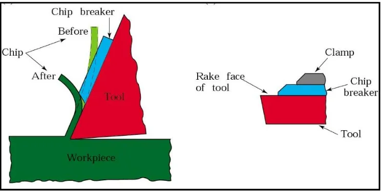
2.6 Chip Formation
[image:36.595.174.463.401.587.2]Chip formation depends on the workpiece material and the machining condition. Chip formations that are formed will significantly affect the surface roughness and workpiece dimension. During cutting process, there are three types of chips formation can produce. The heat generate during a cutting operation is the summation of plastic deformation involve in chip formation and the friction between tool and work piece and between tool and chip (Khidhir et al, 2009). Tool chips have been classified into three types as shown in Figure 2.6 (Kalpakjian and Schmid, 2009).
34 (a) Continuous chip
Continuous chips are formed with ductile materials at high cutting speeds and high rake angles. Continuous chips tend to become tangled around the tool holder, the fixturing, and the workpiece, as well as chip-disposal system, and the operation has to be stopped to clear away the chips. This problem can be alleviated with chip breakers and by changing machining parameters, such as cutting speed, feed, and cutting fluids.
(b) Discontinuous chip
Discontinuous chips consist of segments that may be firmly or loosely attached to each other. It normally obtained in cutting ductile materials and provides good surface finish.
(c) Build-up edge chip (BUE)
A built-up edge (BUE), consisting of layers of material from the workpiece that are gradually deposited on the tool, may form at the tip of the tool during cutting. As it becomes larger, the BUE becomes unstable and eventually breaks up. However, as the cutting speed is increased, the size of the BUE decreases and the surface finish is improved.
2.7 Selection Cutting Tools
35 2.7.1 Cutting Tools Materials
There are many types of cutting material in order to perform the machining process according to the application. Wrong selection cutting tool material will give inappropriate result of machining process, this can produce a problem like shortened tool life, edge chipping and insert breakage are likely if feed rates are too high, whereas when feeds are too low, chip control becomes a problem. The fews type of cutting tools material is:
a) High Carbon Steel
Carbon steel were used for all cutting tools, where their carbon content ranging from 0.80% to 1.2%. These steels have good with heat treatment and hardening properties and with proper heat treatment, attain as great hardness as any high-speed alloys (Kalpakjian and Schmid, 2013).
b) High Speed Steel
Kalpakjian and Schmid (2013) state that high speed steel (HSS) the composition of this material normally consisted of 18% tungsten and 5.5% chromium as the dominant alloying elements. This material has ability to resist softening at high temperatures is known as hot hardness and with adequate quality. Because of their hot hardness ability, this material was used as a cutting tool for machining soft material such an aluminum or Teflon.
c) Carbide
36 d) Diamond
Diamonds used as single-point tools because of their high hardness and brittleness for light cuts and high speed cuts. They are used either for hard materials difficult to cut with other tool materials or for the light cuts on softer materials where accuracy and surface finished are important.
2.8 Cutting Fluids
Main function of cutting fluid is to remove the formation of chips at cutting zone. Hence, the chips will not interfere with further processing. The cutting fluid act as lubricant to avoid chip tool interactions within the flutes. The cutting fluid is effective in cooling and lubricating workpiece (Liu et al., 2009). Its function as reducing friction among the cutting tools, chips and workpiece. According to Sharma (2015) cutting fluid perform the primary function of heat dissipation and lubrication during metal cutting operations. Cutting fluid is important in assist the machining process. Besides that, it is also said to be accounting to major expenditure in any metal cutting industry, in fact more than cost of cutting tool.
2.8.1 Purpose Cutting Fluids
Cutting fluid was used to cool and lubricate both the workpiece and cutting tools edge. In addition, it can improve the machined surface quality and an increase in tool life (Dhar et al, 2006). The main benefits of using cutting fluids are:
(a) Lubrication
37 (b) Surface Quality
Both heat removal and frictional improvement aims in obtaining improved machined component surface texture and integrity.
(c) Tool Life
Heat removal and friction can be reduced during machining operation hence will increases the tool life.
2.9 Surface Integrity
Surface integrity is a term that represents the conditions of characteristics of the workpiece material surface after machining process. It generally can be divided into two aspects which are the external topography of surfaces (surface finish) and the mechanical properties, microstructure and residual stresses beneath the subsurface layers (J. Paulo Davim, 2010). Surface integrity are very important in relation to performance characteristics such as fracture strength, fatigue strength, corrosion rate and tri biological behaviour such as friction, wear and lubrication, and dimensional accuracy According to Davim et al (2010), the term surface integrity is used to describe the attributes of a machined surface and its relationship to functional performance.
2.9.1 Surface Roughness
38 Surface roughness has greatly influences to the manufacturing cost. It consists of the feed marks generated by the machining process. In evaluating the productivity of machine tool and machine parts, the quality of surface is significantly the important factor. Not only in term of tolerances, but a good surface product also reduces the assembly time and avoids the need of secondary operation and leads to cost reduction (Rana and Panchal, 2014).
The arithmetic mean value (Ra) is based on the schematic illustration of a rough surface as shown in Figure 2.7. It is defined as
Ra = 𝑎 + 𝑏 + 𝑐 + 𝑑 + … 𝑛
where all ordinates a, b, c, …, are absolute values and n is the number of readings.
39 2.9.2 Surface Profile
40
CHAPTER 3
METHODOLOGY
41
[image:44.595.198.427.113.679.2]3.1 Flow Chart
42
Figure 3.1: The flowchart of FYP (cont’d)
Dry Cut Condition Wet Cut Condition
Cutting Speed Feed Rate Cutting Speed Feed Rate
Analysis Data- Surface Integrity
Surface Roughness
Surface Profile
Interpret the Result
Discussion and Conclusion
End A
Objective 1
Objective 2
Comparison Objective
43
3.2 Material Selection
Material selection for workpiece and cutting tool is the most important for this experiment because every material has different properties that can be affected from the parameter that was selected. The suitable selection of material is the most significant aspect to take into consideration in processes related to the experiment. From the discussion with the supervisor and literature review, the workpiece that was used in this machining are AISI 1045 which is plain carbon steel and cutting tool are carbide insert with code number is TNMG160404- DM Material that will be used is AISI 1045 a medium carbon steel designed to be able to function in areas requiring greater strength and hardness. The workpiece material is AISI 1045 as shown in Figure 3.2 and Table 3.1 show its properties. This material will be machined in wet and dry condition.The type of coolant will be used for wet cutting condition is cutting oil.
3.2.1 AISI 1045 Medium Carbon Steel
The workpiece material is AISI 1045 as shown in Figure 3.2 and Table 3.1 shows its properties.
44
Table 3.1: Properties of AISI 1045 Steel
Properties Metric
Density (kg/m3) 7870
Elastic Modulus (GPa) 206 Tensile Strength (MPa) 585
Hardness (HB500) 163
Shear Modulus (GPa) 80
3.3 Cutting Tool
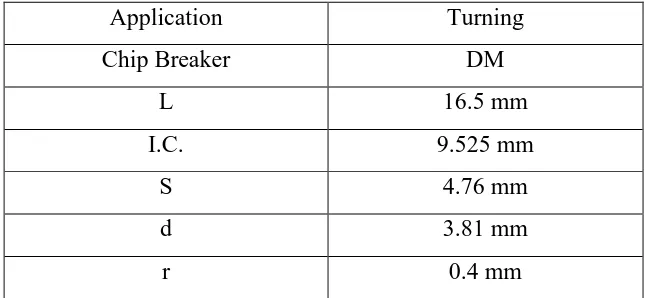
The cutting tool that will used in this machining is carbide insert with code number is TNMG160404- DM that shown in Figure 3.3 and Table 3.2 shows information about carbide.
Figure 3.3: Carbide Insert
Table 3.2: The information about carbide inserts (Source: Carbide Depot, 2015)
Name Description
ISO Code TNMG160404-DM
Material Tungsten Carbide
Angle 600
45
Application Turning
Chip Breaker DM
L 16.5 mm
I.C. 9.525 mm
S 4.76 mm
d 3.81 mm
r 0.4 mm
3.4 Process Parameter
[image:48.595.157.480.70.219.2]During the experiment, various cutting speeds and feed rate were tested when machining AISI 1045, meanwhile other parameters are keep constant. In this experiment, four cutting speeds and two feed rate have been selected in order to investigate the surface characteristics based on cutting speed variable. Table 3.3 shows all cutting parameters that will be applied in the experiment include cutting speeds and feed rates.
Table 3.3: Experiment Parameters
Cutting Speed (m/min)
Feed rate (mm/rev)
Depth of Cut (mm)
Cutting Condition
35
0.15
1.0
Dry Wet
41 Dry Wet
47 Dry Wet
53 Dry Wet
35
0.5
Dry Wet
41 Dry Wet
47 Dry Wet
46
3.5 Machining and Equipment
For the machine and equipment used in this experiment are:
(a) CNC Lathe Machine (b) EDM Wire Cut
(c) Surface Roughness Tester (d) Stereo Microscopes
(e) Scanning Electron Microscopes.
3.5.1 CNC Lathe Machine
[image:49.595.150.489.412.666.2]This experiment was conducted by CNC lathe machine model DMG MORI SEIKI, CTX 310 ecoline. The CNC lathe machine that was used in this experiment was shown in Figure 3.4 below and Table 3.4 shows the CNC lathe machine specification.
47
Table 3.4: CNC Lathe Machine Specification
Specification
Machine Serial Number 310
Model Number CTX
Brand Name SLIMline panel 15´´
Machine Made DMG Mori
Max Turning Diameter ø200 mm
Drive Power 16.5 kW
Machine Weight 3800 kg
Machine Speed 5000 RPM
Application Turning, facing, putting, knurling, screw thread run out, boring, screw thread undercut, radius or curvature and drilling.
3.5.2 Steps in Turning Operation
a) Marking process on the workpiece
First of all, the AISI 1045 was undergone centre drilling process at the edge of both sides. The centre drilling process is done by using conventional turning machine. The purpose of centre drilling process is to make sure correct alignment of the cylindrical AISI 1045 in the machine being placed centrally during CNC machining process. The process of centre drilling can be shown as in Figure 3.5.
48
Figure 0.5: Centre drilling process
b) Clamp the workpiece
[image:51.595.183.454.535.737.2]The workpiece then clamped using 3 jaw chuck. During material setting, balance between length and support from the tailstock is very important to avoid vibration during machining. Both dry and wet cutting was set according to the similar cutting length, for all cutting parameters that will be investigated. Figure 3.6 shows the position of AISI 1045 carbon steel setting on CNC turning machine
49 (c) Turning operation
[image:52.595.183.458.256.470.2]After that, a simple CNC program was generated to run the CNC turning machine at various machining parameters. Dry cutting process was carried out as no lubricant and cutting fluid present during wet machining condition. Every 5 mm cutting length was considered as one pass. The CNC turning machine that was being used for this project was DMG Mori Seiki CTX 310 ecoline. Figure 3.7 shows the CNC turning process.
50
3.6 Sample Preparation - EDM Wire Cut
[image:53.595.174.464.212.418.2]The workpiece has been cut into eight specimens with each dimensional 1mm × 1mm × 1mm by using Wire Cut Electrical Discharge Machining (EDM) shows in Figure 3.8. The purpose of this machining process is to obtain the desired size of specimens in order to simplify the further tasks for doing the analysis.
Figure 3.8: Wire Cut Electrical Discharge Machining (EDM)
3.7 Data Analysis
The equipment used in analysis of the surface integrity are:
(a) Surface Roughness Tester (b) Stereo Microscopes
51 3.7.1 Surface Roughness Tester
Surface roughness test is a profiling technique that will begin with the stylus measurement. It is a contact type roughness instrument as it will directly contact to the surface of the AISI 1045 carbon steel. In this study, the surface roughness test instrument that has been used was Mitutoyo Surftest SJ-410. Figure 3.9 shows the surface roughness tester of Mitutoyo Surftest SJ-401 while Table 3.5 shows its general information.
Figure 0.9: Surface roughness tester of Mitutoyo Surftest SJ-401.
Table 0.5: General specifications of surface roughness tester
No General Information
1 Serial number 178-956-3 D
2 Measuring method Skid-free/ with skid (switchable)
3 Measuring range: Z-Axis
X-Axis
800 mm, 80 mm, 8 mm 25 mm
4 User-defined Display/roughness parameter selectable
52 The workpiece was placed on the flat surface and must be secured from any movement during testing. The contacting stylus of the surface roughness test instrument is placed directly over the centre of the test sample. Then, the tip of the stylus will directly touch the surface of the sample. The stylus traced across each marked area for each experiment about 3 mm. The uses of stylus at the contact surface of workpiece is shows in Figure 3.10.
53 3.7.2 Stereo Microscope
Stereo microscope are used to observed the surface profile of AISI 1045 after machining under wet and dry condition with different cutting speed under low magnification (1.5 x magnificent).Figure 3.11 shows stereo microscopes and Table 3.6 shows general information of stereo microscopes.
[image:56.595.185.453.209.452.2]Figure 3.11: Meiji Stereo Microscopes type EMZ
Table 3.6: General Information for Stereo Microscopes
Machine Specification
Manufacture Meiji techno
Model No EMZ-13TR
54 3.7.3 Scanning Electron Microscope
[image:57.595.136.503.302.582.2]For surface profile characteristic electron scanning microscopes was used. This instrument able to capture images on cutting tool that cannot see with naked eyes. It also has a magnification range from 15x to 200,000x and a resolution of 5 nanometers. The Scanning Electron Microscope creates the magnified images by using electrons instead of light waves. A clear view of the micro image can be viewed by magnifying the image. Then capture the image before it is saved to the computer. Figure 3.12 shows scanning electron microscopes and Table 3.7 shows general information about SEM.
55
Table 3.7: General Information of SEM
Machine Specification
Manufacture and id no Carl Zeiss / 201737-H Model No Carl Zeiss AG - EVO® 50 Series Resolution 3.0nm @ 30kV (SE and W) 2.0nm @
56
CHAPTER 4
RESULTS AND DISCUSSION
This chapter presented results and discussion. Each result will be followed by respective analysis and discussion. Discussion is made in one section which is surface roughness and surface profile. The flow and steps of the analysis are explained throughout this chapter. Factors influencing each response are analysed accordingly.
4.1 Surface roughness
57
4.2 Surface roughness data and graph analysis
A statistical analysis was used to determine surface roughness of AISI 1045. Table 4.1 until Table 4.4 show information data for 0.15 mm/rev and 0.50 mm/rev feed rate at dry and wet cutting condition respectively. Surface roughness of every sample was taken using surface roughness tester based on average values. Figure 4.1 until Figure 4.4 show the trend in the surface roughness with varying machining speed when machining of AISI 1045 under dry and wet conditions
4.2.1 Wet Cutting Condition
Table 4.1: Wet cutting with various cutting speed for feed rate 0.15 mm/rev.
Wet
Cutting Speed (m/min)
Feed Rate (mm/rev)
Depth of Cut (mm)
Surface Roughness, Ra
(µm)
35 0.15 1 3.09
41 0.15 1 3.12
47 0.15 1 3.95
58
Figure 4.1: Surface Roughness,Ra (µm) Versus Speed (m/min) for wet cutting condition with feed
rate 0.15mm/rev
Figure 4.1 shows the line graph of the surface roughness, Ra versus cutting speed at wet condition at different spindle speed with constant feed rate 0.15 mm/rev. At the cutting speed 35 m/min, the value of surface roughness is 3.09 µm then increase until 3.12 at 41 m/min and keep increased gradually to 3.95 µm at 47 m/min. The line graph show that the surface roughness, Ra increase steadily between cutting speed 35 m/min to 47 m/min but there was slightly decrease at cutting speed 53 m/min. According to Chikalthankar et al.,(2014), the surface roughness will increased with an increasing in feed rate and depth of cut but decreased in cutting speed. AISI 1045 carbon steel shows surface roughness decreased started from 47 m/min to 53 m/min of cutting speed.
At cutting speed 35 m/min to 41 m/min which is low cutting speed, the sliding action between cutting tool and workpiece still in perfect condition this is due to the friction and temperature still lower. The cutting tool retain at it shape especially at the nose radius. During cutting process, fine condition will give fine surface roughness. When the cutting speed increase, cutting tool wear and nose radius not in the uniform shape. This condition will slide workpiece at imperfect condition where damage cut will slide the workpiece unbalance cutting force. Tool wear more obvious, temperature increase, friction also increase. On this situation, some phenomena occur, the workpiece
3.09 3.12 3.95 3.28 0 0.5 1 1.5 2 2.5 3 3.5 4 4.5
35 41 47 53
Su rf ace Rou gh n es s (µ m)
Cutting Speed (m/min)
59 material start to melt and material will flow side of feed mark. Therefore, this will affect the surface roughness get low value.
Table 4.2: Wet cutting with various cutting speed for feed rate 0.50mm/rev
Figure 4.2: Surface Roughness,Ra (µm) Versus Speed (m/min) for wet cutting condition with feedrate
0.5mm/rev Wet Cutting Speed (m/min) Feed Rate (mm/rev)
Depth of Cut (mm)
Surface Roughness, Ra
(µm)
35 0.50 1 16.33
41 0.50 1 15.77
47 0.50 1 15.02
53 0.50 1 18.07
16.33 15.77 15.02 18.07 0 2 4 6 8 10 12 14 16 18 20
35 41 47 53
Su rf ace Rou gh n es s (µ m )
Cutting Speed (m/min)
60 Figure 4.2 shows wet cutting condition at feed rate 0.50 mm/rev with different cutting speed. The line graph shows that the surface roughness, Ra slightly decreased followed cutting speed 35 m/min, 41 m/min, and slightly decrease at cutting speed 47 m/min. At higher cutting speed which is 53 m/min it shows the surface roughness increasing gradually. Thus, surface roughness decreased with the increased of cutting speed. From the graph above, the trending is much better compared to the graph surface roughness for wet cutting condition with feed rate 0.5mm/rev.
However, at higher cutting speed, it shows worse of surface roughness value. At low cutting speed which is 35 m/min, cutting tool retain it nose radius and it can slide very sharp well feed mark and in the end produce low surface roughness. The surface roughness become low as cutting speed increase at 41 m/min. When cutting speed is increase at 53 m/min, surface roughness starts to deteriorate, this is suspected to the high tool wear as the cutting speed increase. When tool wear increase, cutting speed also increase and this situation cannot produce good nose radius due to the workpiece force not stable.
[image:63.595.112.513.509.642.2]4.2.2 Dry Cutting Condition
Table 4.3: Wet cutting with various cutting speed for feed rate 0.15 mm/rev.
Dry
Cutting Speed (m/min)
Feed Rate (mm/rev)
Depth of Cut (mm)
Surface Roughness, Ra (µm)
35 0.15 1 3.80
41 0.15 1 3.85
47 0.15 1 5.86
61
Figure 4.3: Surface Roughness,Ra (µm) Versus Speed (m/min) for dry cutting condition with feedrate
0.15mm/rev
From Figure 4.3, the value of surface roughness was 3.80 μm when cutting speed at 35 m/min. When cutting speed increase at 41 m/min, the value of surface roughness slightly increased to 3.85μm and then increase gradually to 5.86μm when the cutting speed was 47 m/min. It was found that the value of surface roughness of AISI 1045 was increased from 3.80 μm to 5.86 μm (35.11%) between cutting speed 35 m/min to
47 m/min. Then, the surface roughness value suddenly decreased from 5.86 μm to 4.06 μm (30.68%) between cutting speed 47 mm/min to 53 mm/min.
It shows at lower cutting speed, temperature low, nose radius is good and can cut naturally. However, when cutting speed increase to maximum 53 m/min, is expected increase in cutting speed, will produce high friction, high temperature, cutting tool should wear, nose radius will not uniform anymore, slide in workpiece is unbalance. This condition contributes to increase the surfave roughness value.
3.8 3.85 5.86 4.06 0 1 2 3 4 5 6 7
35 41 47 53
Su rf ace Rou gh n es s (µ m )
Cutting Speed (m/min)
62
[image:65.595.112.546.220.511.2]Table 4.4: Dry cutting with various cutting speed for feed rate 0.50mm/rev
Figure 4.4: Surface Roughness,Ra (µm) Versus Speed (m/min) for dry cutting condition with feedrate
0.5mm/rev
From Figure 4.4, the value of surface roughness was 8.68 μm at cutting speed 35 m/min. As the cutting speed increase to 41 m/min, the surface roughness was slightly increase to 8.86 μm. It shows the surface roughness keep increasing at cutting speed 47 m/min and also at 53 m/min which 11.39 μm and 17.28 μm respectively. The lowest value of surface roughness was obtained at spindle speed 35 m/min while the highest value of surface roughness was obtained at spindle speed 53 m/min. From the line graph, the value of surface roughness for AISI 1045 was increased as the spindle speed value of dry turning increased at feed rate 0.50 mm/rev. In dry turning operation of
8.68 8.86 11.39 17.28 0 2 4 6 8 10 12 14 16 18 20
35 41 47 53
Su rf ace Rou gh n es s (µ m )
Cutting Speed (m/min)
Surface Roughness (Ra) vs Speed
DryCutting Speed (m/min)
Feed Rate (mm/rev)
Depth of Cut (mm)
Surface Roughness, Ra (µm)
35 0.50 1 8.68
41 0.50 1 8.86
47 0.50 1 11.39
63 AISI 1045, the surface roughness increased as the feed rate increased. Selvaraj and Chandramohan (2010) in their study stated that this situation is due to the widening in the area of contact and changes in the force per unit length, resulting in great distortion of sticky chip. Hence, it can be said that the lowest value of surface roughness was achieved at low feed rate which was 0.15 mm/rev as compared to the values at high feed rate.
[image:66.595.112.310.299.411.2]4.2.3 Comparison dry and wet cutting condition
Table 4.5: Data of surface roughness, Ra at dry and wet (Feed Rate 0.15mm/rev)
Wet (Ra) Speed
(rpm)
Surface roughness (µm)
275 3.09
325 3.12
375 3.95
425 3.28
Dry (Ra) Speed
(rpm)
Surface roughness (µm)
275 3.80
325 3.85
375 5.86
64
Figure 4.5: Graph comparison of surface roughness,Ra vs speed (FeedRate 0.15mm/rev)
Figure 4.5 shows graph of comparison between wet and dry cutting condition at feed rate 0.15mm/rev. The wet cutting conditions shows the lower surface roughness compare to dry cutting condition. At lower feed rate, wet cutting condition is better than dry cutting condition. This phenomenon occurs due to cutting contribute lubrication and cooling effect. It can retain nose radius and the coolant slide into the workpiece very well.
Table 4.6: Data of surface roughness Ra at dry and wet (Feed Rate 0.50mm/rev)
3.09 3.12 3.95 3.28 3.8 3.85 5.86 4.06 0 1 2 3 4 5 6 7
275 325 375 425
Su rf ace Rou gh n es s, Ra (µ m ) Speed (rpm)
Comparison between Wet and Dry condition of Ra
(FeedRate 0.15mm/rev)
Wet Dry Wet (Ra) Speed (rpm) Surface roughness (µm)275 16.33
325 15.77
375 15.02
425 18.07
Dry (Ra) Speed
(rpm)
Surface roughness (µm)
275 8.68
325 8.86
375 11.39
65
Figure 4.6: Graph comparison of surface roughness, Ra vs speed (Feed Rate 0.50mm/rev)
Figure 4.6 shows both results of surface roughness in wet and dry condition at feed rate 0.50mm/rev. From the graph it shows that as the feed rate increase, dry cutting better than wet cutting, this situation occurs because of at the higher feed rate, the force moves fast and give high pressure between cutting tool and workpiece will restrict the penetration of the cooling. Therefore, on this time, the coolant provides small cooling action and shift the chips away from the cutting region. This phenomenon demonstrate that cutting fluid did not show a significant effect to the surface finish. The use of cutting fluid just benefitted the machining performance in terms of chip removal in order to avoid them entangled with the cutting tool. This results is consistent with Yahya, 2010, where he found that the cutting fluid did not give a big impact on surface roughness during the machining trial on effect of cutting fluids in turning AISI 1045 steel with coated carbides tool.
16.33 15.77 15.02 18.07 8.68 8.86 11.39 17.28 0 2 4 6 8 10 12 14 16 18 20
275 325 375 425
Su rf ace Rou gh n es s, Ra (µ m ) Speed (rpm)
Comparison between Wet and Dry condition of Ra
(FeedRate 0.50mm/rev)
66
4.3 Surface Profile
[image:69.595.112.561.125.612.2]
Table 4.7: Surface Profile for feed rate 0.15 mm/rev at Dry and Wet condition.
FEED RATE 0.15 mm/rev
CUTTING
SPEED DRY WET
35
41
47
Feed mark
Feed mark
Feed mark
Feed mark
67 Table 4.7 until Table 4.8 shows the micrograph of surface under wet and dry cutting with various cutting speed by using Scanning Electron Microscope. From the results, the surfaces produced are still considered to be well-defined of the feed mark that occur in the form of peak and valley profile. At dry cutting, it shows that fine feed mark occur. For example, at cutting speed 34 m/min and 41 m/min. In general, it can see at low cutting speed, fine surface profile demonstrated on machining surface, it can observed fine feed mark peak and valley which reflected smooth and shiny surface after machining. As the cutting speed increase some of the image shown obviously differentiation between peak and valley where the image of peak seems higher as compare to the lower cutting speed. This could be due to tool wear that come from the uneven action from the ununiformed nose radius.
There are also evidence of material slide flow for smearing surface due to the molten workpiece material resulting from high cutting temperature. This evidence can see at cutting speed 53 m/min at dry condition. Even surface roughness demonstrate lower surface roughness value, but surface profile demonstrate deteriorate surface condition which is showing that the surface is not in fine condition. Therefore, the use of cutting parameter in this condition is not recommended.
In wet cutting condition, it shows the surface profile are fine feed mark and shows smooth surface finishing due to the cooling action from coolant. The surfaces generated under the conditions investigated were well-defined and free from other damage such as cracking, tearing and rupture that are detrimental to machined components.
53
68
Table 4.8: Surface Profile for feed rate 0.50 mm/rev at Dry and Wet condition.
FEED RATE 0.5 mm/rev CUTTING
SPEED DRY WET
35
41
47
53
Feed mark Feed mark
Feed mark Feed mark
Feed mark Feed mark
Feed mark Feed mark
Material side flow Material side flow
Material side flow
69 Figure 4.8 shows the results of surface profile at dry and wet condition at feed rate 0.5 mm/rev. At dry cutting condition, the feed mark shows very fine and smooth at the cutting speed 35 m/min and 41 m/min. But as the cutting speed increase at 47 m/min, there are evidence of surface deteriorate at the half side of the feed mark. This phenomenon occur probably due to worn region at the edge of the cutting tool.
Overall at low feed rate of 0.15 mm/rev, the surface roughness increase as the cutting speed increase. Whereas at high feed rate 0.50 mm/rev, the surface roughness demonstrate constant surface roughness value as the cutting speed increase. This indicate there are evidence of crater wear. Crater wear usually occur due to the heat at rake face diffusion of work materials. This material side flow that occur at cutting speed 47 m/min, will give effect to the strength of the workpiece in fatigue condition, it will ease for the crack may happened. This situation consistently occurred at higher cutting speed which is 53 m/min.
70
CHAPTER 5
CONCLUSION
5.1 Conclusion
This project presents the experimental evaluation on machinability of AISI 1045 under dry and wet condition. From the machining data obtained, the conclusions can be drawn. At lower feed rate at 0.15 mm/rev, wet cutting produce better surface roughness compare to dry cutting. Minimum surface roughness is 0.39 μm for wet whereas minimum surface roughness for dry is 3.8 μm. However, at high feed rate at 0.5 mm/rev, the surface finish for dry is better than wet. Minimum surface roughness for dry is 8.6 μm whereas minimum surface roughness for wet is 15.02 μm. The effect of cutting fluid can be negligible at high feed rate at 0.5
In terms of the surface profile, its shows for both dry and wet appear to be feed mark according to the nose radius. However, the feed rate for 0.5 mm/rev is wider due to the higher value. There are evidence of material side flow, metal detachment and deteriorate surface finish at some area at the surface. There are also the evidence of side worn along feed mark due to the worn surface of cutting tool.
71
5.2 Recommendation for Future Work
There are few recommendations provide as to extend understanding of fundamental in surface roughness, as well as to improve the machining process in order to gain a better surface finish and gain more information about surface roughness with the different conditions use while machining are;
a) The experimental work in this project has focused only for material Carbon Steel AISI 1045. It is recommended that further research be conducted for a variety of material such as Aluminium and Mild Steel.
b) The result shows the cutting fluid did not give a big impact on the surface roughness, it may be interesting to conduct this research by using another coolant types and the volume of coolant may be change.
72
5.3 Sustainable Development
Sustainable manufacturing consists of environmental protection, profitability and societal benefit for all industrial areas. Manufacturing practices are investigated for optimize production efficiency while minimizing environmental impact and maintaining social equity (Jayal et al., 2010). It can be achieved through changes in products, processes and systems related to the sustainability issues. To improve the sustainability of machining processes researchers are making efforts to eliminate or reduce the use of cutting fluids during machining through several means: development of improved tool coatings, materials and cutting fluids, hybrid machining processes and process optimization.
There are two main stages for sustainable development in this research:
a) Scrap steel and chips b) Coolant usage
5.3.1 Scrap steel and chips
Steel’s durability allows for the reuse of countless products, which is enhanced through
73 5.3.2 Coolant usage
74
REFERENCES
Atul Kumar, Dr. Sudhir Kumar, Dr. Rohit Gard, 2011. Statistical modelling of surface roughness in turning process.Engineering Science and Technology, 3 (5) (2011), pp. 4246-4252.
A.G.F. Alabi, T.K. Ajiboye and H.D. Olesegun, 2010.Investigating the cutting force in heat treated medium carbon steel when turning on a lathe machine.Engineering Design and Technology, 8 (1) (2010), pp. 80-93.
Basim A. Khidhir, Bashir Mohamed, 2010.Study of cutting speed on surface roughness and chip formation when machining nickel-based alloy. Mechanical Science and Technology, 24 (5) (2010), pp. 1053-1059.
Chou, Y. and Evans, C. J. Microstructural Effects in Precision Hard Turning, ASME Manufacturing Engineering Division, 4 (1996) pp.237-242.
G. List , M. Nouari , D. G´ehin , S. Gomez, J.P. Manaud, Y. Le Petitcorps , F. Girot. Wear behaviour of cemented carbide tools in dry machining of aluminium alloy, Wear 255 (2003) pp.1359–1368.
G.S. Hanumanth, G.A. Irons, Particle incorporation by melt stirring for the production of metal-matrix composites, J. Mater. Sci. 28 (1993) 2459–2465.
Harisingh, PradeeppKumar,Tool wear optimization in turning operation by Taguchi Method, Indian journal of engineering and material science, 11 (2004) pp. 19-24.
H aouici1,2, MA yallese, a Belbah,Mfameur and M Elbah , 2013. Experimental
investigation of cutting parameters influence on surface roughness and cutting forces
75 Hyun WookLee, Won Tae Kwon, 2010. Determination of the minute range for RSM to select the optimum cutting condition during turning on CNC Lathe.Mechanical Science and Technology. 24 (8) (2010), pp. 1637-1645.
J. Paulo Davim. (2010). Surface Integrity in Machining. Springer
Kalpakjian, S., and Schmid, S.R., 2013.Manufacturing Engineering and Technology, 7th ed., New Jersey: Prentice-Hall.
Kim,W.,andKwon,P. Phase Transformation and its effect on flank wear in machining steel.Journal of Materials and Manufacturing Engineering 124 (2002), pp.659-666.
Kumar, D., & Kumar, A. (2014). Improving Surface Finish and Hardness for M . S . Cylinder using Roller Burnishing, 3(1), 47–51.
Larry Horath. (2011). Fundamentals of Materials Science for Technologists. (L. Horath, Ed.) (fourth edi). Prentice Hall.
MeenuShahu, KomeshShahu, Optimization of cutting parameters on tool wear, workpiece surface temperature and material removal rate in turning of AISI D2 steel, Advanced Mechanical Engineering, 4 (2014), pp. 291-298
Mohan Singh, DharmpalDeepak and Manoj Singla, 2010, A Comprehensive
Study Of OperationalCondition For TurningProcess To Optimize. The Surface
RoughnessOf Object, International JournalonEmergingTechnologies. 1(1), p.p.
97-101.
Prasad, K. (2013). Influence of Cutting Parameters on Turning Process Using Anova
Analysis, 2(9), 1–6.
76 S. Thamizhmanii, S. Saparudin, S. Hasan, 2007. Analyses of surface roughness by turning process using Taguchi Method.Materials and Manufacturing Engineering, 20 (1-2) (2007), pp. 503-506.
77 Figure of Surface Profile under Stereo Microscope using 1.5x magnifivcation
FEED RATE 0.15 mm/rev CUTTIN
G SPEED
DRY WET
275
325
375
78 FEED RATE 0.5 mm/rev
CUTTIN G SPEED
DRY WET
275
325
375