Strength modelling of Al Cu Mg Type alloys
229
0
0
Full text
(2) UNIVERSITY OF SOUTHAMPTON FACULTY OF ENGINEERING, SCIENCE & MATHEMATICS School of Engineering Sciences Materials Research Group. Strength Modelling of Al-Cu-Mg Type Alloys By. Jialin Yan. Thesis for the degree of Doctor of Philosophy. March 2006.
(3) UNIVERSITY OF SOUTHAMPTON ABSTRACT FACULTY OF ENGINEERING, SCIENCE AND MATHEMATICS SCHOOL OF ENGINEERING SCIENCES MATERIALS RESEARCH GROUP Doctor of Philosophy STRENGTH MODELLING OF Al-Cu-Mg TYPE ALLOYS By Jialin Yan Age hardening of Al-Cu-Mg type alloys occurs in two stages separated by a constant hardness plateau when the alloys are aged at 110°C to 240°C after solution treatment and quenching. This work aims to develop a physically based two-stage hardening model to predict the yield strength of Al-Cu-Mg alloys with compositions in the (α+S) phase region. Experiments by means of hardness and tensile tests, differential scanning calorimetry and transmission electron microscopy (TEM) have been carried out to provide the relevant information for the calibration and validation of the model. The model considers a simplified precipitation sequence which involves a preprecipitate structure followed by S phase. This pre-precipitate structure is referred to as Cu-Mg co-clusters instead of GPB zones based on atom probe and TEM studies from collaborators and a review of the literature. The competition between the Cu-Mg coclusters and the S phase is modelled by assuming S phase forms at the expense of CuMg co-clusters. In the model, the solvi of the Cu-Mg co-clusters and the S phase are calculated, the evolution of precipitates in terms of volume fraction, average size and the solute concentration in the matrix are described and the superposition of various contributions from precipitation strengthening, solution strengthening and dislocation strengthening are modelled. Strengthening by Cu-Mg co-clusters and S phase is described by the modulus strengthening mechanism and the Orowan bypassing mechanism, respectively. The predicted contributions to the critical resolved shear stress show that strengthening in the alloys is mainly due to the Cu-Mg co-clusters in the first stage of hardening and due to the S phase in the second stage of hardening. The model takes account of the composition dependency of precipitation rate for Cu-Mg coclusters formation as well as the amount of Cu and Mg present in undissolved intermetallic phases. With a training root mean square error of 12MPa on an artificially aged 2024 alloy, the modelling accuracy on unseen yield strength data of two other alloys is 16MPa. Using a single set of parameters, the model has been applied to predict the hardness of a 2024-T351 alloy artificially aged at low temperature followed by short term underageing at higher temperature and then room temperature ageing. Good agreement between the predictions and the experiments indicates that the hardness changes during these multi-stage heat treatments can be well interpreted by considering Cu-Mg cocluster dissolution, S precipitation and Cu-Mg co-cluster re-formation. Application to Al-xCu-1.7Mg alloys (x=0.2, 0.5, 0.8 and 1.1at.%) has shown good predictive capabilities of the model for the first stage of hardening. It is also shown that the model is applicable to Al-Cu-Mg alloys with Si contents at levels of 0.1-0.2wt.%. Modelling results of various Al-Cu-Mg alloys during natural ageing, artificial ageing and multistage heat treatments indicate that the model is capable of predicting the evolution of microstructure and the yield strength as a function of composition and heat treatments, and can provide a predictive tool for predicting the strength of Al-Cu-Mg based welds..
(4) CONTENTS Contents. i. Preface. v. Acknowledgements. vi. Nomenclature. vii. List of Abbreviations. xi. Chapter 1 Introduction...........................................................1 Chapter 2 Literature Review .................................................4 2.1. Introduction to aluminium alloys..................................................5. 2.1.1. Aluminium alloy and temper designations ......................................5. 2.1.2. General metallurgical features .........................................................6. 2.1.3. Basics of precipitation hardening.....................................................7. 2.2. Precipitation in Al-Cu-Mg based alloys .......................................8. 2.2.1. Phase diagram ..................................................................................8. 2.2.2. Microstructural development .........................................................10. 2.2.2.1. Al-Cu based alloys .........................................................................10. 2.2.2.2. Al-Cu-Mg based alloys ..................................................................10. 2.2.3. Age hardening in Al-Cu-Mg based alloys .....................................17. 2.2.3.1. Al-Cu based alloys .........................................................................17. 2.2.3.2. Al-Cu-Mg based alloys ..................................................................18. 2.2.4. 2.3. Effect of Si on age hardening of Al-Cu-Mg alloys........................21. Modelling of microstructure evolution.......................................24. 2.3.1. Modelling of precipitation thermodynamics..................................25. 2.3.2. Modelling of precipitation kinetics................................................27. i.
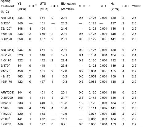
(5) 2.3.2.1. Classical models for the nucleation regime, growth regime and coarsening regime..........................................................................28. 2.3.2.2. Models with numerical solutions for nucleation, growth and coarsening......................................................................................31. 2.3.2.3. Models with analytical solutions for nucleation and growth.........32. 2.3.2.4. Starink-Zahra model [107, 136] ....................................................35. 2.4. Modelling of yield strength ........................................................38. 2.4.1. Major mechanisms of strengthening..............................................38. 2.4.2. Models for the critical resolved shear stress and yield strength ....39. 2.4.3. Superposition of strengthening mechanisms .................................42. 2.5. Integrated models for yield strength ...........................................44. Chapter 3 Experimental .......................................................78 3.1. Materials .....................................................................................78. 3.2. Heat treatments ...........................................................................79. 3.2.1. Artificial ageing .............................................................................79. 3.2.2. Natural ageing................................................................................80. 3.2.3. Multi-stage ageing .........................................................................81. 3.3. Vickers hardness tests.................................................................81. 3.4. Tensile tests.................................................................................81. 3.5. Differential scanning calorimetry and isothermal calorimetry...82. 3.6. Transmission electron microscopy and image analysis..............84. Chapter 4 Results and Analysis ...........................................92 4.1. Mechanical properties.................................................................92. 4.1.1. Artificial ageing .............................................................................92. 4.1.2. Natural ageing................................................................................93. 4.1.3. Multi-stage ageing .........................................................................94. 4.2. Conversion of Vickers hardness to yield strength ......................95. 4.2.1. Background ....................................................................................95. 4.2.2. New method for conversion of Vickers hardness to yield strength ... ........................................................................................................96 ii.
(6) 4.2.3. 4.3. Analysis of the method ..................................................................97. Calorimetric studies ....................................................................98. 4.3.1. Isothermal calorimetry ...................................................................98. 4.3.2. DSC................................................................................................99. 4.3.3. Determination of kinetic parameters............................................102. 4.3.3.1. Determination of the activation energy .......................................102. 4.3.3.2. Determination of the transformation exponent for cluster formation ......................................................................................................105. 4.4. TEM and image analysis...........................................................107. Chapter 5 The model...........................................................137 5.1. Introduction...............................................................................137. 5.2. Thermodynamic Model.............................................................138. 5.2.1. Solvi of Cu-Mg co-clusters and S phase......................................138. 5.2.2. Undissolved intermetallic phases.................................................140. 5.3. Kinetic Model ...........................................................................142. 5.3.1. Evolution of volume fraction and mean solute concentration .....142. 5.3.2. Evolution of average precipitate size...........................................144. 5.3.3. Effect of solute content on homogeneous precipitation kinetics .146. 5.4. Strength Model .........................................................................148. 5.4.1. Cluster strengthening ...................................................................149. 5.4.2. S phase strengthening ..................................................................150. 5.4.3. Solid solution strengthening ........................................................152. 5.4.4. Dislocation strengthening ............................................................154. 5.4.5. Grain boundary strengthening......................................................155. 5.4.6. Overall strength............................................................................155. 5.5. Summary ...................................................................................156. Chapter 6 Model Assessment and Discussion...................168 6.1. Introduction...............................................................................168. 6.2. Modelling of natural age hardening..........................................168. 6.2.1. The kinetics of cluster formation .................................................169. iii.
(7) 6.2.2. 6.3. Modelling of yield strength development ....................................171. Modelling of artificial age hardening .......................................173. 6.3.1. Calibration of the model ..............................................................174. 6.3.2. Parametric study...........................................................................176. 6.3.3. Validation of the model ...............................................................178. 6.3.3.1. Evolution of the yield strength .....................................................178. 6.3.3.2. Evolution of the volume fraction of S precipitates and the rate of S precipitation.................................................................................179. 6.3.3.3 6.3.4. Evolution of the radius of S precipitates......................................180 Applications of the model............................................................181. 6.3.4.1. Modelling of the hardness during multi-stage heat treatment.....181. 6.3.4.2. Modelling of the early stages of age hardening...........................183. 6.3.4.3. Modelling of age hardening of alloys with small additions of silicon...........................................................................................185. 6.4. Discussion .................................................................................187. 6.4.1. Coarsening kinetics of S precipitates...........................................187. 6.4.2. Mechanisms for cluster strengthening .........................................188. 6.5. Limitations of the model and suggestions for further work .....190. 6.6. Summary ...................................................................................191. Chapter 7 Summary and Conclusions...............................212. iv.
(8) PREFACE This thesis is submitted for the degree of Doctor of Philosophy at the University of Southampton. The research work described herein was carried out wholly by the author under the supervision of Professor M.J. Starink in the Materials Research Group, School of Engineering Sciences, University of Southampton, during the period of October 2001 to January 2006.. This work is to the best of my knowledge original and this thesis is entirely my own work, except where acknowledgements and reference are made to other published work or work done by collaborators. No part of this thesis has been submitted for any other degree at any other university. This thesis does not exceed 75,000 words.. Parts of this work have been presented in the following publications: [1]. M. J. Starink, A. Cerezo, J. Yan, and N. Gao, 'Reply to the Comments on “Roomtemperature precipitation in quenched Al-Cu-Mg alloys: a model for the reaction kinetics and yield-strength development.”', accepted for Philos. Mag. Lett., 2006.. [2]. M. J. Starink and J. L. Yan, 'Precipitation hardening in Al-Cu-Mg alloys: analysis of precipitates, modelling of kinetics, strength predictions', accepted for Proc. 10th International Conference on Aluminium Alloys (ICAA10), 2006.. [3]. M. J. Starink, N. Gao, L. Davin, J. Yan and A. Cerezo, 'Room temperature precipitation in quenched Al–Cu–Mg alloys: a model for the reaction kinetics and yield strength development', Philos. Mag., 2005, 85, 1395-1417. o I co-wrote the sections on kinetics and strength modelling with my supervisor.. [4]. J. Yan, M. J. Starink, and N. Gao, 'Modelling of Precipitation Hardening of Al-Cu-Mg Alloys', in: J.F.Nie, A.J.Morton, and B.C.Muddle (Eds.), Proc. 9th International Conference on Aluminium Alloys (ICAA9), Institute of Materials Engineering Australasia Ltd., Brisbane, Australia, 2-5 August, 2004, p.926-932.. [5]. M. J. Starink, N. Gao, and J. L. Yan, 'The origins of room temperature hardening of Al-CuMg alloys', Mater. Sci. Eng. A, 2004, 387-389, 222-226. o I contributed to the analysis of cluster hardening mechanisms.. [6]. M. J. Starink and J. Yan, 'A model for strengthening of Al-Cu-Mg alloys by S phase', in: M. Tiryakioglu and L. A. Lalli (Eds.), 1st International Symposium on Metallurgical Modeling for Aluminum Alloys, ASM Materials Solution 2003, Pittsburgh, PA, October 12-15, 2003, p.119-126. o Most of the text was written by my supervisor. I wrote the modelling programme, did the tensile tests and DSC experiments, analysed TEM data.. Jialin Yan January 2006. v.
(9) ACKNOWLEDGEMENTS I would like to express my sincere thanks to my supervisor Professor Marco J. Starink for his guidance, inspiration and patience. I am indebted to the School of Engineering Sciences, University of Southampton for financial support.. I would like to acknowledge and thank Dr. Philippa Reed for her support in my application for conference attendance fund, and to Dr. Ian Sinclair for his helpful suggestions and important comments on my work. My appreciation is also extended to Dr. Krishnamurthy Raviprasad of Nanotechnology Victoria, Australia and Dr. Nong Gao for the supply of unpublished experimental data, and to Dr. Shuncai Wang for his assistance with TEM.. I take this opportunity to thank all the members of the Materials Research Group for their kind help. In particular thanks go to Professors P.J. Gregson and A. Willoughby, Mr. D. Beckett, Mr. E. Bonner, Mr. E. Roszkowiak, Mrs. S. Walker, Mrs. G. Skiller, Dr. X.M. Li, Dr. J.Y Chen, Dr. N. Kamp, Dr. P. Rometsch, Dr. M. Joyce, Dr. L. Wang, Dr. Y.M. Xu, Dr. A.H. Wu, Dr. J. Liu, Dr. K.H. Khor, Dr. H.T. Pang, Dr. F. Lefebvre, Mr. M. Miller, Mr. J. Sun, Ms.Z.Z. Hua, Ms. L. Venning, Ms. P. Kittidachachan, Mr. I. Khan and Mr. M. Ali. Thanks also to my other friends in Southampton who have made my time here much easier and happier.. Finally I wish to express my gratitude to my family members for their understanding, encouragement and support. Special thanks to my husband and my son for everything.. vi.
(10) NOMENCLATURE a. lattice parameter of precipitate (m). Aa. a constant. Ae. total area of the exothermic/endothermic heat effect. b. magnitude of the Burgers vector (m). c1, c2. pre-exponential factors. c. solute concentration in the matrix (at%). cg. gross solute concentration in the matrix (at%). c0. initial solute concentration in the matrix (at%). ce. equilibrium solute concentration (at%). ceff. effective solute concentration in the matrix (at%). cr. solute concentration at the particle/matrix interface (at%). cp. equilibrium solute concentration of precipitate (at%). cclCu. atomic fraction of Cu in the Cu-Mg co-clusters (at%). c clMg. atomic fraction of Mg in the Cu-Mg co-clusters (at%). d. diameter of the cross-section of the particles (m). dGB. average grain size (m). D. diffusion coefficient of the solute in the matrix (m2/s). D0. pre-exponential factor. Dr. diameter of the rod-shaped precipitates (m). Ea. activation energy for reaction (J/mol). E a ,c. activation energy for coarsening (J/mol). Eeff. effective activation energy for nucleation and growth (J/mol). EG. activation energy for growth (J/mol). EN. activation energy for nucleation (J/mol). f. volume fraction of precipitates. Fm. obstacle strength (N). ΔFv. driving force per unit volume for precipitation (J/m3). G. growth rate (m/s). G0. pre-exponential factor (m/s). ΔGo. standard Gibbs free energy of reaction (J/mol) vii.
(11) ΔG*. activation energy barrier for nucleation of precipitates (J/mol). ΔH0. standard enthalpy of reaction (J/mol). ΔH. formation enthalpy (J/mol). I. nucleation rate (/m3s). I0. pre-exponential factor (/m3s). k. rate constant for precipitation (/s). kB. Boltzman constant. kc. rate constant for coarsening (nm3/s). k0. pre-exponential constant for precipitation (/s). k o ,c. pre-exponential constant for coarsening (nm3/s). kCu. strengthening coefficient of Cu atoms (MPa/at.%Cu). kMg. strengthening coefficient of Mg atoms (MPa/at.%Mg). kHP. Hall-Petch coefficient (MPa m ). kn. a constant. K. equilibrium constant. KA. strain hardening factor (MPa). L. effective obstacle spacing in the slip plane (m). l (t ). average precipitate size (m). l0. average size of precipitates at the start of coarsening (m). lc. average size of precipitates in the coarsening stage (m). lg. average size of precipitates in the nucleation and growth stages (m). lr. length of the rod-shaped precipitates. Ls. average planar spacing of particles in the slip plane. m. a constant. M. Taylor factor. n. reaction exponent or strain-hardening exponent. N. precipitate number density (/m3). N0. number of atoms per unit volume (/m3). q. superposition exponent. Qd. activation energy for diffusion of the solutes in the matrix (J/mol). ΔQ. heat evolved due to the formation or dissolution of the precipitates (J/g). ΔQAQ heat evolved of the cluster formation effect in as-quenched condition (J/g) viii.
(12) ΔQAR heat evolved of the S formation effect in as-received condition (J/g) ΔQt. heat evolved of the exothermic effect for sample aged for time t (J/g). ΔQTp heat evolved at peak temperature (J/g) ΔQ∞. heat evolved of the exothermic effect for sample aged for very long time (J/g). r. radius of spherical precipitates (m). re. effective particle radius (m). r0. dislocation inner cut-off radius (m). r. average radius of precipitates (m). ro. initial average radius of precipitates (m). r*. critical radius for nucleation (m). R. universal gas constant (8.314 J/Kmol). s. reaction exponent. ΔS0. standard entropy of reaction. t. ageing time (s). te. time when the heat flow is 0.5% of the maximum heat flow. tf. time needed for a fixed fraction transformed (s). tp. time to peak heat flow (s). teq. equivalent time (s). T. absolute temperature (K). Tav. average temperature of a temperature range (K). Tp. peak temperature (K). Ts. solvus temperature (K). Vat. atomic volume of precipitate (m3). Vm. molar volume of precipitates (m3/mol). Vt. actual transformed volume. Ve. extended volume. x. amounts (the number of moles) of precipitates (at%). z. time at which the nucleus is formed (s). Z. Zeldovich factor. α. fraction transformed. αext. extended fraction. β. heating rate (K/s) ix.
(13) β*. frequency factor or rate of impingement (/s). γ. particle/matrix interfacial energy (J/m2). Γ. dislocation line tension. Δμ. difference in shear modulus between matrix and Cu-Mg co-clusters (GPa). ΔσGB strengthening increment due to grain boundaries (MPa) Δσss. increment in yield strength due to solid solution strengthening (MPa). Δτ. critical resolved shear stress (CRSS) (MPa). Δτ cl. CRSS contribution from modulus strengthening (MPa). Δτ ch CRSS contribution from chemical hardening (MPa) Δτ d. CRSS contribution from discolation strengthening (MPa). Δτ S. CRSS contribution from S strengthening (MPa). Δτ Σ. CRSS contribution from discolation strengthening and S strengthening (MPa). Δτ ppt CRSS contribution from Δτ ∑ and cluster strengthening Δτcl (MPa). ε. true strain. ηi. impingement exponent. λi. impingement parameter. λ1, λ2 proportionality constants μCu. shear modulus of copper (48.3GPa). μMg. shear modulus of magnesium (17.3GPa). μAl. shear modulus of aluminium (26.2GPa). μcl. shear modulus of Cu-Mg co-clusters (GPa). ν. Poisson’s ratio for Al. vN. average volume of a single nucleus (m3). ρN. number density of growing nuclei (/m3). σ. true stress. σi. intrinsic strength of Al matrix (MPa). σy. conventional yield strength (MPa). ψc. breaking angle for a gliding dislocation to overcome the obstacles. x.
(14) LIST OF ABBREVIATIONS 1DAP. one dimensional atom probe. 3DAP. three dimensional atom probe. APFIM. atom probe field ion microscopy. BF. bright field. CDB. Coincidence Doppler Broadening. CRSS. critical resolved shear stress. DIC. differential isothermal calorimetry. DSC. differential scanning calorimetry. EBSD. electron backscatter diffraction. EDS. energy dispersive spectroscopy. GP zones. Guinier-Preston zones. GPB zones. Guinier-Preston-Bagaratsky zones. HF. heat flow. HREM. high resolution electron microscopy. Hv. Vickers hardness. ODF. orientation distribution function. RMSE. root mean square error. SAD. selected area diffraction. SAXS. small angle X-ray scattering. SEM. scanning electron microscopy. STD. standard deviation. TEM. transmission electron microscopy. UTS. ultimate tensile strength. XRD. X-ray diffraction. YS. yield strength. xi.
(15) Chapter 1 Introduction. Chapter 1. Introduction. 2xxx series Al-Cu-Mg aluminium alloys are precipitation hardenable alloys that rely on the precipitation of fine (metastable) precipitates for strengthening. Among the 2xxx alloys, the 2024-T3 alloy (which is solution treated, cold worked and naturally aged) is widely used in the civil aerospace industry due to its good combination of specific strength and damage tolerance. Traditionally the requirements for high specific strength, high fracture toughness and good fatigue crack growth resistance are mostly fulfilled via the appropriate alloy chemistry and thermo-mechanical treatment by trial and error based on metallurgical experience. This can be costly and slow. Therefore as a cost effective approach to improve the properties of existing materials and to develop new materials, development of models to relate the process parameters (alloy composition, heat treatment temperature and time) to the mechanical properties such as yield strength via microstructure evolution is highly desirable. Over the last fifteen years, the increasing demand for materials optimization has led to the development of physically based models with varying approaches and complexity for microstructure evolution and precipitation hardening in 2xxx series [1-4], 6xxx series [5, 6], 7xxx series [7-10] and 8xxx series [11] aluminium alloys. The published age hardening models for Al-Cu alloys developed by Shercliff and Ashby [1] and by Liu et al. [2] both consider a single precipitate throughout the ageing process; thus these models are applicable only for the ageing curves with a single peak. Models for AlCu-Mg alloys developed by Gomiero et al. [3] and by Genevois et al. [4] consider various precipitates, but using measured microstructural parameters for the prediction of the yield strength. It would thus be beneficial to be able to predict the evolution of microstructural parameters based on alloy composition and thermal history.. 1.
(16) Chapter 1 Introduction Age hardening of Al-Cu-Mg type alloys with composition in the (α+S) phase field occurs in two distinct stages separated by a constant hardness plateau when the alloys are aged at 110°C to 240°C after solution treatment and quenching [12]. The aim of this work is to develop a physically based two-stage age hardening model to predict the yield strength of Al-Cu-Mg type alloys as a function of composition and heat treatments. The model would consider two types of precipitates; describe the thermodynamics and kinetics of microstructure evolution and the yield strength evolution. The model will be designed such that it can describe precipitation kinetics and precipitation hardening by an analytical method, with a minimum of computational effort while showing good accuracy of predictive power.. This work involves extensive analysis of theory and models, with experimental work especially aimed at providing key information that is directly relevant to evaluate the validity of the model. Experimental data for the calibration and validation of the model are from three sources: from experiments performed for this work on four AlCu-Mg alloys as presented in this thesis, from experiments performed for other projects at the University of Southampton and from the literature. In this work, the mechanical properties have been investigated by Vickers hardness and tensile tests. The precipitation kinetics has been studied using differential scanning calorimetry (DSC) and isothermal calorimetry. Microstructure characterization has been carried out using transmission electron microscopy (TEM).. The structure of this thesis is as follows: firstly a literature review in Chapter 2 covers published experimental studies of the age hardening behaviour in Al-Cu-Mg based alloys, the approaches of modelling of microstructure evolution and of the yield strength, and the existing strengthening models for aluminium alloys. Chapter 3 describes the experimental techniques used in the present study. Then the results and analysis of the kinetic study, mechanical tests and TEM analysis are presented in Chapter 4. Also presented is a new method for conversion of Vickers hardness to yield strength. The model, which consists of a thermodynamic model, a kinetic model and a strength model, is described in Chapter 5. The model predictions and discussion are given in Chapter 6. Finally, summary and conclusions are outlined in Chapter 7.. 2.
(17) Chapter 1 Introduction. References. [1]. H. R. Shercliff and M. F. Ashby, 'A Process Model for Age Hardening of Aluminum-Alloys .1. The Model', Acta Metall. Mater., 1990, 38, 1789-1802.. [2]. G. Liu, G. J. Zhang, X. D. Ding, J. Sun, and K. H. Chen, 'Modeling the strengthening response to aging process of heat- treatable aluminum alloys containing plate/disc- or rod/needle- shaped precipitates', Mater. Sci. Eng., 2003, 344, 113-124.. [3]. P. Gomiero, Y. Brechet, F. Louchet, A. Tourabi, and B. Wack, 'Microstructure and Mechanical-Properties of a 2091 Al-Li Alloy .2. Mechanical-Properties Yield Stress and Work-Hardening', Acta Metall. Mater., 1992, 40, 857-861.. [4]. C. Genevois, A. Deschamps, A. Denquin, and B. Doisneau-cottignies, 'Quantitative investigation of precipitation and mechanical behaviour for AA2024 friction stir welds', Acta Mater., 2005, 53, 2447-2458.. [5]. O. R. Myhr, O. Grong, and S. J. Andersen, 'Modelling of the age hardening behaviour of Al-Mg-Si alloys', Acta Mater., 2001, 49, 65-75.. [6]. S. Esmaeili, D. J. Lloyd, and W. J. Poole, 'A yield strength model for the AlMg-Si-Cu alloy AA6111', Acta Mater., 2003, 51, 2243-2257.. [7]. A. Deschamps and Y. Brechet, 'Influence of predeformation and ageing of an Al-Zn-Mg alloy - II. Modeling of precipitation kinetics and yield stress', Acta Mater., 1999, 47, 293-305.. [8]. M. J. Starink and S. C. Wang, 'A model for the yield strength of overaged AlZn-Mg-Cu alloys', Acta Mater., 2003, 51, 5131-5150.. [9]. W. J. Poole, H. R. Shercliff, and T. Castillo, 'Process model for two step age hardening of 7475 aluminium alloy', Mater. Sci. Technol., 1997, 13, 897-904.. [10]. W. J. Poole, J. A. Saeter, S. Skjervold, and G. Waterloo, 'A model for predicting the effect of deformation after solution treatment on the subsequent artificial aging behavior of AA7030 and AA7108 alloys', Metall. Mater. Trans. A, 2000, 31, 2327-2338.. [11]. M. J. Starink, P. Wang, I. Sinclair, and P. J. Gregson, 'Microstrucure and strengthening of Al-Li-Cu-Mg alloys and MMCs: II. Modelling of yield strength', Acta Mater., 1999, 47, 3855-3868.. [12]. H. K. Hardy, 'The ageing characteristics of some ternary aluminium-coppermagnesium alloys with copper : magnesium weight ratios of 7:1 and 2.2:1', J. Inst. Metals, 1954-55, 83, 17-34.. 3.
(18) Chapter 2 Literature Review. Chapter 2. Literature Review. With increased knowledge on the microstructure evolution and its corresponding relationship to the properties in aluminium alloys, there has been an increasing interest in modelling of microstructure evolution and the yield strength over the past fifteen years. It is well known that the strength of heat treatable aluminium alloys is derived mainly from the fine precipitates which form during precipitation hardening. For instance, the microstructures of high strength 2xxx alloys often consist of precipitates such as clusters and/or GP(B) zones, θ phase and its precursors, and/or S phase and its precursors. Current understanding of the precipitation in aluminium alloys is based on theories for thermodynamic stability of precipitates and models for their kinetics of nucleation, growth and coarsening. Analytical equations derived to relate the precipitation to strength usually include microstructural parameters such as precipitate size and volume fraction. Therefore modelling of strength development during the complete ageing process will require knowledge of strengthening mechanisms as well as a combination of knowledge of precipitation thermodynamics and kinetics to obtain relevant microstructural parameters. In this chapter, firstly the physical metallurgy of 2xxx alloys is reviewed, with an emphasis on the precipitation hardening (Sections 2.1 and 2.2). Then modelling methods for microstructure evolution, both analytical and numerical, are presented (Section 2.3). Subsequently various strengthening mechanisms, the principle for theoretical derivation of mathematical equations which relate the microstructure to the yield strength and the superposition of the strengthening components to the yield strength are introduced (Section 2.4). Finally the existing models for the yield strength are summarised (Section 2.5). 4.
(19) Chapter 2 Literature Review. 2.1 Introduction to aluminium alloys 2.1.1 Aluminium alloy and temper designations Wrought aluminium alloys are commonly classified into heat-treatable and non-heattreatable alloys. Heat-treatable alloys respond to heat treatment and develop high strength via precipitation hardening. Examples are Al-Cu(-Mg), Al-Mg-Si, Al-Zn-Mg and Al-Li based alloys. Non-heat-treatable alloys rely mainly on work hardening for property development. Examples are Al-Mn and Al-Mg based alloys [1]. To identify wrought aluminium and aluminium alloys, the international alloy designation system (IADS), i.e. four-digit numerical designation system, has been adopted. The first digit indicates the major alloying elements; the last two of the four digits have no special significance but serve only to identify the different aluminium alloys in a group. The second digit indicates modification of base alloy. If the second digit is zero, it indicates the original alloy. The main alloying elements in 2xxx series alloys are copper and magnesium. Fig. 2.1 shows the alloy and temper designations used for wrought heat-treatable alloys [2]. The mechanical properties of heat-treatable alloys depend on the heat treatment tempers, so specific tempers are selected for the alloys to provide the best compromise between mechanical properties. For example, many 2xxx alloys demonstrate a significant strengthening response at room temperature and also have a strong response to artificial ageing at elevated temperature. Generally, the fracture toughness of the age-hardened alloys decreases with increasing strength. For a specific yield strength, 2xxx alloys exhibit higher toughness in the underaged condition than in the overaged condition [3], so 2xxx alloys are generally used in naturally aged tempers such as T3 or T4 for a good combination of specific strength and damage tolerance. Table 2.1 gives the composition ranges of some 2xxx aerospace alloys [4]. The 2014 Al-Cu-Mg-Si and 2024 Al-Cu-Mg-Mn alloys were developed as high strength alloys. The 2024 alloys are technically important structural materials due to their low density, high strength, good fatigue crack growth resistance and good fracture toughness, and are extensively used for aerospace applications as the fuselage skin and the lower wing skins. The 2618 Al-Cu-Mg-Fe-Ni alloy was developed for applications at. 5.
(20) Chapter 2 Literature Review elevated temperatures due to its good creep resistance. The typical tensile properties of commercial 2014, 2024 and 2618 alloys are given in Table 2.2 [2, 4].. 2.1.2. General metallurgical features. Over 90% of the aluminium alloys for aerospace applications are fabricated via the ingot-casting route, and the semi-continuous direct chill casting process is the dominant method for the manufacture of rectangular or round section billets. The ingot is subsequently homogenised at a high temperature (~450-500°C) to reduce the compositional variation and remove soluble eutectic phases, and allow precipitation of submicron intermetallic particles (termed dispersoids) for grain size control. The billet may then be hot rolled to plate and subsequently cold rolled to sheet, forged close to shape or extruded to the required section with grain structure and texture being controlled by processing parameters and intermetallic particles. For wrought heat-treatable alloys, subsequent solution heat treatment, quenching, natural or artificial ageing are required for the development of high strength [1]. For 2xxx series alloys, cold work after quenching from the solution heat treatment increases strength in natural aged alloys by increasing dislocation density (e.g. the yield strength is increased by at least 30MPa in 2024-T3 alloys compared with that of 2024-T4 alloys [5]), and greatly enhances the alloys’ response to subsequent artificial ageing [6-9]. During processing and ageing, three types of dispersed particles are generally present in commercial heat-treatable aluminium alloys as follows [1, 5, 10]: (1). Intermetallic constituent particles. These particles form during ingot solidification, with size ranging from one to several tens of microns. These particles are either soluble, such as Al2Cu, Mg2Si and Al2CuMg, that may dissolve during subsequent thermal treatments, or insoluble, such as Al7Cu2Fe, Al12Fe3Si and Al6(Fe,Cu). The size and spacing of these particles are too coarse to impede the motion of dislocations, so they have relatively little effect on strength. However, the presence of these brittle particles causes a marked loss of ductility and fracture toughness. As the insoluble particles usually contain impurity elements specifically iron and silicon, the iron and silicon contents are kept to a minimum in commercial aluminium alloys. 6.
(21) Chapter 2 Literature Review (2). Dispersoids. These particles form during ingot homogenisation, with size in the range of about 0.05 to 0.5μm. Dispersoids are usually Mn, Zr or Cr containing particles such as Al20Cu2Mn3, Al3Zr and Al12Mg2Cr. They are allowed to form to retard recrystallization and grain growth for grain control. Due to their large sizes, dispersoid particles contribute only slightly to strength, but they influence the strength indirectly by refining grain size.. (3). Precipitates. These particles form during ageing, with size up to 0.1μm. Examples are GP(B) zones, θ′ and S phases in 2xxx alloys. They provide most of the strengthening in heat treatable aluminium alloys. Detail of the principles associated with precipitation hardening will be given in the next section.. 2.1.3 Basics of precipitation hardening The phenomenon of precipitation hardening in aluminium alloys (otherwise known as age hardening) was discovered about 100 years ago when it was found that certain aluminium alloys changed in hardness on storage at room temperature. Along with the extensive experimental studies, the fundamental theories of precipitation hardening have been developed [1, 11-14]. The general requirements for precipitation strengthening include: (1). The alloying elements have significant solid solubility in aluminium and the solubility decreases markedly with decreasing temperature;. (2). The formation of supersaturated solid solution (αSS) after quenching;. (3). The formation of uniform, finely dispersed precipitates during ageing heat treatment.. To satisfy the above requirements, heat treatment to increase the strength of Al alloys is normally a three-step process: (1). Solution heat treatment at a high temperature to maximize the solid solubility of the alloying elements within the single-phase region;. (2). Rapid cooling or quenching to a low temperature (below the solvus) to produce solid solution supersaturated with both solute elements and vacancies;. 7.
(22) Chapter 2 Literature Review (3). Ageing at either room temperature (natural ageing) or some intermediate temperature (artificial ageing) for controlled decomposition of the αSS to obtain the precipitates which contribute to strengthening.. In most precipitation-hardened systems, the decomposition of the supersaturated solid solution occurs by the following sequence:. α SS →clusters and/or GP zones →intermediate precipitates →equilibrium precipitate The precipitation path can be rather complex, sometimes involving the formation of several intermediate precipitates prior to reaching the equilibrium precipitate. During the initial stage of ageing, solute atoms collect within the solid solution lattice to form the clusters and/or Guinier-Preston (GP) zones. The clusters or GP zones retain the structure of the matrix and are coherent with it; they are metastable and thus either dissolve or convert into the intermediate precipitates as ageing time or temperature is increased. The metastable intermediate precipitate has a definite composition and a crystal structure that is distinct from that of the matrix and also different from that of the equilibrium precipitate; it is typically semicoherent with the matrix and has specific crystallographic orientation relationships with the matrix. It is often the presence of the clusters, GP zones and/or metastable intermediate precipitates that lead to age hardening. The incoherent equilibrium precipitate is generally larger than the intermediate precipitates, and strength progressively decreases with the coarsening of the equilibrium precipitate. Recommended commercial heat treatments are often compromises between the time/cost factors and the desire to obtain the optimum microstructure.. 2.2 Precipitation in Al-Cu-Mg based alloys 2.2.1 Phase diagram Alloy phase diagrams are useful guides in the development of new materials, as well as in the improvement of the performance of existing materials. The Al-Cu binary phase diagram has been well investigated [15]. For the study of age hardening in Al8.
(23) Chapter 2 Literature Review Cu based alloys, metastable solvus curves are of great importance for practical applications. The most widely quoted solvi of the GPI and GPII zones have been determined by the hardness reversion experiments of Beton and Rollason [16]. The solvus of θ′ has been assessed by Hornbogen [17]. Fig. 2.2 shows the solubility curves of equilibrium phase θ as well as the intermediate precipitates GPI zone (i.e. GP), GPII zone (i.e. θ″) and θ′ phase [18]. Phase equilibria in the Al-rich corner of Al-Cu-Mg system are well known [19-23]. The isothermal section at 190°C of the Al-Cu-Mg equilibrium phase diagram is shown in Fig. 2.3. Three phases of interest in the Al-rich corner are θ (Al2Cu) phase, S phase (CuMgAl2) and T (Al6CuMg4) phase (some authors designated Al6CuMg4 phase as (AlCu)49Mg32 phase). T phase has a cubic structure, space group Im3, with a=1.428nm [24]. The characteristics of θ and S phases will be reviewed in Section 2.2.2. Little et al. [19] investigated the 460°C isothermal section of the Al-Cu-Mg system by metallographic examinations and X-ray diffraction (XRD) studies. The α solid solubility curves at 460°C and at 375°C were determined carefully, as shown in Fig. 2.4 and Fig. 2.5. Little et al. [19] found that the α/α+S solid solubility data could be represented by:. log 10 [Cu ][ Mg ] = 5.576 −. 4082 T. (2.1). where [Cu] and [Mg] are the atomic percentages and T is the absolute temperature. This equation may be used to calculate the α/α+S phase boundary. Little information is found for the metastable equilibrium phase diagram of the AlCu-Mg system. Beton and Rollason [16] tried to obtain the solubility curve of the zone which they called the “[Cu, Mg] complex zone” in Al-Cu-Mg alloys with Cu:Mg weight ratios of 2.2:1 and 7:1 by hardness reversion. They considered that the [Cu, Mg] complex zone should be a zone between the GP zone formed in Al-Cu alloy and the GP zone formed in pseudo-binary Al-Cu-Mg alloy with equi-atomic Cu:Mg ratio, 9.
(24) Chapter 2 Literature Review and proposed the possible α/α+GP[Cu, Mg] zone metastable phase boundaries as shown in Fig. 2.6. The experimental determination of phase diagram is strenuous, and usually the phase boundaries at desired temperatures are not available experimentally, and therefore there is a demand for the thermodynamically calculated phase diagrams. Modelling of phase diagram will be reviewed in Section 2.3.1.. 2.2.2 Microstructural development 2.2.2.1 Al-Cu based alloys Although there are few commercial alloys based on Al-Cu alloys, this system has been studied in great detail as a model alloy for the 2xxx series of age-hardening Al alloys, especially relating to the formation of GP zones [11, 12, 25, 26]. The precipitation sequence is complex, depending on the degree of supersaturation and the ageing temperature, and usually follows [27]: αSS→ GPI → GPII / θ″→ θ′→ θ (Al2Cu) where the GPI zones are monolayers of Cu atoms on a {001} Al matrix plane, while GPII zones are two or more layers of Cu atoms separated by layers of Al atoms [28, 29]. Some authors used the term θ″ phase instead of GPII considering that it is a coherent intermediate precipitate rather than a zone [30]. Both GPI and GPII zones have disc or plate-like morphology with typical size in the order of tens of nanometers. θ′ phase is a semicoherent intermediate precipitate, and occurs as platelets oriented at ( 001 ) α //( 001 ) θ ' and [ 010 ] α //[ 010 ] θ ' [27]. Further ageing produces the formation of the equilibrium θ phase.. 2.2.2.2 Al-Cu-Mg based alloys. The precipitation hardening in Al-Cu-Mg alloys has been extensively studied because this system is the basis of the 2xxx series of commercial aluminium alloys. Generally 10.
(25) Chapter 2 Literature Review there are two precipitation sequences depending on the composition and Cu/Mg ratio in the alloys [2, 26, 31]. For alloys in the (α+θ) phase region, i.e. high Cu/Mg ratio alloys, the precipitation sequence identical to that in Al-Cu alloys occurs: αSS→ GPI → GPII / θ″→ θ′→ θ (Al2Cu) For alloys in the (α+S) phase region, i.e. medium to low Cu/Mg ratio alloys, the precipitation process has been described as: αSS→ GPB zones → (S″)→ S′→ S (Al2CuMg) where GPB (Guinier-Preston-Bagaratsky) zones are the Cu and Mg rich zones which were designated as GPB zones by Silcock [32]. S is the equilibrium phase Al2CuMg, S″ and S′ are metastable precursors of S phase. For alloys in the (α+θ+S) phase region, both sequences may occur. Characteristics of these precipitates are summarized in Table 2.3. Despite the extensive studies on Al-Cu-Mg alloys, details of the decomposition of the supersaturated solid solution and the precipitation mechanisms are still highly controversial, especially in the initial stage of ageing [18, 33-42]. The debate in the literature has focused on the GPB zones and the intermediate S″ phase. These will be presented in detail below.. Clusters and GPB zones According to XRD studies by Bagaryatsky on an Al-3Cu-1.15Mg (wt.%) alloy [43] and by Silcock [32] on an Al-3.15Cu-1.52Mg (wt.%) alloy, the GPB zones first precipitate out from a supersaturated solid solution at the early stage of ageing. Bagaryatsky [43] considered the diffuse streaking along the <100>α directions detected in aged Al-Cu-Mg alloys to be associated with short-range ordering along the {100}α planes. Silcock [32] proposed that the GPB zones formed along the <100>α directions as small cylinders with a diameter of 1-2nm and a length of about 4-8nm depending on the quenching rates. In later studies of precipitation in the Al-Cu-Mg 11.
(26) Chapter 2 Literature Review alloys, conventional TEM or high resolution electron microscopy (HREM) was used to investigate the existence of the GPB zones. However, limited contrast and small size of the GPB zones make the GPB zones difficult to observe even by HREM. No contrast effects or characteristic streaks indicating the presence of the GPB zones was found in an Al-0.6Cu-4.2Mg (wt.%) alloy in the course of ageing at 180°C (from asquenched stage to ageing time up to 34h) using HREM, TEM and selected area diffraction (SAD) by Ratchev et al.[40]. Also microstructural studies of 2024 alloys aged at 150°C to 240°C by Shih et al. [44] and Gao et al. [45, 46] using TEM/SAD failed to reveal any features attributed to GPB zones. Some evidence for GPB zones was detected by TEM/SAD and HREM only after 100h aged at 150°C for an Al1.1Cu-1.7Mg (at.%) alloy studied by Ringer et al. [36]. The GPB zones were observed as fine rods less than 1 nm in diameter causing diffuse streaking along the <100>α directions and through the {010}α positions in the SAD patterns. The GPB zones appear to lack internal order, but develop facets parallel to {102}α and {011}α planes [36]. However, in a recent paper, Wang et al. [47] questioned the evidence for the presence of GPB zones shown by Ringer et al. in [36], and pointed out that the small precipitates observed in HREM images (Fig.7a in [36]) could well be S phase. Charai et al. [38] studied the microstructure of an Al-0.9Cu-1.4Mg (at.%) alloy aged 4h at 200°C by HREM, and interpreted data as showing the coexistence of partially ordered Mg-rich clusters and ordered Cu-rich platelets which were termed GPB zones. The Mg-rich clusters are ellipsoidal with a diameter of about 1nm and show ordering parallel to {011}α planes. The GPB zones are ordered on {001}α planes with a width of about 4nm and a thickness of about 0.2nm. Zahra et al. [42] were unable to identify the GPB zones in an Al-0.9Cu-1.4Mg (at.%) alloy by HREM after room temperature ageing, whereas Abis et al. [41] reported streaks along [100]α directions around ½(220)α in the SAD patterns of an Al-4.4Cu-1.7Mg (wt.%) alloy aged at room temperature for 15min and 48h, and attributed these diffraction effects to the presence of the GPB zones. It is seen that confusion exists in the literature concerning the nature of the GPB zones. It is worth noting that the Mg-rich clusters designated by Charai et al. [38] were once taken as GPB zones by researchers from the same group [42] on the basis of size and morphology. The Mg-rich clusters in [38] are very similar to the Cu and Mg rich clusters observed by Radmilovic et al. [48] using HREM in the study of an Al-2.0Cu-1.1Mg-0.14Zr (wt.%) alloy aged 72h at 190°C. It 12.
(27) Chapter 2 Literature Review was suggested [38, 48] that these clusters may be the nuclei for homogeneous S formation. When comparing the clusters described by Charai et al. [38] and by Radmilovic et al. [48] with the GPB zones in an Al-1.1Cu-1.7Mg (at.%) alloy aged 500h at 150°C described by Ringer et al. [36], it is further noted that the so-called clusters and the so-called GPB zones which these groups observed by HREM are actually very similar in terms of size (about 1nm), shape (spherical, cylindrical or ellipsoidal), composition (Cu and Mg rich), degree of order (partially ordered) and orientation (ordering parallel to {011}α planes). This implies that the notations used in these papers [36, 38, 48] for clusters and GPB zones are not clearly defined. Recently, studies of the initial stages of the decomposition of a supersaturated solid solution in aluminium alloys using atom probe field ion microscopy (APFIM), one dimensional atom probe (1DAP) and three dimensional atom probe (3DAP) techniques suggest that the evolution of microstructure involves clustering of solute atoms prior to formation of precipitates such as GP/GPB zones, θ or S phase [18, 34, 36, 37, 39, 45, 49]. From the study of an Al-1.1Cu-1.7Mg (at.%) alloy by means of APFIM and 1DAP, Ringer et al. [36] reported the presence of Cu-Cu and Mg-Mg clusters in the as-quenched condition and the presence of Cu-Mg co-clusters after 5min at 150°C. However, in accordance with a 3DAP study in [37], Ringer and coworkers [18, 39] concluded that the 3DAP’s improved statistical accuracy showed little or no Cu-Mg co-clusters are present after 5 min ageing at 150°C. At these stages, the solute clusters detected by atom probe are not resolved by TEM or HREM. After 100h ageing at 150°C, precipitation of GPB zones was observed by TEM/SAD, and 1DAP analysis showed strong evidence for co-clustering of Cu and Mg atoms at the sites of the GPB zones and suggested that the zones contain approximately equal numbers of Cu and Mg atoms [18, 36]. Ringer et al. [36] therefore proposed that it was likely that the GPB zones nucleate at the sites of the Cu-Mg co-clusters. Reich et al. [37] conducted a detailed study of an Al-1.1Cu-1.7Mg (at.%) alloy aged at 200°C for 1min, 1h and 8h by means of 3DAP, TEM/SAD and HREM. To check whether the distribution of solute atoms is random or not, a statistical analysis was performed by the contingency table method. The 3DAP results showed that no Cu-Mg coclusters form until after ageing for 1h. After 8h ageing rod-shaped Cu and Mg riched zones elongated along the [100]α direction were observed in the 3DAP elemental map. 13.
(28) Chapter 2 Literature Review and they were identified as GPB zones according to the above mentioned features and an interpretation on TEM images and SAD patterns. Reich et al. [37] thus suggested that the Cu-Mg co-clusters evolve into GPB zones through a continuous growth process with increasing size and ordering. TEM/SAD and HREM results indicated the heterogereous nucleation of S precipitates along dislocations after 1min at 200°C. No evidence for GPB zone formation was found until ageing for 8h at 200°C. However, Davin [49] pointed out that the contingency table method is inappropriate to prove the non-existence of clusters in the early stages of ageing, and stated that frequency distribution method [50] would be the correct tool for a statistical analysis of 3DAP data in detecting the clustering of one or several solute atoms. Davin [49] and Gao and co-workers [45, 46] reported that small Cu-Mg co-clusters without any characteristic shape and a few (2 to 5) large precipitates with definite shapes have been found in 3DAP samples of a stretched Al-1.2Cu-1.2Mg (at.%) alloy (i.e. alloy D in this thesis) and a stretched Al-1.9Cu-1.6Mg (at.%) alloy (i.e. alloy B in this thesis) aged 12h at 150°C. At this stage TEM revealed only dislocation lines and loops. Clustering of Cu and Mg atoms was detected by the frequency distribution method, and Cu-Mg co-clusters, which cannot be observed directly in the atom map, were identified using the maximum separation method. The size of the Cu-Mg coclusters was estimated from the radius of gyration as about 0.7nm to 0.8nm, and the average measured atomic concentration of Cu, Mg and Al in the Cu-Mg co-clusters is about 30%, 30% and 40%, respectively in these two alloys. The large precipitates in these two alloys have platelet or lath shapes with a thickness of about 2-3nm. It was speculated that the precipitates could be referred to as GPB zones in case of rod-like morphologies or fine S phase for platelet/lath-like morphologies. Cu-Mg co-clusters were also found in these two alloys aged at room temperature after solution treatment and quenching for ageing times from 1h or 2h up to 6 months for alloy B and alloy D, respectively [49, 51]. The average radius of the Cu-Mg co-clusters during this period is about 0.5nm to 0.7nm. The average measured composition of the Cu-Mg coclusters varies with the ageing time. Fig. 2.7 exhibits the average measured concentration of Mg, Cu and Al in the Cu-Mg co-clusters in alloy B as a function of the natural ageing time [49]. As the ageing proceeds, the Cu: Mg ratios in the Cu-Mg co-clusters approach unity. The Al content in the Cu-Mg co-clusters may vary between 30at.% to 90at.%. The high Al content in the early stages of ageing is 14.
(29) Chapter 2 Literature Review considered to be probably overestimated due to a local magnification effect and a trajectory aberration artefact. No precipitates were observed for ageing time up to 6 months during natural ageing. The difference between Cu-Mg co-clusters and GPB zones is difficult to define. They are both aggregates of Cu and Mg atoms and are fully coherent with aluminium matrix. They do not have their own unique structure and composition. The difficulty may also partly arise from the use of different experimental techniques for their definitions and detections. It is possible to distinguish small clusters and large clusters, and the latter may be termed GBP zones. But it should be noted that a structure cannot be identified merely by the size, morphology and/or composition using 3DAP without the complementary investigations using other experimental techniques such as TEM/SAD and HREM. In addition, the GPB zones have proved difficult to be imaged and detected by TEM/SAD and HREM, and the identification of the precipitates, which were observed in the atom probe maps, as GPB zones using TEM/SAD or HREM is further complicated by the simultaneous presence of S phase. Although Ringer et al. [36] suggested the distinction between Cu-Mg co-clusters and GPB zones can be made on the basis of size, shape, composition, degree of order, orientation and structure, in practice such a criterion cannot provide useful information. It seems more useful and a better reflection of experimental data to consider that all the nano-sized Cu and Mg containing aggregates are similar and continuous forms. The terms used to describe them, Cu-Mg co-clusters or GPB zones, seem largely irrelevant, as are size or shape based criteria suggested to define one or the other. In this thesis, based on 3DAP and TEM/SAD results mentioned above on alloys B and D [45, 46, 49], the nomenclature of Cu-Mg co-clusters instead of GPB zones is used for the pre-precipitate structure. Throughout the thesis, the doubts about the definition of GPB zones are taken into account. In many cases, especially pre1990 work, the term GPB zones may have been used without sufficient evidence of the actual nature of the structure present.. 15.
(30) Chapter 2 Literature Review S″, S′ and S phases The existence and characteristics of the S″ phase are controversial. Bagaryatsky [52] first proposed a coherent intermediate phase termed S″ phase between GPB zones and S′ phase. Silcock [32] did not observe any structure resembling the S″ phase reported by Bagaryatsky, instead she proposed the formation of GPB2 zones during ageing above 200°C. Later, studies by Cuisiat et al. [53], Zahra et al. (Al-2.0Cu-1.3Mg (wt.%) alloy) [42], Charai et al. (Al-2.0Cu-1.3Mg (wt.%) alloy) [38], Shih et al. (Al3.98Cu-1.38Mg (wt.%) alloy and Al-2.62Cu-1.35Mg (wt.%) alloy) [44], Ratchev et al. (Al-0.6Cu-4.2Mg (wt.%) alloy) [40] and Kovarik et al. (Al-0.4Cu-3Mg-0.12Si (wt.%) alloy) [54] reported evidence of the existence of S″ phase or GPB2 zones using TEM/SAD or HREM, although different structure models were proposed to interpret the different observed diffraction patterns. On the other hand, Wilson and Partridge (Al-2.5Cu-1.2Mg (wt.%) alloy) [55] and Ringer et al. (Al-2.5Cu-1.5Mg (wt.%) alloy) [36, 39] did not observe the presence of the S″ phase. Ringer et al. [39] suggested that the diffraction spots assigned to the S″ phase by Zahra et al.[42] and Charai et al. [38] can actually be interpreted in terms of variants of the S phase. Furthermore Ringer et al. [18] pointed out that sample surface contamination by an oxide layer may also lead to the same diffraction spots. However, using ion milling in the final sample preparation step, Kovarik et al. [54, 56] showed diffraction data consistent with that of Charai et al. [38], and termed the precipitates that give rise to the diffraction spots GPB2. Recently Wang and Starink [57, 58] re-analysed the HREM images and diffraction patterns obtained by Charai et al. [38], Ratchev et al. [40] and Kovarik et al. [54] which were originally attributed to the S″ phase or GPB2. Wang and Starink [57, 58] suggested that the precipitates observed by the above three research groups are the same structure, termed GPB2/S″, and proposed a structure model, which is different from those proposed by Charai et al. [38], Ratchev et al. [40] and Kovarik et al. [54]. It has been generally accepted that the metastable S′ phase and the equilibrium S phase actually are very similar in chemical composition, crystal structure [55] and formation enthalpy [59, 60] and differ only slightly in lattice parameters [61]. Some authors suggest it is unnecessary to make any distinction between these two phases 16.
(31) Chapter 2 Literature Review [33, 61, 62]. Thus in this thesis, they are simply referred to as S phase. The S phase forms as laths along ⟨100⟩ α directions on {021}α habit planes. The S phase has the following crystallographic orientation relationship with the matrix [32]: [100 ] S //[ 100 ] α ; [ 010 ] S //[ 021 ] α ; [ 001 ] S //[ 01 2 ] α. The S precipitates generally nucleate heterogeneously on quenched-in dislocation loops and helices [55]. Grain/subgrain boundaries and solute clusters may also constitute nuclei for S formation [38, 48]. Several models [26, 63-65] have been proposed for the crystal structure of S (Al2CuMg). The unit cell of the Perlitz and Westgren model (PW model) [63] is orthorhombic with space group Cmcm, lattice parameters a=0.400 nm, b=0.923nm and c=0.714nm. Mondolfo [26] suggested a modified PW model with slightly different lattice parameters. Jin et al. [64] proposed an orthorhombic structure with space group Pmm2, lattice parameters a=0.4nm, b=0.461nm, c=0.718nm. Recently, Radmilovic et al. [65] and Kilaas et al. [66] have re-evaluated the above three models [26, 63, 64] using quantitative HREM and proposed a new model (RKDS model) which is identical to the PW model, but with an exchange of Cu and Mg. Wolverton [67] calculated the formation enthalpy of Al2CuMg using both the PW and RKDS models. The results support the validity of the XRD-derived PW model.. 2.2.3 Age hardening in Al-Cu-Mg based alloys 2.2.3.1 Al-Cu based alloys. Hardy [68, 69] studied systematically the hardness ageing curves of Al-Cu alloys containing 2.0 to 4.5wt.% Cu at ageing temperatures between 30°C and 240°C. Fig. 2.8 shows the ageing curves for Al-Cu alloys aged at 110°C. It is seen that all alloys except 2.0 wt.% Cu alloy give two-stage age hardening curves separated by a flat hardness plateau. Silcock et al. [27] studied the structural changes of precipitates in Al-Cu alloys during the ageing by XRD and correlated these changes with the hardness ageing curves. It was found that the initial rise in hardness is attributed to the formation of GPI zones, and the second rise is mainly due to the precipitation of GPII/θ″ together with a small amount of θ′. The θ′ phase becomes the dominant structure at longer ageing times. The peak hardness in single-stage ageing curves are 17.
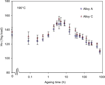
(32) Chapter 2 Literature Review attributed either to both GPII/θ″ and θ′ or to the θ′ phase only [27]. At a given stage of the ageing process, two structures can coexist and contribute to the hardening. 2.2.3.2 Al-Cu-Mg based alloys. Age hardening of Al-Cu-Mg alloys within the (α+S) phase field also occurs in two stages, separated by a hardness plateau over a range of ageing temperatures from 110°C to 240°C [7, 9]. As seen in Fig. 2.9, the first stage of hardening is a rapid hardness increase which occurs within about 1 min of ageing at 150°C. The rapid hardness increase accounts for approximately 50-70% of the total hardness increase. After this rapid rise, the hardness curve exhibits a long plateau during which the hardness remains constant for several hours until a second stage of hardening towards the peak hardness [33, 36]. Natural ageing of Al-Cu-Mg alloys causes an increase in hardness from the as-quenched value to a plateau value. The rate and extent of the hardening depend on alloy composition [9, 41, 70]. It is thought that the natural hardening and the first stage of hardening in artificial ageing curves are due to the same mechanism [39]. The origin of the age-hardening behaviour in Al–Cu–Mg alloys has been extensively studied. It has been generally accepted that the first stage of hardening and the plateau is attributed to the formation of GPB zones, while the second stage of hardening is mainly attributed to the precipitation of the S phase [7, 32]. Recently, since work on the age hardening of an Al-1.1Cu-1.7Mg (at.%) alloy by means of APFIM, TEM/SAD and HREM failed to reveal the GPB zones until near the end of the hardness plateau, Ringer et al.[36] proposed a ‘cluster hardening’ mechanism, related the initial rapid hardening to Cu-Mg co-clusters, and the second hardening to GPB zones. Later, 3DAP data of the same alloy were interpreted to indicate that little or no Cu-Mg co-clusters were present immediately after the first rapid hardening reaction [37, 39]. Based on the observation of additional rapid hardening in the specimen that was first aged for 1min at 150°C to reach the plateau then deformed and re-aged at 150°C, Reich et al. [37] suggested that the rapid hardening is caused by a dislocation– solute interaction, i.e. the locking of existing dislocations due to solute atoms segregated to the dislocations. Nagai et al. [71] employed Coincidence Doppler. 18.
(33) Chapter 2 Literature Review Broadening of positron annihilation radiation (CDB) and positron lifetime spectroscopy techniques to study the vacancies and to identify the solute atoms that are associated with vacancies, i.e. to identify the vacancy-solute complexes in an Al1.7Cu-1.3Mg (at.%) alloy. They suggested that vacancy–Mg complexes, which formed after quenching, rapidly migrate to vacancy sinks and vacancy–Mg–Cu complexes form along dislocations during the first 1 min ageing at 150°C. As this interpretation of the formation of vacancy–Mg–Cu complexes is difficult to reconcile with the interpretation of 3DAP data given by Reich et al. [37] and Ringer et al. [18], which reported that little or no Cu-Mg co-clusters form in this early stage, Nagai et al. [71] considered that their results support the suggestion proposed by Reich et al. [37]. Although the formation of vacancy–Mg–Cu complexes are considered as nucleation sites for coherent clusters and GP zones [72, 73], Ferragut et al. [74] pointed out that CDB and positron lifetime spectroscopy results cannot be used to indicate the origin of the rapid early hardening in Al-Cu-Mg alloys because these results only give information on the local chemistry near the positron annihilation sites such as vacancy-containing solute aggregates. Raviprasad et al. [75] reported the formation of complex multi-component clusters, enriched in Cu and Mg but also containing Si and Ag, in an Al-2.5Cu-1.5Mg-0.4Ag-0.25Si (wt%) alloy aged at 150°C for 5min by 1DAP analysis. They proposed that clustering of Mg-Cu-(Ag-Si) precedes the formation of the GPB zones and contributes to the initial rapid hardening. Ratchev et al. [40] studied the age hardening of an Al-0.6Cu-4.2Mg (wt.%) alloy by HREM and TEM/SAD, and suggested that the initial rapid hardening is caused by both the CuMg co-clusters and the heterogeneous formation of S″ on dislocations. However, HREM results of an Al-1.1Cu-1.7Mg (at.%) alloy aged 5min at 150°C obtained by Reich et al. [37] and of an Al-1.7Cu-1.3Mg (at.%) alloy aged 1min at 150°C obtained by Nagai et al. [71] have shown that no precipitates are present either in the matrix or along dislocations, indicating that the rapid hardening cannot be caused by heterogeneous precipitation of the S″ phase. Using thermal analysis, Zahra et al. [42] insisted that the rapid hardening is due to precipitation of GPB zones, though no direct microstructural evidence for the presence of GPB zones in this stage was reported. Abis et al. [41] studied the early stages of precipitation in an Al-4.4Cu1.7Mg (wt.%) alloy during natural ageing by hardness, DSC and TEM/SAD. Their results showed the presence of the GPB and GP zones with the GPB zones being the 19.
(34) Chapter 2 Literature Review dominating structure. Therefore it was suggested [41] that the classic mechanism [7, 32] should still be accepted, i.e. the initial hardness increase is associated with the formation of GPB zones. More recently, hardness and tensile tests for ageingdeformation-ageing cycles at room temperature have been performed on an Al-1.9Cu1.6Mg (at.%) alloy [76]. The results indicated that no additional age hardening occurs after deformation. In addition, comparison of DSC curves for freshly solution treated samples aged at room temperature for 5min to one week and hardness ageing curves at room temperature showed that a substantial heat release coincides with the natural hardening. This suggests that the increase in hardness is due to the formation of a preprecipitate, and a dislocation–solute interaction mechanism appears unlikely. Using 3DAP, Cu-Mg co-clusters were detected in an Al-1.2Cu-1.2Mg (at.%) alloy and an Al-1.9Cu-1.6Mg (at.%) alloy during natural ageing, while no structure that could be assigned to the GPB zones or S phase is detected [49, 51]. The estimated number density of the Cu-Mg co-clusters showed an increase up to about 4-5h at room temperature. This indicates that the natural hardening is due to the formation of CuMg co-clusters. In summary, the plausible origin of the rapid hardening seems to be a pre-precipitate alternately called GPB zones or Cu-Mg co-clusters. As discussed in Section 2.2.2.2, the distinction between the GPB zones and Cu-Mg co-clusters is not well defined. Following the use of the nomenclature of Cu-Mg co-clusters in Section 2.2.2.2, it is proposed that the rapid hardening is best attributed to Cu-Mg co-clusters. As for the origin of the second stage of hardening, combined experiments of TEM/SAD, DSC and tensile/hardness tests have been carried out on alloys B and D [46, 47, 77]. The results showed that for samples aged at 190°C for 6h and 12h, which correspond to the peak and slightly overaged stages, a dense dispersion of rod or needle shaped precipitates was observed and these precipitates were identified by SAD as being variants of the S phase (Fig. 2.10). For samples aged 12h at 150°C, which corresponds to the onset of the second stage of hardening, TEM revealed only dislocation lines and loops. For samples aged at 150°C for 24h, 48h and 72h, i.e. at the rise to peak strength, faint reflections in the SAD patterns initially indicate the early stages of precipitation of the S phase (150°C/24h); then as the ageing proceeds,. 20.
(35) Chapter 2 Literature Review more S precipitates form and a high density of S precipitates is observed. Consistent with the TEM observations, the S phase precipitation effects in DSC curves decrease with ageing time at 150°C, indicating the formation of S phase prior to DSC runs. This experimental evidence clearly supports the generally accepted view that the second stage of hardening is due to precipitation of the S phase. But Ringer et al. [36] suggested that it is due to the formation of GPB zones. Further discussion by Wang et al. [47] questioned this interpretation and indicated that the peak strengthening is related to the precipitation of S phase regardless of the samples being stretched or not. It is thought that controversies regarding the origin of the hardening in the literature may partly arise from the use of experimental techniques with different resolutions or different techniques focused on the study of different aspects, and may arise from the investigation of different compositions or from the different interpretations of weak diffraction spots.. 2.2.4 Effect of Si on age hardening of Al-Cu-Mg alloys Trace additions of some alloying elements, such as cadmium, indium, tin, silver and silicon, have a marked effect on the age hardening of aluminium alloys, and therefore are of great importance to improve mechanical properties [7, 18, 78, 79]. Many commercial 2xxx aluminium alloys contain Si and Fe either as impurities or as controlled additions. As the presence of Si and Fe cause the formation of coarse intermetallic compounds (e.g. Mg2Si, Al7Cu2Fe and Al12Fe3Si) which are detrimental to fracture toughness, Si and Fe contents are normally kept to a minimum in commercial aluminium alloys. However, several studies have shown that small additions of Si (at levels of 0.1-0.5 wt%) considerably increase the response to age hardening of Al-Cu-Mg alloys at elevated temperature [7, 9, 79, 80], and the 2618 alloy (Al-2.3Cu-1.5Mg-0.2Si-1.1Fe-1.1Ni (wt.%) alloy) was developed for use at elevated temperature based on this effect. It is reported that the presence of Si raises the ageing curves over the entire time scale, particularly with a noticeable increase in plateau hardness [79, 80]. Microstructural examination using TEM by Wilson et al. [55, 79, 81] and by Hutchinson and Ringer [80] revealed that additions of Si suppress the formation of dislocation loops upon quenching and produce a refined dispersion of 21.
(36) Chapter 2 Literature Review S precipitates. TEM images of a Si-free Al-2.62Cu-1.35Mg (wt.%) alloy and a Sicontaining Al-3.98Cu-1.38Mg-0.1Si (wt.%) alloy [44] showed that the sizes of the S precipitates are smaller in the Si-containing alloy under the same ageing condition, and this was attributed to the presence of Si. Wilson et al. [79] reported long sharp streaks in <001>α directions in the SAD patterns of the Si-containing alloys, whereas these streaks were shorter and more diffuse in the Si-free alloys, and suggested that the GPB zones are more stable in the Si-containing alloys. It is however known that streaks are also determined by the precipitate size. Long sharp streaks may indicate more or larger GPB zones in Si-containing alloys. That implies that GPB zones form earlier and grow larger in Si-containing alloys than those in Si-free alloys. TEM/SAD studies of an Al-2.5Cu-1.5Mg (wt%) alloy show no sign of GPB zones after 1h ageing at 200°C [37], while studies of Al-2.5Cu-1.5Mg-xSi (x=0.1-0.5) (wt%) alloys exhibit characteristic diffraction effects attributed to GPB zones after 5min aged at 200°C [80]. Comparison of these results suggests that the addition of Si accelerates the formation of GPB zones. This is further confirmed by Hirosawa et al. [82] on TEM/SAD studies of an Al-1.9Cu-1.7Mg (at%) alloy with and without 0.2Si addition. Contrary to the artificial ageing, the room temperature ageing of Si-containing alloys exhibits a delayed hardening response [79, 80]. The suppressed natural ageing response is understood to be due to the strong binding of the vacancy to the Si atom reducing the free vacancy concentration [79, 80], therefore reducing the rate of the GPB zone formation [79] or the rate of solute diffusion [80]. For enhanced artificial hardening, while attributing the plateau hardness to the GPB zones and the peak hardness to the S phase, Wilson et al. [79] suggested that much of the hardness increase results from the improved strength of the GPB zones, although the refinement of the S distribution also strengthens the alloy. Wilson et al. [79] further suggested that Si may enter into the structure of the GPB zones, and increases the strains associated with the formation of the GPB zones and also their perfection. Recently, using TEM/SAD, HREM and energy dispersive x-ray spectroscopy, Hutchinson and Ringer [80] showed that the peak hardness is dominated by a very fine and uniform distribution of so-called ‘Si-modified GPB zones’, which is rich in Cu and Mg, and containing a trace of Si. Heterogeneous precipitation of the S phase on dislocation helices was also observed. A refined distribution of S phase, which is. 22.
Figure
![Fig. 2.8 Hardness/ageing curves for Al-Cu alloys aged at 110 °C [69].](https://thumb-us.123doks.com/thumbv2/123dok_us/8506579.348970/73.595.141.499.92.351/fig-hardness-ageing-curves-al-cu-alloys-aged.webp)


+7


Related documents
In the present study, we developed a simple and rapid method for the simultaneous measurement of plasma concentrations of four first-line drugs (pyrazinamide,
19% serve a county. Fourteen per cent of the centers provide service for adjoining states in addition to the states in which they are located; usually these adjoining states have
To improve the short-end properties of credit spreads, we model a firm's asset value as a jump-diffusion process.. We show several significant implications of the jump
The cell e.s.d.'s are taken into account individually in the estimation of e.s.d.'s in distances, angles and torsion angles; correlations between e.s.d.'s in cell parameters are
Based on the results of a research conducted for four years in southern Italy on a shallow sandy clay loam (0.30 m), lying on bedrock characterized by fissured limestone,
Our study successfully implemented a referral program for maternal contraceptive services within pediatric care by having pediatric residents assess postpartum women ’ s needs
It was decided that with the presence of such significant red flag signs that she should undergo advanced imaging, in this case an MRI, that revealed an underlying malignancy, which
In Afghanistan, this is a qualification through either the Institute of Health Sciences or the Community Midwifery Education programme.. Skilled
