Integrating Self Testability with Design Space Exploration by a Controller based
Estimation Technique
M. S. Gaur and M. Zwolinski
School of Electronics and Computer Science,
University of Southampton, Southampton SO171BJ, UK.
msg00r|[email protected]
Abstract
Recent research for testable designs has focussed on in-serting test structures by re-arranging an Register-Transfer-Level (RTL) data path generated from a behavioural de-scription to make more testable. Although it can be argued that good results have been obtained with such approaches, we must keep in mind that with the emergence of commer-cial behavioural synthesis tools it is difficult for the designer to understand an automatically generated structural RTL description. With the ever increasing complexity and pres-sure to shorten time to market, test synthesis must not be dissociated from design synthesis. This paper shows that it is possible to generate optimised self-testable RTL when ad-dressed at the highest level of abstraction ie., behavioural description. This is achieved by developing a novel and accurate Built-In Self-Test (BIST) resource estimation tech-nique based on exploitation of certain characteristics of the controller of the design.
1
Introduction
Transistor densities of digital integrated circuits have out-paced designer productivity during the last decade. Computer Aided Design (CAD) tools are not able to catch up the with the system on chip (SOC) design targets [2]. One of the promising ways for bridging this gap is increas-ing the level of abstraction at which the designs are speci-fied. Higher-level abstract descriptions can be much shorter than RTL and gate level descriptions for the same function-ality. Therefore, it is more productive in cost and design time to describe complex SOCs at the behavioural abstrac-tion level.
Users, tool providers and researchers cannot agree on what exactly a behavioural description is. Therefore, for a designer who has always used schematic entry at the gate level, a hardware description language (HDL) at RT level is very abstract. For behavioural synthesis, the input is an algorithmic description and the output is at the RT level.
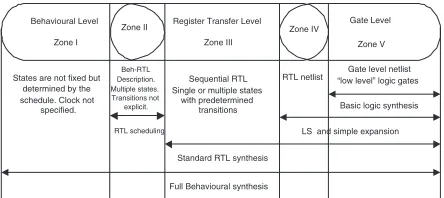
Behavioural Level Zone I
Register Transfer Level Zone III
Gate Level Zone V
States are not fixed but determined by the schedule. Clock not
specified.
Beh-RTL Description. Multiple states. Transitions not explicit.
Sequential RTL Single or multiple states
with predetermined transitions
RTL netlist “low level” logic gatesGate level netlist
Basic logic synthesis
LS and simple expansion
Standard RTL synthesis
RTL scheduling
[image:1.612.315.537.196.295.2]Full Behavioural synthesis Zone II Zone IV
Figure 1. Abstraction levels during synthesis.
While the level of abstraction for design synthesis has been progressing in last few years, the targeted domain for test is still the post RT level. The conventional self-testability issues as addressed post-RTL could not exploit the design space created by the behavioural domain search methods. In this work, we are addressing the self testability of the design simultaneously with the design synthesis in an in-cremental design synthesis frame work.
Automatic insertion of BIST into RTL data-path descrip-tion has been the subject of intensive research over the last few years with considerable success [4, 6, 7, 9]. But the approaches have addressed different levels of abstraction. The approaches of [4, 7] addressed the testability optimi-sation at the zone III of Figure 1, while the methods pub-lished by [6, 7] operated on zones II and III. Other pubpub-lished works like that of [8] gave constructive approaches. These approaches did not address self-test at the highest level of abstraction i.e., zones I-II of Figure 1. We address testa-bility at this abstraction, while the design space is being explored.
our method and Section 6 presents the results of the tech-nique on benchmark designs. The last section concludes our work with a few pointers to the future work.
2
Motivation
Testing has become a major problem over the past two to three decades. While the number of I/O pins for most VLSI devices has increased by an order of magnitude, the number of transistors contained in many VLSI devices has increased by four orders of magnitude [3]. BIST offers vertical testa-bility, an inherent high diagnostic resolution and testabil-ity at all levels as major advantages and has become as a promising solution for high-speed, deep sub-micron VLSI circuits.
Traditionally, the testability insertion phase comes af-ter functional logic synthesis and verification in the VLSI design cycle. This creates two separate optimisation pro-cesses : functional optimisation and BIST insertion and op-timisation. The first deals with functional design behaviour, while the second deals with self test behaviour. In exist-ing VLSI design flows, test structures are inserted after the functional design is complete [5]. This can lead to unac-ceptable performance degradation, forcing a redesign of the system or re-synthesis for test [8].
In essence the global quality of a BISTed design will suf-fer unless testability is analysed and improved before the RTL structure of the design is finalised, that is, unless testa-bility is improved either before or during synthesis. The first choice consists of improving the testability of the behaviour and then performing synthesis with no regard to testability. As a result, the design space is not explored globally and no trade-offs between area/performance and testability possi-ble.Since we want testability to be taken into account when design choices are taken, we will analyse and improve testa-bility during behavioural synthesis.
The primary motivation for our proposed methodology is :by optimising the functional area and delay at the same time as the testability, can we generate a design that is over-all better than one that has the BIST structures inserted af-ter synthesis? The main contribution of this work is to ex-ploit a unified design space wherein a very large number of equivalent designs are assessed to achieve a target design
specification with ensuredself-testability.
2.1
An Example
The main task of design space exploration during be-havioural synthesis is to evaluate a large number of designs in terms of a cost vector defined by design parameters. To do this, it is necessary to consider the times at which oper-ations are scheduled and the modules to which these opera-tions are bound. Functional scheduling has a great influence on resource sharing leading to a bound structure. Functional scheduling affects BIST resources in two ways : Firstly, it determines the lifetimes of the variables and hence affects
A
E D C B A
+2, +4 +1, +3
TPG TPG SA
(b)
F
A C E D
+4 D C B
+3 +2 +1 A
(c) (a)
A
+1 B
+2,+3,+4 C
[image:2.612.314.537.18.205.2]E, F D
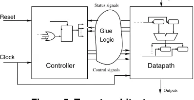
Figure 2. CDFG and two of the allocations.
the register assignment solution space. Secondly, it deter-mines temporal sequences of operations and hence affects functional unit (FU) assignment solution space.
The BIST resources minimisation problem is to de-cide which registers to modify and the modes to add – PTPG (Pseudo random Test Pattern
Genera-tor), MISR (Multiple Input Signature Register), or
BILBO (Built-In Logic Block Observer), in such a way that every FU in the given data path can be tested with min-imum area overhead incurred by addition/modification of registers. Every such configuration of FUs is called a BIST
embedding (BE). Further details for the assumptions and
constraints can be found in [12]. To illustrate the advantages of this approach, consider the scheduled data flow graph in Figure 2. Two allocations have been performed as shown in Figures 2 (B) and (C). Two possible BIST embeddings for the data path are shown in Figure 3 illustrating the test area and test time requirements. If we compare the test area over-heads of these two configurations, we observe that the data path of Figure 2 (B) will need the following test resources: 1 Concurrent Built In Logic Block Observer (CBILBO),
3 PTPG, 1 MISRand the allocation of the Figure 2 (C)
will require 3 PTPG, 1 MISR. The test resources needed
for the first allocation are greater than those for the sec-ond, but only one test session is needed compared with two. A more complex test controller would also be needed for two test sessions. This example highlights the existence of trade-off of testability with functional design parameters. This trade-off can only be exploited during a unified design space exploration while design behaviour is mapped to an
RTL structure.If the test allocation is done after the
archi-tecture is fixed, this choice remain unexplored.
3
BIST Cost Estimation
For BIST insertion and optimisation, approaches have
over-TPG TPG
(b) SA
(a)
{3P, 1M}
A A
D
B = 0
+1, +3 +2, +4
+1, +3 +2, +4
C
E E
B D = 0 C
Test Session II TPG TPG
SA
Test Session I
+2,+3,+4 +1
CB
{1C, 3P, 1M} E, F
D C TPG
B A
[image:3.612.62.274.26.281.2]SA TPG TPG
Figure 3.Self-testableconfigurations of the
al-locations in Figure 2.
head solution (MAOS) or the minimal test (application) time solution (MTTS). Both approaches have merits and limitations. The MAOS-oriented approaches focus on min-imising the area overhead. The basic approach is to max-imise the sharing of test registers resulting in fewer number of registers being modified for BIST [1, 8]. It is observed that in the behavioural synthesis and optimisation process, every design iteration needs to evaluate an appropriate cost vector corresponding to the design optimisation state [11]. When considering a particular instance of a design, the CDFG generates a new structural definition by the trans-form application. This definition also gives us an estimate of BIST cost vector in addition to the area/performance of design. BIST resources, as referred to in our discussion, are the BIST area overhead and the test time requirement for the structure of a given data path.
4
Unified Design Space Exploration
We address testability while we explore design space generated by the design behaviour. By considering opti-misation of BIST resources during high-level synthesis two objectives are achieved: 1) a data path with lower BIST area overhead and total area is synthesised with a control on the test time, and 2) the design cycle time is reduced because iterations due to violation of design constraints after BIST insertion may no longer be necessary.
BIST cost as explained in the section 3 is defined by the
Minimal area overhead design design space Representaive Test design space design
test time Minimal
max min
t
A
rea
Delay
initial
final
initial
final Delay
Delay
Area
Area
Functional design space
configuration Final frozen configuration Initial design (Maximally serial) t
synthesis behavioural design during Trajectory of
Area overhead
Test time
Intermediate design’s search space for self−testability
Figure 4. Unified testable design space.
structure of the design which can only be extracted from an RTL structure for the given behaviour. And the prob-lem is compounded by the fact that a given behaviour can
be mapped tomany equivalent RTL designs. Extraction of
such cost may be computationally expensive for complex designs. A designer can explore and examine many (possi-bly millions) of different implementations while searching for an optimal design [11]. We have employed a
frame-work, MOODS1[11] which is incremental in operation : the
design space is explored using a set of transforms. Trans-forms [11] are a set of behaviour-preserving incremental changes in the CDFG for scheduling, allocation, and bind-ing. The solution space search can be tailored with user-defined multiple objective design constraints. In our
frame-work, we assume that a total of transforms are applied
and represents an intermediate design within the
solu-tion space, with FUs, the following expression describes
the size of an integratedself-testabledesign space:
As has been explained in section 2.1, every FU in turn
can have a number of potentialself-testableconfigurations
at every intermediate design step calledBEs. The unified
expanded search space is depicted in Figure 4.
In contrast, BIST insertion at structural RTL permits lim-ited exploration of the available design space defined by an
RTL structure. This design space is given by
.
This property of such methods may limit the active trade-off
capability for betterself-testabledesigns.
1 ultiple
[image:3.612.339.514.30.230.2]5
Controller based Estimation
In this section, we explain how we implement our method. For a given behavioural description, the number of instructions implementing the CDFG remain invariant. What does change during optimisation and synthesis is the sequencing of these instructions and the FUs implementing them. The sequencing is easier to capture from the control states but is not obvious from data paths. Whereas, if we
observe only the data path it carries noa-prioriinformation
about partitioning which can be utilised for BIST resource estimation. Hence, the estimation of BIST resources is quite cumbersome if considered only by the structure of a com-plex data path.
Within a behavioural description, variables relate to the storage and contribute to potential BIST resources and the maximal independent operation set relates to the module under test.
In our incremental framework, we found that the BIST resources estimation and optimisation can also be per-formed efficiently in an iterative incremental way. A trans-form depicts a small step within the design space and its application creates one successful move within the design synthesis trajectory. The design data and transform selec-tion is done with the help of user objectives and priorities and driven by an optimisation routine working on the cost vector function. The nature of the transforms places them
ideally as aself-testestimation tool within a unified design
space of Figure 4. We can estimate BIST costs transform-wise on the global data path from the controller definition.
5.1
Target Architecture
The behavioural synthesis system targets a distributed control plus data path architecture. It is generated by the instructions which are compiled from the behavioural de-scription of the design.
The data path is implemented by a distributed network of FUs, registers and multiplexors with the flow of data directed through the control of register loading and multi-plexor selects via control signals. For each data-flow node there is a corresponding controller state. The reverse is not necessarily true. This architecture has the following prop-erties :
¯ Each control state is implemented by a special control
register which generates signals to drive the next state logic and to control the data path.
¯ The system clock connects to every register and
con-trol state in the circuit.
¯ Execution of instructions is controlled via the load
en-able on the instruction output registers.
The generic form of the target architecture is shown in Figure 5. It forms a coherent multi-level description link-ing both design behaviour and structure and it is capable of
Clock Reset
Controller Datapath
Inputs
Logic Glue
Status signals
Control signals
[image:4.612.327.526.30.133.2]Outputs
Figure 5. Target architecture.
describing a design at allstages throughout the synthesis
process.
5.2
Transform Example
In this section with the help of transform application ex-amples we illustrate the effects on the structure which affect the self-test attributes of the data path. As explained in the earlier section 4, the core optimisation algorithm works on the instructions implementing the behaviour. To provide for multiplicity of optimisation strategies, a broad set of general transforms is provided . They allow both design improve-ment and degradation, necessary to allow hill climbing out of local minima during optimisation. The problems associ-ated with the premature binding is addressed by this feature, which is encountered in other systems which perform syn-thesis sub tasks in a fixed sequential order.
To illustrate the cost trade-off and estimation efficiency,
now we use one of the scheduling transformsgroup
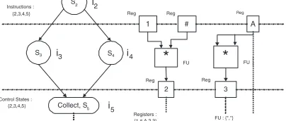
instruc-tions on register as an example. This transform is geared towards removing registers in the data path with one input and one output arc : for removal of temporary variables. An attempt is made to merge the group of instructions contain-ing the writcontain-ing instructions into the readcontain-ing control state. If successful, the intermediate register may be bypassed. For the testability purposes we also check whether the regis-ter implemented by the variable is used in any of the test sessions as an input or output register, if not then it will in-dicate the reduction of test area overhead and the test time will increase by the test delay of the group FU. In Figure 6
grouping on register2will merge writing instruction ¿with
the compatible instruction past register2resulting in the
re-moval of the intermediate temporary register.
The example is a representative of the mechanism for the incremental estimation method wherein the test quality parameters trade off is captured accurately and efficiently
at the highest level of abstraction. A set of19transforms
are used for synthesis optimisation during our framework. More details of the transforms can be found in [10].
5.3
The Technique
The proposed technique starts with the creation of a
*
1 #
2
*
3
A
S2
S3 S4
Collect, S5
i3 i4
i2
Reg Reg Reg
Reg Reg
FU FU
i5
Registers :
{1,#,A,2,3} FU : {*,*} Instructions :
{2,3,4,5}
[image:5.612.67.269.34.120.2]Control States : {2,3,4,5}
Figure 6. Partial controller and data path for
group instruction on registertransform.
per variable and one FU per operation. It is anave
imple-mentation, as no attempt has been made to optimise any-thing (neither controller nor data path) at this point. It is the top right point within the unified design space in Figure 4.
The proposed methodology is illustrated in Algorithm 1. It is a greedy heuristic to determine which controller states are preferable during self-test. To this end, an index, , is computed for each state from the information available at the instruction level. The aim is to reduce the cost of BIST resources, hence the minimum number of controller states need to be selected. The following strategy is adopted:
¯ If two controller states cover the same number of
func-tional units, we choose the one with the minimum test time. Alternately if two controller states have same test time, we choose the one which covers the max-imum number of functional units. This explains the
factor
in the computation of .
While selecting a state, it needs to be ensured that this
step will result in the minimum conflict later. If two states do not share any output registers, all the groups in these two states can run concurrently in the same test session. However, if two states share exactly the same set of registers, these can never be scheduled in same test session. There is another possible scenario when two states share only some of the output regis-ters. In this case, some groups from the two states can still be run concurrently provided they do not share the same output register. This explains the second factor
for the
compu-tation of .
This methodology has the following advantages:
Estimationtrulyoperates at thebehavioural level.
The method computationally efficient, as the
testabil-ity estimation is performed locally at the incremental transform design data set (partitioned design space).
On the basis of controller state analysis, BIST
con-troller can be generated easily from the generated spec-ification.
Algorithm 1Predictive BIST resource cost estimation tech-nique from the controller specifications.
Require: Controller path of the design behaviour from di-rectly compiled controller data-path pair.
:
-th controller state,
:
-th functional unit,
:
-th instruction group of
.
: Test time of
.
: Set of output registers for
.
: Set of output registers for
.
foreach controller state
do
end for
Sort states in descending order on .
for do
selectfalse
for
do
if All FUs in
coveredthen
continue.
else if
test session allocatedthen
Select registers.t. group scheduled asap.
Create new session with
else
Selectwith min. sharing across control states.
Add
to an existing session.
end if
selecttrue
end for
ifselect == truethen
Mark
for BIST controller.
end if end for
The direct analysis of the complexity of the proposed heuristic is not very straight forward. We are consider-ing number of FUs of the groups at every controller state. The complexity of the algorithm will be the the product of number of controller states, maximum number of instruc-tion groups per state, maximum number of FUs per group and maximum number of registers per FU. As the upper limits of individual parameter is generally small and also the nature of the implementation is incremental being at-tached with the transforms, it provides very good efficiency in comparison to the earlier constructive method presented in [12].
6
Results
Functional Priorities Area :HighDelay :Low
Design synthesis Without
BEcostDWIB
Design Area Delay
(gates) (ns) (gates)
FFT 38.14 813.4 81.95 QRS 6.944 2582.2 135.86 DHRC 39.286 1911.5 49.80
Design synthesis With Unified
BEcostDWUB
Ý
Design Area Delay (%)
FFT 37.512 998.9 65.76 1.68 QRS 6.722 2409.8 114.76 3.4 DHRC 39.704 1413.5 53.41 -0.98
: BIST Area Overhead
[image:6.612.69.267.26.185.2]Ý: Cumulative Area Improvement
Table 1. BIST overhead comparison.
Design No. of FUs No. of Regs CPU Time (secs)
DWIB DWUB
FFT 54 98 33.8 288.8
QRS 163 255 80.8 5551.1
[image:6.612.60.277.239.301.2]DHRC 100 1530 44.6 111.8
Table 2. Design synthesis statistics
technology library of 0.35 micron. All the area figures are in terms of equivalent gates and the delay in nano-seconds. Table 1 compiles the results for the optimised designs for a given set of user priorities. In the Table 1 columns 2-4 shows the frozen design figures as per the left-bottom of the design space as described in Figure 4, whereas columns 5-7 contains the results when the BIST cost estimations are used as per our estimation criteria. The last column shows the percentage BIST cost improvement. Table 2 shows the synthesis statistics for the designs. Columns 2-3 represents
the initially maximally serial implementation statistics of
FUs and registers and illustrate the size of the design space. As can be observed that the the active trade off of the testability by the proposed heuristic produce better self-testable sets of designs. The important aspect of the
com-parison is thatthe final self-testable designs are not
neces-sarily have the same structure which are designed otherwise without embedded BIST resource cost. The extensive search can result in better optimisation and generation of different self-testable designs for the same behaviour. InFFT, the accumulated design area for the self-testable design is re-duced by 1.68%, the penalty paid is in terms of increased delay of the design. Similarly, for QRS the cumulative area
improvement is 3.4%. The designDHRCcould not achieve
the gain from this heuristic for the given optimisation sched-ule by degrading the design area by almost 1%, but resulted in a faster implementation for the given behaviour.
7
Conclusion and Future Work
The results have shown that, with an efficient BIST cost estimation embedding within an incremental framework, better results can be achieved for generating of BISTed data paths. It is made possible with an efficient and accurate estimators the unified design space. The present heuristic, predictive estimation within the conjoined design space is performed at every iteration, this makes the process slow for big designs. To address this, we plan to introduce an es-timator control heuristic which can choose and steer more efficient application of the self test estimation within the in-tegrated transform loop.
References
[1] L. J. Avra. Synthesis Techniques for Built-in Self-Testable Designs. PhD thesis, Stanford University, 1994.
[2] R. A. Bergamaschi. Bridging the domains of high-level and logic synthesis. IEEE Transactions on VLSI Systems, 21(5):582–596, may 2002.
[3] M. L. Bushnell and V. D. Agrawal.Essentials of Electronic Testing for Digital, Memory and Mixed-Signal VLSI Cir-cuits. Kluwer Academic Press, Boston, USA, 2000. [4] I. Ghosh, N. K. Jha, and S. Bhawmik. A BIST scheme for
RTL circuits based on symbolic testability analysis. IEEE Transactions on CAD, 19(1):111–128, 2000.
[5] X. Gu, K. Kuchinski, and Z. Peng. An efficient and eco-nomic partitioning approach for testability. InProceedings IEEE International Test Conference (ITC), pages 403–412, Washington DC, 1995.
[6] J. C. M. Nourani and C. Papachristou. Integrated test of interacting controllers and datapaths. ACM Transactions on Design Automation of Electronic Systems, 6(3):401–422, 2001.
[7] N. Nicolici, B. M. Al-Hashimi, A. D. Brown, and A. C. Williams. BIST hardware synthesis for RTL data paths based on test compatibility classes. IEEE Transactions on Computer-Aided Design, 19(11):1375–1385, November 2000.
[8] I. Parulkar, S. K. Gupta, and M. A. Beuer. Introducing re-dundant computation in RTL data paths for reducing BIST resources. ACM Transactions on Design Automation of Electronic Systems, 6(3):423–445, 2001.
[9] C. P. Ravikumar, S. Gupta, and A. Jajoo. Synthesis of testable RTL designs. InProceedings IEEE International Conference on VLSI Design (ICVD), pages 187–192, 1998. [10] A. C. Williams. A Behavioural VHDL Synthesis System
using Data Path Optmisation. PhD thesis, University of Southampton, Southampton, UK, 1997.
[11] A. C. Williams, A. D. Brown, and M. Zwolinski. Simul-taneous optimisation of dynamic power, area and delay in behavioural synthesis. IEE Proceedings on Computers and Digital Techniques, 147(6):383–390, November 2000. [12] M. Zwolinski and M. Gaur. Integrating testability with