UNIVERSITI TEKNIKAL MALAYSIA MELAKA
STUDY OF FLUID FLOW IN JUNCTION OF CAR WASHER
TUBE USING CFD SIMULATION
This report submitted in accordance with requirement of the Universiti Teknikal Malaysia Melaka (UTeM) for the Bachelor Degree of Mechanical Engineering
Technology
(Automotive Technology) (Hons.)
by
MUHAMMAD HAFIZ BIN ABDULLAH B071310422
911121-14-5319
iii
DECLARATION
I hereby, declared this report entitled “Study of fluid flow in junction of car washer tube using CFD simulation” is the results of my own research except as cited in references.
Signature : ………..
Author’s Name : Muhammad Hafiz Bin Abdullah
iv
APPROVAL
This report is submitted to the Faculty of Engineering Technology of UTeM as a partial fulfilment of the requirements for the degree of Bachelor Degree of Mechanical Engineering Technology (Automotive Technology) with Honours. The member of the supervisory is as follow:
v
ABSTRACT
vi
ABSTRAK
vii
DEDICATIONS
viii
ACKNOWLEDGMENTS
I am sincerely appreciative and grateful to my supervisor Ms Najiyah Safwa Binti Khashi’ie for giving me chances and opportunity to et involved in this project. A lot of thanks to her for her ideas, guidance, supports and encouragements in making this research possible. I am thankful to her for the time spent on correcting and proofreading my mistakes in writing this Project Sarjana Muda (PSM) thesis.
My sincere thanks to my lecturer, Mr Mohd Afdal Bin Shamsudin for guidance and dedication in teaching me for the writing of this thesis and how to use the software. Without the help of my supervisor and him, it is possible for me to complete this project on time.
Thanks to my beloved parents, Abdullah Bin Ahmad and Mrs Noraini Bt Bujang who always support me and give me courage since the beginning of this project. Their words have given me strength to complete this thesis project. My sincere thanks to all my friends for their support and guidance during the project period.
ix
TABLE OF CONTENT
DECLARATION ... iii
APPROVAL ... iv
ABSTRACT ... v
ABSTRAK ... vi
DEDICATIONS ... vii
ACKNOWLEDGMENTS ... viii
TABLE OF CONTENT ... ix
LIST OF FIGURES ... xii
LIST OF TABLES ... xiv
LIST OF ABBREVIATIONS, SYMBOLS AND NOMENCLATURE ... xv
CHAPTER 1 ... 1
1.0 Introduction ... 1
1.1 Background of the Study ... 1
1.2 Problem Statement ... 2
1.3 Project Objective ... 3
1.4 Scope of Project ... 3
CHAPTER 2 ... 4
2.0 Introduction ... 4
x
2.2 Pipe ... 7
2.2.1 Type of pipe ... 7
2.3 Fluid properties ... 9
2.3.1 Viscosity ... 10
2.3.2 Reynolds number, Re ... 11
2.3.3 Laminar and turbulent flow ... 12
2.3.4 Eddy viscosity ... 14
2.4 Pressure losses ... 14
2.5 Type of turbulence model ... 15
2.5.1 Spalart-allmaras... 15
2.5.2 K-epsilon model ... 15
2.5.3 K-omega model ... 16
2.6 SolidWorks ... 17
CHAPTER 3 ... 18
3.0 Introduction ... 18
3.1 Methodology Flow Chart For PSM ... 19
3.1.1 Identify the measurement of the actual washer tube ... 20
3.2 Catia V5 ... 22
3.2.1 Design the washer tube using CAD software ... 23
3.2.2 Computational domain ... 24
xi
CHAPTER 4 ... 27
4.0 Introduction ... 27
4.1 Case Study ... 27
4.2 Redraw pipe in CAD model. ... 28
4.2.1 Redraw existing pipe in CAD model. ... 28
4.2.2 Redraw new structure pipe in CAD model. ... 30
4.3 Simulation and compare fluid flow of design ... 32
4.3.1 T-junction pipe ... 33
4.3.2 Y-junction (15°) ... 39
4.3.3 Y-junction (90°) ... 45
CHAPTER 5 ... 53
5.0 Introduction ... 53
5.1 Conclusion ... 53
5.2 Recommendation for Future Study: ... 54
REFERENCES ... 55
xii
LIST OF FIGURES
Figure 2.1: washer tube are located under the front bumper... 5
Figure 2.2: T type of washer tube ... 6
Figure 2.3: Y type of washer tube ... 6
Figure 2.4: Elbow type of washer tube ... 6
Figure 2.5: Example possibilities of fluid (liquids or gasses) flow inside and outside the junction (Vasava, 2007). ... 8
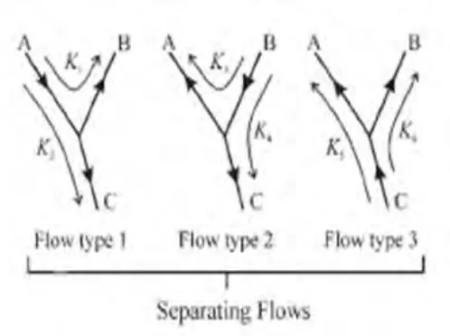
Figure 2.6: Possibilities of split fluid flow in the junction (Bassett, Winterbone and Pearson, 2001). ... 8
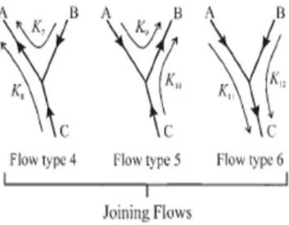
Figure 2.7: Possibilities of combining fluid flow in the junction (Bassett, Winterbone and Pearson, 2001). ... 9
Figure 2.8: The behavior of colored fluid injected into the flow in laminar flows in a pipe (Page, 2004). ... 12
Figure 2.9: The behavior of colored fluid injected into the flow in turbulent flows in a pipe (Page, 2004). ... 13
Figure 3.1: The flow Chart of Methodology ... 19
Figure 3.2: Vernier caliper ... 20
Figure 3.3: T type of washer tube ... 21
Figure 3.4:Y type (15°) of washer tube ... 21
Figure 3.5: Y type (90°) of washer tube ... 22
Figure 3.6: Example of workbenches use in CATIA V5R20 (Cozzens, 2013) ... 23
Figure 3.7: Summary information box of mesh analysis. ... 25
Figure 4.1: Existing T-tube CAD model ... 29
Figure 4.2: Existing Y-tube (15°) CAD model ... 29
Figure 4.3: Existing Y-tube (90°) CAD model ... 30
Figure 4.4: Modified T-tube CAD model ... 31
Figure 4.5: Modified Y-tube (15°) CAD model ... 31
Figure 4.6 : Modified Y-tube (90°) CAD model ... 32
Figure 4.7: T-junction existing tube ... 33
Figure 4.8: T-junction modified tube ... 33
xiii
Figure 4.11: Surface plot of pressure T-junction existing tube ... 35
Figure 4.12: Surface plot of pressure in T-junction modified tube ... 35
Figure 4.13: The point parameter for T-junction existing tube (blue dot) ... 36
Figure 4.14: The point parameter for T-junction modified tube (blue dot) ... 37
Figure 4.15: Y-junction (15°) existing tube ... 39
Figure 4.16: Y-junction (15°) modified tube ... 39
Figure 4.17: Flow trajectories of velocity in Y-junction (15°) existing tube. ... 40
Figure 4.18: Flow trajectories of velocity in Y-junction (15°) modified tube ... 40
Figure 4.19: surface plot of pressure in Y-junction (15°) existing tube ... 41
Figure 4.20: surface plot of pressure in Y-junction (15°) modified tube ... 42
Figure 4.21: The point parameter Y-junction (15°) ... 43
Figure 4.22: The point parameter Y-junction (15°) modified tube ... 44
Figure 4.23: Y-junction (90°) existing tube ... 46
Figure 4. 24: Y-junction (90°) modified tube ... 46
Figure 4.25: Flow trajectories of velocity in Y-junction (90°) existing tube. ... 47
Figure 4.26: Flow trajectories of velocity in Y-junction (90°) modified tube ... 47
Figure 4.27: Surface plot of pressure in Y-junction (90°) existing tube ... 48
Figure 4.28: Surface plot of pressure in Y-junction (90°) modified tube ... 48
Figure 4.29: The point parameter Y-junction (90°) existing tube ... 49
xiv
LIST OF TABLES
Table 2.1: The ranges of the reynold number (Walski, 2001). ... 12
Table 4.1: Point parameter at T-junction tube ... 37
Table 4.2: Point parameter at T-junction modified tube ... 38
Table 4. 3: The different amount of pressure at both T-junction tube ... 38
Table 4.4: Point parameter at Y-junction tube ... 43
Table 4.5: Point parameter at Y-junction (15°) modified tube ... 44
Table 4. 6: The different amount of pressure at both Y-junction (15°) tubes ... 45
Table 4.7: Point parameter at Y-junction (90°) existing tube pipe ... 49
Table 4.8: Point parameter at Y-junction (90°) modified tube ... 50
Table 4.9: The different amount of pressure at both Y-junction (90°) tubes ... 51
xv
LIST OF ABBREVIATIONS, SYMBOLS AND
NOMENCLATURE
CAD - Computer Aided Design
CATIA - Computer Aided Three-Dimensional Interactive Application CFD - Computational Fluid Dynamics
K - K-epsilon
K - Kelvin
m - metre
mm - millimetre m/s - metre per second
Re - Reynold Number
SA - Sparlart-allmaras
SST - shear stress transport
Pa - Pascal
- shear stress
- absolute (dynamic) viscosity
dy
dV - time rate of strain
1
CHAPTER 1
INTRODUCTION
1.0 Introduction
This section will introduce the study of fluid flow in junction car washer tube using CFD simulation. The first section will discuss the fluid flow, type of car washer pipe and CFD simulation. The second section is problem statement. The third section is objectives of study. Lastly, is about the scopes of study.
1.1 Background of the Study
Wiper is a component that used to clean the raindrops or any water at the windscreen. Wipers are made and designed to make driver sight clear and driver concentration during the driving to see the road at windscreen. Most of cars have one viper on the rear window, two wipers on the windscreen, and the other on each headlight (Hashim et al., 2013).
2 A washer fluid pump for a window cleaning system of an engine vehicle may include a housing with an electromotive drive which is masterminded in the housing, a pump unit which can be driven by the electromotive drive, and a ventilation opening which is arranged in the housing, where in an opening which is arranged on the internal side of the housing is counterbalanced or slanted concerning the ventilation opening (Cited et al., 2003).
Wiper washer hose also known as washer tube is use to flow water from wiper motor and wiper tank to the nozzle hose to dispersed water to the windshield screen. Washer tube diameter bigger than motor hose and nozzle hose to easily connect and to avoid water flow out from the washer tube (Doyle et al., 2012).
1.2 Problem Statement
Wiper system is one of the driving safety systems for a passenger car. Most wipers operate together with a windshield washer; a windshield motor pumps that supplies water from a tank to the windscreen. The fluid is dispensed through small nozzles mounted on the hood. Conventional nozzles are usually used, but some designs use a fluidic oscillator to disperse the fluid more effectively. These various types of washer types of washer tube uses in automotive; type T, Y and L tubes. For example, Mitsubishi mirage used washer T tube while proton saga and Toyota AE101 use Y tube.
3
1.3 Project Objective
a) To redraw a CAD model of washer tube in wiper hose system.
b) To design a new structure of washer tube in wiper hose system and compare with the existing washer tube.
c) To simulate and compare the fluid flow properties in the washer tube of wiper hose system for different car.
1.4 Scope of Project
a) Redrawing a CAD model for branch tube of wiper hose system for different car using CATIA.
b) Designing a new structure of washer tube and compare with the existing washer tube using CATIA.
c) Simulate and comparing the fluid flow properties in the branch tube of hose wiper system for different car using CFD simulation (SolidWorks).
d) Assume the inlet value and pressure for the different car is same.
4
CHAPTER 2
LITERATURE REVIEW
2.0 Introduction
Pipe networks are very familiar in industries, where fluid or gases to be transported from one location to the other. The pressure loss may vary depending on the type of components coming across in the network, the fluid that is being transported through the network and pipe fitting (Hirani et al., 2013).
Besides the pipe, the network also consists of elbows, T-junctions, bends, contraction, expansion, valves, meters, pumps, turbines and many other components that will cause of pressure loss due to change in flow momentum due to friction and pipe components. This means that the inflow of energy change to heat due to friction or energy loss due to turbulence (Vasava, 2007).
Pipe flow, a branch of hydraulics and fluid mechanics, is a type of liquid flow within a closed conduit (conduit in the sense of a means of containment). The other type of flow within a conduit is open channel flow. These two types of flow are similar in many ways, but differ in one important aspect. Pipe flow does not have a free surface which is found in open-channel flow. Pipe flow, being confined within closed conduit, does not exert direct atmospheric pressure, but does exert hydraulic pressure on the conduit (Avila et al., 2011).
5 inside the engine compartment and is supplied to the spray nozzle through a washer tube formed from a resin or a rubber elastomer (Doyle et al., 2012).
2.1 Washer tube
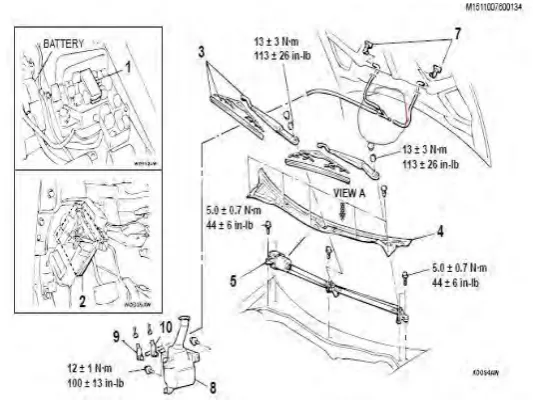
[image:19.595.187.454.366.566.2]Washer tube is an application that used in branched pipe design in wiper system. Washer tube is made from plastic, and their feature does not absorb water and drain the water directly to the wiper washer tube nozzle. The washer fluid is stored in a specified tank inside the engine compartment and is supplied to the spray nozzle through a washer tube formed from a resin or a rubber elastomer (Doyle et al., 2012). Figure 2.1 show the position of washer tube in wiper system that use on this days:
Figure 2.1: washer tube are located under the front bumper
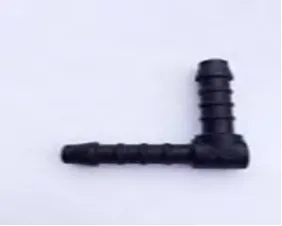
6 2007), pipe network also consists of elbows, T-junctions, bends, contractions, expansions, valves, meters, pumps, turbines and many other components. Washer tube also have this type of shape that using in automotive industries. Washer wiper tube is used determined by the number of nozzle used on a vehicle. Figure 2.2, 2.3 and 2.4 shows T type and Y type are commonly used only to vehicles which has two wiper nozzles and elbow type only used to a vehicle with only one wiper nozzle.
[image:20.595.194.455.405.518.2]Figure 2.2: T type of washer tube
Figure 2.3: Y type of washer tube
[image:20.595.267.408.563.676.2]7
2.2 Pipe
Nowadays, piping is a system of pipes used to deliver fluids such as liquids and gases from one location to another location in industry (Hirani et al., 2013). The type of components coming across in the network, material of the pipe, the fluid that is being transported through the network and pipe fitting are the factors that can occur the pressure losses (Hirani et al., 2013). Fittings are used in plumbing and pipe systems to connect tubing sections or straight pipe, to adapt to different shape or size, and for other purposes, for example for measuring or regulating fluid flow (Singh et al., 2013).
2.2.1 Type of pipe
Tee pipe are used to either dividing or combining a fluid flow. Most common are equal tees which have the junction diameter and equal body but there is also a wide range of decreasing tees where either the body or the junction are different diameter relative to each other (Smith, 2014).
8 the junction (Vasava, 2007).
A wye pipe is where the branch enters the body at an arc and is used to minimize the frictional losses and promote flow in the system. A wye pipe is where the branch is stabbed into the body at an angle (Smith, 2014).
[image:22.595.214.463.301.487.2]Wye pipe fittings are with three openings and are used to create branch lines. A wye tee is where the branch is stabbed into the body at an angle usually 45 degrees and is usually used where the branch is a smaller diameter than the main pipe (Satyendra, 2015).
9 Figure 2.7: Possibilities of combining fluid flow in the junction (Bassett,
Winterbone and Pearson, 2001).
2.3 Fluid properties
10 Fluid viscosity is the property that describes the ability of a fluid to resist deformation due to shear stress (Walski, 2001). For many fluids, most notably water, viscosity is a proportionality factor relating the velocity gradient to the shear stress, as described by Newton's Law of Viscosity at equation 2.1 below:
Eq 2. 1
Where = shear stress
= absolute (dynamic) viscosity
dy dV
Time rate of strain
Viscosity is a measure of the resistance of a fluid which is being deformed by either shear stress or tensile stress. For fluids only, viscosity is "thickness" or "internal friction". Thus, water is "thin", having a lower viscosity, while honey is "thick", having a higher viscosity. Put simply, the less viscous the fluid is, the greater its ease of movement (fluidity) (Kotelnikov et al., 2000).