“ I hereby declare that I have read through this report entitle “Controller Tuning By Using Optimization Technique For An Electro-Hydraulic Actuator System” and found that it has complied the partial fulfillment for awarding the degree of Bachelor of Electrical Engineering (Control, Instrumentation & Automation) With Honors ”
ELECTRO-HYDRAULIC ACTUATOR SYSTEM
SYAIFUL SYHWAN BIN NASRI
A report submitted in partial fulfilment of the requirements for the degree of Control Instrument and Automation
Faculty of Electrical Engineering
UNIVERSITI TEKNIKAL MALAYSIA MELAKA
I declare that this report entitles “Controller Tuning By Using Optimization Technique For An Electro-Hydraulic Actuator System” is the result of my own research except as cited in the references. The report has not been accepted for any degree and is not concurrently submitted in candidature of any other degree.
Signature: ...
ACKNOWLEDGEMENT
In the name of Allah, the Most Beneficent and The Most Merciful. It is deepest sense gratitude to the Almighty that gives me strength and ability to complete this final report. First of all I would like to express my gratitude to my supervisor, Madam Nur Asmiza binti Selamat for his valuable guidance and support throughout this semester until this report completes successfully.
ABSTRACT
ABSTRAK
Pada masa kini, aplikasi yang menggunakan Elektro Hidraulik Penggerak sistem dalam sektor perindustrian telah digunakan secara meluas. Kerana system ini menghasilkan kuasa yang tinggi kepada nisbah berat, saiz yang lebih kecil, dan tindak balas lebih cepat daripada Hidraulik Konvensional Penggerak sistem yang sedia ada. Sistem Elektro Hidraulik Penggerak telah dibangunkan untuk menggantikan sistem Hidraulik Konvensional Penggerak yang mempunyai beberapa masalah seperti kebocoran bendalir kerja, beban penyelenggaraan, berat dan ruang pemasangan yang terhad. Walau bagaimanapun, system Elektro Hidraulik Penggerak telah menghasilkan parameter tak lelurus dan ciri-ciri yang tidak menentu. Walaubagaimanapun, system EHA ini telah menghasilkan system tak terlelurus dan ciri-ciri yang tidak menentu. Oleh itu, untuk meningkatkan prestasi, memerlukan imbagi parameter kepada perubahan dalam system EHA. Dalam projek ini
Proportional Integral Derivative (PID) and Linear Qudratic Regulator (LQR) telah
TABLE OF CONTENT
CHAPTER TITLE PAGE
ACKNOWLEDGEMENT ABSTRACT ABSTRAK i ii iii
TABLE OF CONTENT iv
LIST OF TABLE vii
LIST OF FIGURE viii
1 INTRODUCTION 1
1.1 Introduction 1
1.2 Motivation 2
1.3 Problem statement 2
1.4 Objective of project 3
1.5 Scope of project 3
1.5 Project Outlines 3
2 LITERITURE REVIEW 4
2.1 Introduction 5
2.2 Electro Hydraulic Actuator (EHA) System Background 2.2.1 Description of EHA system background
5
2.3 EHA system operation 6
2.4 Control strategy in the EHA 7
2.5 Application for EHA system 8
2.6 Control of EHA system 9
2.6.1 Proportional, Integral, and Derivative (PID) 2.6.2 Fuzzy logic control
2.6.3 Sliding mode control (SMC) 2.6.4 Adaptive control system
2.6.5 Linear Quadratic Regulator (LQR)
12 13 13 2.7 Optimization technique
2.7.1 Particle Swarm Optimization (PSO) 2.7.2 Genetic Algorithm (GA)
2.7.3 Imperialist competitive algorithm
14 15 15 16
3 METHODOLOGY 18
3.1 Introduction 18
3.2 Flow of the study 18
3.3 Mathematical model of EHA system. 19
3.4 Design LQR and PID Controller 21
3.4.1 LQR Controller 21
3.4.2 PID Controller 24
3.5 LQR and PID Control Tuning using Optimization Technique. 25
3.6 Optimization Technique 26
3.6.1 Particle Swarm Optimization (PSO) technique. 26
3.7 Objective Function 30
3.8 Simulation Process 31
3.9 Disturbance test 33
3.10 Conclusion 35
4 RESULT AND DISCUSSION 36
4.1 Introduction 36
4.2 Expected Open-Loop and Close–Loop from Simulation Result 36
4.3 Selection of PSO parameter 39
4.4 PSO for LQR and PID 39
4.4.1 Parameter for PID and LQR 43
4.5 Comparison between LQR and PID 44
4.61 Parameter for LQR and PID with disturbance 50 4.6.2 Comparison between PID and LQR with disturbance 51 4.7 System response comparison with disturbance and without
disturbance
55
4.8 Conclusion 57
5 CONCLUSIONS 58
5.1 5.2 5.3
Introduction Conclusion Future work
58 58 59
LIST OF TABLE
NO. TITLE PAGE
2.1 Comparison between Kp, Ki and Kd 10
2.2 Function block diagram Fuzzy Logic Controller. 12
3.1 Gantt chart for research methodology 29 4.1 Data transient response for model with step input 37 4.2 Data transient response for model with unity feedback 38
4.3 Number of Particles Selection 39
4.4 LQR data with 10 executions using PSO 41 4.5 PID data with 10 executions using PSO 42
4.6 Parameter value for LQR and PID 43
4.7 Comparison between LQR and PID 46
LIST OF FIGURE
NO. TITLE PAGE
2.1 Schematic of the EHA hydraulic circuit 7
2.2 Control block diagram for the EHA 7
2.3 Injection molding and die casting machines 8
2.4 Wind turbine circuit diagram 9
2.5 The fuzzy logic controller block diagram 11 2.6 The optimization flowchart of GA technique 16 2.7 Flowchart of the propose algorithm 17
3.1 Schematic diagram for LQR 21
3.2 Schematic diagram for PID 25
3.3 LQR Control Tuning block diagram 25
3.4 PID Control Tuning block diagram 26
3.5 Diagram of controller with optimization technique 27
3.6 Flow of chart of PSO technique 28
3.7 Flow of process PSO 32
3.8 Disturbance Input 33
3.9 Disturbance for Signal Input 33
3.10 PID controller system with Disturbance 34 3.11 LQR controller system with Disturbance 34 4.1 Response of the model with step input 37 4.2 Response of the model with unity feedback. 38 4.3 Graph of ITSE versus number of particle for (LQR) with EHA
system
39
4.4 Graph of ITSE versus number of particle for (PID) with EHA system
40
4.6 Graph of ITSE versus number of simulation for PID 42
4.7 Respond for LQR controller 44
4.8 Respond for LQR controller 45
4.9 Comparison System Performance 45
4.10 Performance comparison between LQR and PID controller 46 4.11 Performance index for LQR with disturbance. 49 4.12 Performance index for LQR with disturbance. 50 4.13 Respond for LQR controller with disturbance 51 4.14 Respond for PID controller with disturbance 52 4.15 Combination Respond between PID and LQR controller with
disturbance
52
4.16 Performance comparison between LQR and PID controller with disturbance
53
CHAPTER 1
INTRODUCTION
1.1 Introduction
1.2 Motivation
The application of EHA system technology has spread into many different fields including robotics, aircraft, manufacturing system and etc. Due to higher performance of the EHA system in term of position and pressure the nonlinearities and uncertainties characteristic have to be considered. The intelligent controller tuning will be used in the EHA system to improve the performance of the EHA system. Optimization technique will be used in this project to acquire the best parameter tuning. PID and LQR were chosen to apply in the Electrohydraulic Actuator system. The advantage of using PID which is having a wide range of application in industrial control while the advantages of LQR is the system always be stable and robust.
1.3 Problem Statement
1.4 Objective of Project
The aim of this project is to obtain the parameter for the LQR and PID tuning for Electro Hydraulic System (EHA) using optimization technique. Therefore the objectives are.
1. To implement LQR and PID controller to EHA system and tune controller parameter using PSO.
2. To compare system performance in term of index, Overshoot, Settling Time, Rise Time and precision of the controller.
1.5 Scope of project
In order to achieve the objective of the project, several scopes of project have been outlined: The LQR and PID controller are chosen as the controller of the nonlinearities and
uncertainty model of EHA system.
The LQR and PID parameters will be tuned using optimization technique which is Particle Swarm Optimization.
ITSE will be used as the performance index to the system performance for both LQR and PID will be compare in term of performance index response (Settling Time, Rise Time and Overshoot) and precision.
All simulation work will be shown using MATLAB software.
1.6 Project outlines
CHAPTER 2
LITERATURE REVIEW
2.1 Introduction
This chapter describes the literature review for Electro Hydraulic Actuator (EHA) system. This stage will review related previous work and other related to this project which are EHA system background, EHA system operation, control strategy in the EHA, application for EHA system, controller of EHA systems and lastly optimization technique. The observation from this chapter will determine for the next chapter is a methodology.
2.2 Electro Hydraulic Actuator (EHA) System Background
2.2.1 Description of EHA System Background.
that is being applied in CHA commonly used as power units. In addition, ability to generate very large power compared to their size. The basic function of CHA is to transfer the working fluid and an actuator. Devices that creates a mechanical motion by converting into various form of energy into mechanical energy known as actuator. The problem are faced in CHA system firstly is environmental. The leakage of the working fluid maintenance caused the pollution. In addition, the leakage occurs when high pressure during working fluid. It is between joint of pump, fluid conduits, manifold and fluid conduit. Secondly, the problem is heavy weight. Many parts of hydraulic system are more expensive. It is because the requirement to build and construct need a powerful pressure to operate the requirement system. Lastly is the limited space consumption system CHA. Basically, the system consists of many components and valves to operating. It necessity to improve the system of CHA like size, system maintenance and environmental pollution. EHA system was developed to replace the role of the CHA system with the best performance of the EHA in terms of position, force or pressure is needed [2].
2.3 EHA System Operation
Figure 2.1: Schematic of the EHA hydraulic circuit [5].
2.4 Control Strategy in the EHA
The EHA position control system consist two hydraulic sub-circuit. Which is, outer loop and inner loop, as shown in Figure 2.2. Outer-circuit connected to the symmetrical actuator and an inner-circuit with low-pressure accumulator [6]. Inner loop for control the angular velocity control of the servo motor or pump and outer loop for the position control of the piston [4].Inner loop is an important process because it regulate the electric motor to provide an accurate control into the pump flow. In addition, the friction occurred at pump-motor interface when flow control strategy desensitizes the system into dead-band. The outer loop is an important part in EHA system and to improve the performance and robustness of EHA in term of the position control system.
[image:20.595.91.541.595.738.2]2.5 Application for EHA System.
The use of EHA has spread into many different fields due to their advantages. Recently, with the research and development of the hydraulic control has been developed and used widely in many applications such as manufacturing system, material testing machineries, fatigue testing, flight simulation, paper machines, ship and electromagnetic marine, robotics, and steel and aluminums mill equipment [7].
[image:21.595.155.494.578.737.2]The ability of EHA system such as high power to weight ratio, fast and smooth response characteristic, accurate positioning of heavy load, stiffness response and good power capabilities have increased the number use of EHA in industries. For an example injection molding machines as shown in Figure 2.3. Injection molding machines have several steps that needed to produce a product. The step is clamping, injection, dwelling, cooling, mold opening and removal of products. This method is suitable for production that produces with complicated shapes. Moreover, EHA system is the best way to implement in this method. This is because EHA produces high power to weight ratio and also accurate positioning for plastic processing. In addition, application of wind turbine also implement EHA system. The fundamentals and principles of hydraulic system used for wind turbines, such as for pitch control, yaw control, braking and cooling or filtration systems. For pitch control system, the function is to adjust the pitch turbine blade angle based on Figure 2.4. Basically, the technical feature electrohydraulic pitch control system is precision control, high level of integration, compact design, reliable fail-safe function, integrated safety function and high positioning forces.
Figure 2.4: Wind turbine circuit diagram [21].
2.6 Control of EHA System.
The ability of EHA system, the system become one of the important drive system and play an important role to implement in application in industries. However, the constraints that appearing in EHA system will interrupt the application of the hydraulic control system. The internal and external disturbance that yields the nonlinearities and uncertainties in hydraulic control system. [8]. Thus, this effect will contribute disturbance of performance and degrade the system. To avoid the nonlinearities and uncertainties in EHA system, improve the control performance of EHA by designing a robust controller to compensate the nonlinear behavior of hydraulic system. Although EHA has uncertainty and nonlinearities problem, many researchers have conducted research on performance EHA, due to its advantages.
2.6.1 Proportional, Integral and Derivative (PID)
PID known as Proportional, Integral, and derivative or any combination controller. PID can be implemented in a wide variety of operating systems because of their functional simplicity and reliability. PID controller is designed for controlling the position of the actuator and potential to cope with physical uncertainties and external disturbances[9]. In [32] state that PID controller using tuning method are given better performance compare to conventional PID and it give good performance in term of give less overshoot and less setting time. The PID controller can be tune without approximately model .The ability of PID system can be improve the transient response of the system such as overshoot, rise time, settling time and steady error by tuning parameter PID.
u(t) = KPe(t) + KI ∫ 𝑒(𝑡)𝑑𝑡 + 𝐾𝐷 𝑑 𝑒(𝑡) 𝑑𝑡
𝑡
0
(2.1)
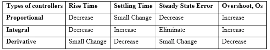
[image:23.595.87.520.526.606.2]From the formula PID, e (t) is error, u (t) is the controller output and Kp, Ki and Kd are the parameter of PID based on equation (2.1). Based on Table 2.1, the comparison between Kp, Ki and Kd to the effect of controller applied on a closed loop system.
Table 2.1 Comparison between Kp, Ki and Kd
2.6.2 Fuzzy Logic Controller
[image:24.595.152.493.365.543.2]The new approach of controller, to overcome the uncertainties and nonlinear problem the fuzzy controller were applied to EHA system. A few of research toward on fuzzy logic control has been done and utilized such as fuzzy with PID and adaptive PID control using fuzzy [17]. Jun et. al [25] presented fuzzy logic self – tuning PID controller to a nonlinear characteristic system for regulating brushless DC motor (BLDC) of EHA system. The nonlinear characteristic that occur such as saturation of the motor power and dead zone due to the statistic friction. The results show, when the Fuzzy controller implemented in EHA system, it can achieve fast response ability without overshoot. In addition, representing, manipulating and implementing a human heuristic knowledge for formal methodology can be provided to control a system performance [8].
Figure 2.5: The fuzzy logic controller block diagram [8]
![Figure 2.1: Schematic of the EHA hydraulic circuit [5].](https://thumb-us.123doks.com/thumbv2/123dok_us/136566.13710/20.595.91.541.595.738/figure-schematic-eha-hydraulic-circuit.webp)
![Figure 2.3: Injection Molding and Die Casting Machines [21].](https://thumb-us.123doks.com/thumbv2/123dok_us/136566.13710/21.595.155.494.578.737/figure-injection-molding-die-casting-machines.webp)
![Figure 2.4: Wind turbine circuit diagram [21].](https://thumb-us.123doks.com/thumbv2/123dok_us/136566.13710/22.595.120.544.70.245/figure-wind-turbine-circuit-diagram.webp)
![Figure 2.5: The fuzzy logic controller block diagram [8]](https://thumb-us.123doks.com/thumbv2/123dok_us/136566.13710/24.595.152.493.365.543/figure-fuzzy-logic-controller-block-diagram.webp)