DESIGN AND DEVELOPMENT OF INTERNET OF THINGS (IOT) ENABLED WHEELCHAIR INCLINATION AND GEOLOCATION FOR
WHEELER REHABILITATION FITNESS ASSESSMENT
LAI MOON CHIN
i
DESIGN AND DEVELOPMENT OF INTERNET OF THINGS (IOT) ENABLED WHEELCHAIR INCLINATION AND GEOLOCATION FOR WHEELER
REHABILITATION FITNESS ASSESSMENT
PROJECT TITLE
LAI MOON CHIN
This Report Is Submitted in Partial Fulfilment of Requirements for The Bachelor Degree of Electronic Engineering (Telecommunication Electronics) With Honours
Fakulti Kejuruteraan Electronic dan Kejuruteraan Komputer Universiti Teknikal Malaysia Melaka
ii
REPORT STATUS DECLARATION
UNIVERSTI TEKNIKAL MALAYSIA MELAKA
FAKULTI KEJURUTERAAN ELEKTRONIK DAN KEJURUTERAAN KOMPUTER
BORANG PENGESAHAN STATUS LAPORAN
PROJEK SARJANA MUDA II
Tajuk
Projek :
DESIGN AND DEVELOPMENT OF IOT ENABLED WHEELCHAIR INCLINATION AND GEOLOCATION FOR WHEELER REHABILITATION FITNESS ASSESSMENT
Sesi
Pengajian : 1 6 / 1 7
Saya LAI MOON CHIN
mengaku membenarkan Laporan Projek Sarjana Muda ini disimpan di Perpustakaan dengan syarat-syarat kegunaan seperti berikut:
1.Laporan adalah hakmilik Universiti Teknikal Malaysia Melaka.
2.Perpustakaan dibenarkan membuat salinan untuk tujuan pengajian sahaja.
3.Perpustakaan dibenarkan membuat salinan laporan ini sebagai bahan pertukaran antara institusi
pengajian tinggi. 4.Sila tandakan ( √ ) :
SULIT* *(Mengandungi maklumat yang berdarjah keselamatan atau kepentingan Malaysia seperti yang termaktub di dalam AKTA RAHSIA RASMI 1972)
TERHAD** **(Mengandungi maklumat terhad yang telah ditentukan oleh organisasi/badan di mana penyelidikan dijalankan)
TIDAK TERHAD
Disahkan oleh:
__ ________________________ ___________________________________
(TANDATANGAN PENULIS) (COP DAN TANDATANGAN PENYELIA)
iii
STUDENT’S DECLARATION
“I hereby declare that the work in this project is my own except for summaries and quotations which have been duly acknowledge.”
Signature : ...
Author : Lai Moon Chin
iv
SUPERVISOR’S DECLARATION
“I acknowledge that I have read this report and in my opinion this report is sufficient in term of scope and quality for the award of Bachelor of Electronic
Engineering Electronic Telecommunication with Honour’s.”
Signature : ...
Supervisor’s Name : DR. Ho Yih Hwa
v
DEDICATION
vi
ACKNOWLEDGEMENT
vii
ABSTRACT
viii
ABSTRAK
ix
TABLE OF CONTENT
PROJECT TITLE ... i
REPORT STATUS DECLARATION ... ii
STUDENT’S DECLARATION ... iii
SUPERVISOR’S DECLARATION ... iv
DEDICATION ... v
ACKNOWLEDGEMENT ... vi
ABSTRACT ... vii
ABSTRAK ... viii
TABLE OF CONTENT ... ix
LIST OF TABLES ... xii
LIST OF FIGURES ... xiii
LIST OF ABBREVIATIONS ... xvi
CHAPTER I: INTRODUCTION ... 1
1.1 Project Introduction ... 1
1.2 Problem Statement ... 3
1.3 Objectives ... 3
1.4 Scope of Work ... 4
1.5 Report Structure ... 5
CHAPTER II: LITERATURE REVIEW ... 6
2.1 Geolocation ... 6
2.2 Internet of Things (IoT) ... 10
x
2.2.2 Device-to-cloud communication model ... 14
2.2.3 Device-to-gateway communication model ... 14
2.2.4 Back-end data-sharing communication model ... 15
2.3 Inclination ... 16
2.4 Bluetooth ... 18
2.5 Related Studies ... 21
2.5.1 Embedded system design for real-time interaction with Smart Wheelchair ... 21
2.5.2 A Novel Multipurpose Smart Wheelchair ... 21
2.5.3 Automated Incline Detection for Assistive Powered Wheelchairs 22 2.5.4 IoT Based Smart Wheelchair with Health Monitoring System 22 2.5.5 A Home Mobile Healthcare System for Wheelchair Users 22 CHAPTER III: METHODOLOGY ... 23
3.1 Flow Chart ... 23
3.2 Hardware and Software Selection ... 25
3.3 Integration of Arduino 101 with NEO6M GPS module ... 29
3.3.1 Hardware Connection ... 29
3.3.2 Software Configuration ... 30
3.4 Building of Mobile Application ... 39
3.5 Web User Interface (UI) for Geolocation Routing ... 45
3.6 Chapter Summary ... 48
CHAPTER IV: RESULT AND DISCUSSION ... 49
4.1 Hardware Connection ... 49
4.2 Inclination Result ... 50
4.3 Geolocation Result ... 54
xi
4.5 Web UI Result ... 61
4.6 Chapter Summary ... 63
CHAPTER V: CONCLUSION AND RECOMMENDATION ... 64
5.1 Conclusion ... 64
5.2 Project Impact and Sustainability ... 65
5.3 Project Limitation and Future Improvement ... 66
REFERENCE ... 67
APPENDICE A- CODING FOR ARDUINO 101 ... 72
APPENDICE B1- “app.module.ts” CODING ... 76
APPENDICE B2- “app.component.ts” CODING ... 77
APPENDICE B3- “home.ts” CODING ... 78
APPENDICE B4- “index.html” CODING ... 84
APPENDICE B5- “home.html” CODING ... 85
xii
LIST OF TABLES
Table 3-1: Comparison between Arduino 101 and Arduino UNO 26 Table 3-2: Comparison of GPS modules in the market 27 Table 3-3: Pin connection to Arduino 101 for GPS module 29
xiii
LIST OF FIGURES
Figure 1: Causes of SPI since the year of 2010 2
Figure 2.1: Basic principle of GPS Navigation 7
Figure 2.2: 24-slot arrangement of GPS satellites 9 Figure 2.3: Control station of GPS over the globe[13] 9
Figure 2.4: Concept layer of IoT 11
Figure 2.5: Device to device communication model 13
Figure 2.6: Device to cloud communication model 14
Figure 2.7: Device to gateway communication model 15 Figure 2.8: Back end data sharing communication model 16 Figure 2.9: Internal operational view of a gyroscope sensor[20] 17 Figure 2.10: Tilt angle calculated from three-axis accelerometer. 17
Figure 2.11: Axis reference for IMU 18
Figure 2.12: GATT profile hierarchy[24] 20
Figure 3.1: Flow chart of project 23
Figure 3.2:Flow Chart of project 24
Figure 3.3: Project Block Diagram 25
Figure 3.4: Difference between Native, HTML5 and Hybrid Application 28 Figure 3.5: Physical connection of NEO6M to Arduino 101 29
Figure 3.6: Importing IMU library 30
Figure 3.7: Global declaration of parameter for inclination data 30 Figure 3.8: The setup loop for acquiring inclination data 31 Figure 3.9: Getting gyroscope and accelerometer data 31
Figure 3.10: Computing accelerometer angle 31
Figure 3.11: Computing angular angle from gyroscope 32 Figure 3.12: Applying Complimentary First Order filter 32 Figure 3.13: Block diagram for Complimentary Filter[35] 33
Figure 3.14: Data updated with latest value 33
xiv Figure 3.16: Importing libraries for extracting geolocation data 34 Figure 3.17: Global parameter declaration for geolocation data 34 Figure 3.18: The setup loop for geolocation data extraction 35 Figure 3.19: Loop function to extract geolocation data 35
Figure 3.20: Importing CurieBLE library 36
Figure 3.21: Declaring BLE service and characteristic parameter 36 Figure 3.22: Setup of BLE service and characteristic UUID 37
Figure 3.23: Setting Union for float data type 37
Figure 3.24: Function loop for emitting data via BLE 38 Figure 3.25: Writing updated value to respective characteristic 38 Figure 3.26: Importing native plugin to “app.module.ts” 39
Figure 3.27: Alert user to enable BLE 40
Figure 3.28: Implementing Google API key 40
Figure 3.29: Scan button implementation 40
Figure 3.30: Scan function for Mobile Application 41 Figure 3.31: Button for found devices connection 41 Figure 3.32: Function connecting device with mobile application 41 Figure 3.33: Function for mobile application to receive data 42 Figure 3.34: Disconnect function to end BLE connectivity 43 Figure 3.35: Button to load Google Map on mobile application 43 Figure 3.36: Function to load Google Map on mobile application 43 Figure 3.37: Import Socket.IO Client library in “home.ts” 44 Figure 3.38: Establishment of Socket.IO connection to Azure server 44 Figure 3.39: Emit event for heart rate and inclination data 44
Figure 3.40: Emit event for geolocation data 45
Figure 3.41: Emit event for mileage data 45
Figure 3.42: Importing API Key and Socket.IO library 46
Figure 3.43: Mode of transportation 46
Figure 3.44: Function initiating Google Map 47
Figure 3.45: Geolocation routing calculation and display 47 Figure 4.1: Physical connection of NEO6M GPS module to Arduino 101 49 Figure 4.2: Mounting of integrated hardware on wheelchair 49
Figure 4.3: Sensor orientation on Arduino 101 50
xv Figure 4.5: Inclination result when wheelchair on static 51 Figure 4.6: Inclination data when wheelchair propel over a stone 51 Figure 4.7: Inclination data on outdoor smooth pavement 52
Figure 4.8: Inclination data on tar surface 52
Figure 4.9 Inclination data propelling wheelchair over inclined terrain 53 Figure 4.10: Inclination data propelling wheelchair over declined terrain 53 Figure 4.11: Geolocation result at front of FKEKK 55 Figure 4.12: Geolocation result at open field behind of FKEKK 55 Figure 4.13: Geolocation result at rooftop of FKEKK 56 Figure 4.14: Geolocation result at centre of FKEKK 56 Figure 4.15: First UI loaded by mobile application 58
Figure 4.16: Toast window to enable BLE 58
Figure 4.17: UI to establish BLE connectivity 59
Figure 4.18: Mobile application aggregated with multiple BLE devices 59
Figure 4.19: Data successfully sent to server 60
Figure 4.20: Geolocation feature of mobile application 61 Figure 4.21: User permission for location sharing 61
Figure 4.22: Geolocation routing on web UI 62
xvi
LIST OF ABBREVIATIONS
ADC Analogue to Digital Converter API Application Program Interface
ATT Attribute Profile
BLE Bluetooth Low Energy
CSS Cascading Style Sheet
DOF Degree of Freedom
EXIF Exchangeable Image File Format
FKEKK Fakulti Kejuruteraan Elektronik Dan Kejuruteraan Komputer GATT Generic Attribute Profile
GLONASS Globalnaya Navigazionnaya Sputnikovaya Sistema GPS Global Positioning System
HTML Hypertext Markup Language HTTP Hypertext Transfer Protocol I2C Inter-Integrated Circuit IAB Internet Architecture Board
IDE Integrated Development Environment IIoT Industrial Internet of Things
IMU Initial Measurement Unit
IoT Internet of Things
IP Internet Protocol
JSON JavaScript Object Notation MAC media access control MCS master control station
PCL Point Cloud Library
PNT positioning, navigation, and timing
RF radio frequency
RFID Radio Frequency Identification RGB-D Red Green Blue - Depth
ROS Robot Operating Systems
SCI Spinal Cord Injury
SIG Special Interest Group SPI Serial Peripheral Interface
TS Typescipt
TTFF Time to First Fix
UART Universal Asynchronous Receiver/Transmitter
UAV Unmanned Aerial Vehicle
xvii
US United State
1
CHAPTER I
INTRODUCTION
This chapter introduce the overall concept of the project. The objectives and problem statement will be discussed. This chapter also included the scope of work for this project. Moreover, a brief discussion on methodology will be included. The overall structure of this report will be explained in this chapter.
1.1 Project Introduction
According Wealth Health Organization (WHO), rehabilitation of people with disabilities is a process aimed at enabling them to reach and maintain their optimal physical, sensory, intellectual, psychological and social functional levels. The purpose of rehabilitation is to optimise patient's sensory, physical, and mental capabilities that were lost because of severe injuries, illnesses, or diseases to attain independence and self-determination. Besides, rehabilitation integrate patient back into the lifestyle activities that they have chosen, whether it is at home, work or leisure. Training for patient to compensate for deficits that cannot be reversed medically also included in the rehabilitation treatment. Treatment should start as soon as possible to speed up recovery. It is prescribed after many types of injury, illness, or disease, including amputations, neurological problems, brain injuries, stroke, and spinal cord injuries.[2]
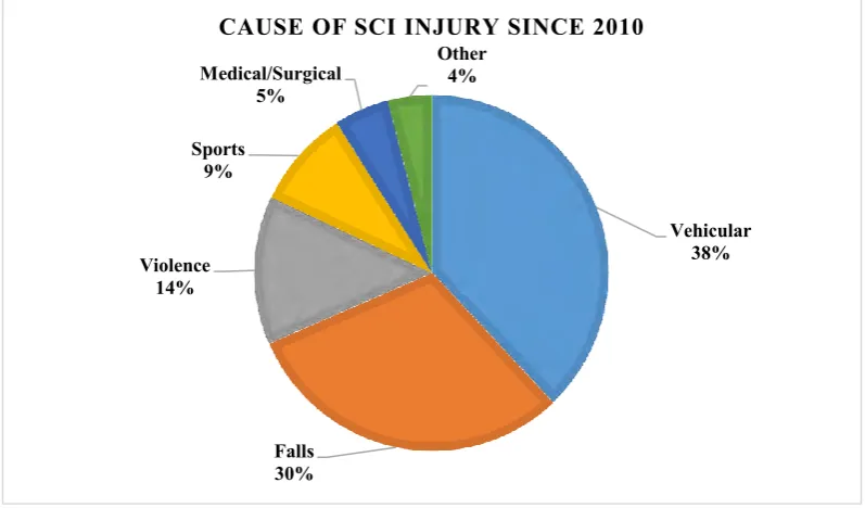
2 has accounted approximately 80% of the SCI cases. The healthcare cost and living expenses of a SCI person vary greatly based on education, neurological impairment, and pre-injury employment history. It is estimated an average cost of $72,047 dollars will be spent by a SCI person per year in 2015. Currently, vehicle crashes are the leading cause of injury, followed by falls, acts of violence and sport injury.[3]
Figure 1: Causes of SPI since the year of 2010
To date, there is still no cure for SCI.[2] Hence, a wheelchair became the most important method of locomotion for the SCI patients. Rehabilitation program prepares wheeler to be mobile in daily life with wheelchair and train their mentality so that they are ready to go back home, returning to the community, and ready for the workplace. However, depression and cognitive thinking of patient after their injuries has hindered the rehabilitation progress. Patients are demotivated in their training and will roam around the training area. Moreover, the patients may face difficulties such as inclined track, declined track, or rough roads during their training. By monitoring the terrain slope that the patient undergoing in real time, physiotherapist able to identify such difficulties. The location tracking of the patient is also important for physiotherapist to track back patient with cognitive thinking that has roamed around training area. Automatic collection of relevant data in real-time can be achieved with the Internet of Things (IoT) enabled technologies and platforms. With such system, physiotherapist can deliver qualitative and quantitative advice to the
Vehicular 38% Falls 30% Violence 14% Sports 9% Medical/Surgical 5% Other 4%
3 patient and suggest the most suitable rehabilitation course for the patient. Besides, the management team will be able to allocate the limited resources wisely through the monitoring system. Therefore, seamlessly connecting the wheeler and the physiotherapist help to streamline the healthcare process.
1.2 Problem Statement
The first problem of this study is that physiotherapist unable to determine the difficulty level that faced by wheeler when moving around training track. Propelling a wheelchair over a flat or inclined terrain will give different impact on the patients’ muscle training. When ascending ramps with manual wheelchairs, shoulder forces and moments more than double. Without knowing whether the patient capable of propelling over the inclined terrain results the physiotherapist misjudgement on patient performance which in return a poor medical plan will be delivered.
Moreover, physiotherapist is unable to locate the wheeler accurately when wheeler undergoes rehabilitation on the track away from the centre. Depression comes when the functionality of one who was fully abled was compromised by diseases or accidents. Consequently, cognitive thinking will lead patient to give up their training and roaming around the centre. Such condition brings inconvenience to physiotherapist when training was undergoing.
Seamless data transmission must be implemented to allow upload of information to the physiotherapist in the centre for real-time monitoring. With this implementation, physiotherapist is able to have close monitor on the condition and performance of the patient without interviewing the patient which always return inaccurately feedback regarding their treatment.
1.3 Objectives
This project aims to achieve the following objectives:
4 1.4 Scope of Work
The following describes the scope of the work that will be completed in order to develop a wheelchair fitness assessment system. The scope is organised into 4 tasks.
In task 1, the integration of Arduino 101 with NEO6M GPS module will be carried out to generate inclination data (degree) and geolocation data (latitude and longitude). The integrated hardware will then attach to the wheelchair. Furthermore, these data will be sent out to a mobile application via Bluetooth connectivity that embedded on the Arduino 101.
In task 2, a mobile application that aggregate multiple connections via Bluetooth connectivity will be built using Ionic 2 platform. These connections will receive data including inclination degree, geolocation data, heart rate bio-signal, mileage and self-propelling detection. All the received data will be displayed on the mobile application user interface. A Google map is included to show the location of the patient. All these data is then sent to a server created on Azure via web-socket.
In task 3, feature that will be able to locate the physiotherapists’ location and route them to the location of patient which received from the mobile application will be implemented on a server.
In task 4, a web user interface that displays the routing of physiotherapist location to patient location will be built.
5 1.5 Report Structure
The main structure of this technical report is divided into 5 main chapters1. In Chapter I of this technical report, introduction about the project is reviewed. Moreover, the objectives and problem statement of the project are discussed. Then the scope of work and this report’s structure is briefly explained.
Chapter II focused on the literature review of the project. Topic and concept that are related to the project are briefly explained. In addition, related field of work are discussed from different point of view.
Chapter III explained the methodology implemented to solve the problems in this project. It discussed about the method used to collect, process and analyse data. A flow chart is included to act as a guideline for the progress of the project.
In Chapter IV, all the findings of the project are shown and explained. The outcomes are discussed from the perspective of objective and problem statement.
6
CHAPTER II
LITERATURE REVIEW
The previous chapter has deliberated the problem statements and objectives of this project. This chapter will review about the applied technology in this project. Related work from other researches has been studied and examined.
2.1 Geolocation
The wireless detection of the physical location of remote devices is known as geolocation. Geolocation also refers to the physical location itself or the process of detecting a location.
Geolocation data is generally used for three reasons:
• Geo-Positioning: Find an object or a person on a map based on the physical location of that object or person.
• Geo-Coding: Used to search the available types of objects and services based on the list provided relative to the physical location
• Geo-Tagging: Geographic data is embedded into an object’s metadata as reference for others