This is a repository copy of
Programmable medicine: Autonomous, ingestible, deployable
hydrogel patch and plug for stomach ulcer therapy
.
White Rose Research Online URL for this paper:
http://eprints.whiterose.ac.uk/128853/
Version: Accepted Version
Proceedings Paper:
du Plessis d’Argentre, A., Perry, S., Iwata, Y. et al. (7 more authors) (2018) Programmable
medicine: Autonomous, ingestible, deployable hydrogel patch and plug for stomach ulcer
therapy. In: Proceedings of 2018 IEEE International Conference on Robotics and
Automation (ICRA). IEEE International Conference on Robotics and Automation, 21-25
May 2018, Brisbane, QLD, Australia. IEEE , pp. 1511-1518. ISBN 978-1-5386-3081-5
https://doi.org/10.1109/ICRA.2018.8460615
© 2018 IEEE. Personal use of this material is permitted. Permission from IEEE must be
obtained for all other users, including reprinting/ republishing this material for advertising or
promotional purposes, creating new collective works for resale or redistribution to servers
or lists, or reuse of any copyrighted components of this work in other works. Reproduced
in accordance with the publisher's self-archiving policy.
[email protected] https://eprints.whiterose.ac.uk/
Reuse
Items deposited in White Rose Research Online are protected by copyright, with all rights reserved unless indicated otherwise. They may be downloaded and/or printed for private study, or other acts as permitted by national copyright laws. The publisher or other rights holders may allow further reproduction and re-use of the full text version. This is indicated by the licence information on the White Rose Research Online record for the item.
Takedown
If you consider content in White Rose Research Online to be in breach of UK law, please notify us by
Programmable Medicine: Autonomous, Ingestible, Deployable
Hydrogel Patch and Plug for Stomach Ulcer Therapy
Alexis du Plessis d’Argentr´e
1∗, Samuel Perry
2∗, Yoshitaka Iwata
3, Haruna Iwasaki
3, Eiji Iwase
3,
Assunta Fabozzo
4, Iain Will
2, Daniela Rus
5, Dana D. Damian
6, and Shuhei Miyashita
2Abstract— Gastric ulcer is a chronic and complex (and often complete) erosion of the stomach wall that happens as a complication of a previous chronic, inflammatory process. It represents a catastrophic situation in which the patient is critical and its conditions need to be treated fast. This study presents a remotely navigatable and deployable ingestible patch and plug for gastric ulcer treatment. The patch/plug structure is made of agarose hydrogel that can change rigidity through hydration and dehydration. When dehydrated, it is rigid and can maintain a folded configuration so it can be ingested as a “pill”. This can be guided to the targeted location by a magnetic field, and be deployed instantly by hydration, namely by supplying water from the mouth. Due to the deployable origami design, it exhibits an expansion of 10 times its initial surface area, making the device suitable for the use of dressing a surface as a patch, and filling a hole as a plug.
I. INTRODUCTION
Medical robotics has shown historic impact in healthcare, supporting surgeons to carry out surgeries in a minimally invasive way, as well as patients, e.g. by automatically regulating glucose levels in patients with diabetes [1]. The next frontier in the field is the realization of technologies that can carry out treatments non-invasively and without obstruction, minimizing the deleterious effects that a treat-ment or intervention can have on the human body. Pro-grammable medicine is required for treating patients with chronic diseases as well as for shortening the time and complexity of medical and surgical interventions [2]–[4]. With its scale ranging from nanometer [5] to micrometer [6], and up to centimeter scale [7], it has found irreplaceable roles and provided new approaches to the field. Such medicine, however, often lacks programmability in comparison to traditional robotics because of the limited body space to carry electro-mechanical components, and because of the restricted number of usable materials in the human body. One of the current challenges is how to realize the intelligent materials from which programmable medicines are made, such that they can act autonomously in-vivo without human intervention.
Capsule endoscopy and some advanced models have been developed and used as efficient and non-invasive tools to
1Ecole Sup´erieure d’Electronique de l’Ouest, France. 2Department of
Electronic Engineering, University of York. Heslington, York, YO10 5DD, [email protected]Department of Applied
Mechanics, Waseda University, Japan.4Hospital of Padua, Italy.5Computer
Science and Artificial Intelligence Laboratory, MIT, USA.6Department of
Automatic Control and System Engineering, Centre of Assistive Technology and Connected Healthcare, University of Sheffield, UK.∗Alexis du Plessis d’Argentr´e and Samuel Perry contributed equally. Support for this work was provided by the Department of Electronic Engineering, University of York.
Coil Hall-effect sensor
Magnetic field Patch/plug in pill shape Water
Magnet Deployed patch
Deployed plug
Ulcer
[image:2.612.314.558.172.471.2]Navigation
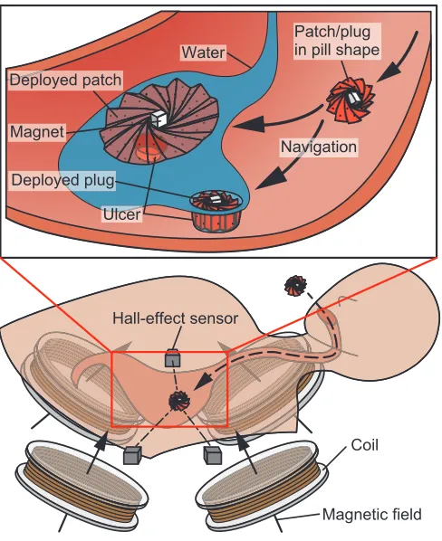
Fig. 1. The use scenario of programmable patch and plug. The patient, who has an ulcer in the stomach, ingests the origami structure folded into its pill form. After the pill reaches the stomach, it is remotely navigated to the location of ulcer by an external magnetic field. Once in place, the patient drinks water, which causes an instant deployment of the structure, reconfiguring it into a patch or plug. The structure is held in position by the magnetic field during and after deployment.
diagnose various gastrointestinal diseases [8]–[11]. Some models focus on the release of medicine [12], [13]. Some de-vices feature reconfigurability [14]–[16] and conduct various tasks such as becoming a stent [17], or feature functionality such as carrying out biopsies or releasing drugs [18]–[20].
Most of the patches/sealants are currently used for surgical purposes and must therefore be both simple to use and reliable.
This study aims to develop a “programmable pill” that a patient with perforated gastric ulcers and general gas-trointestinal lesions can simply swallow, especially in an emergency situation, which aids in the healing of the affected area (Fig. 1). This pill has an embedded magnet at the center, which allows it to be guided through the stomach towards the ulcer site using an external magnetic field. Once at the site, the structure deploys, patching or plugging the ulcer. In our previous work, we developed a bio-degradable origami device that can remove a foreign obstacle such as a button battery and also act as a patch and release a drug to treat an ulcer in the stomach [27]. This work further develops the device [28], [29], and describes a newly designed biodegrad-able, instantly water activated, highly deployable origami structure for ulcer treatment in the stomach. While there exist some approaches to patches that focus on chemically-activated bonding to the tissue [22]–[24], in this work the structure realizes a mechanical contact to the wounded site through either an expansion to fill and plug a wound, or a patch being held in place using a constant magnetic field. The structure can expand its surface area to 10 times its initial size by absorbing water, typically within a minute. The robot can be autonomously navigated to the wound site and can deploy as a patch or deploy as a plug to fill a hollow wound. The navigation was developed based on our previous work in [30], but with fewer sensors, in that three 3-axis hall-effect sensors detect the 3D position and orientation of a magnet using a localization method.
The contributions of this paper are:
1) Development of an autonomous, ingestible, deployable patch and plug for gastric ulcer treatment.
2) Method of realizing the quick and expanding agarose hydrogel sheet by hydration.
3) Geometric analysis of origami sheet deployment with a mathematical model.
4) Demonstration of 3D localization, automatic control, deployment, and patching and plugging in sequence. In the following sections, we first explain the methods of origami structure design and fabrication (Sec II), followed by 3D localization method for navigation (Sec III), then we show experimental results (Sec IV), we discuss and conclude the study (Sec V).
II. METHODS A. Deployable Origami Patch/Plug Design
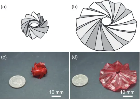
The deployment of the origami structure relies on the shape memory properties of dried agarose hydrogel. When dried in a particular shape, an structure made of agarose can be deformed to any new shape, and will return to its original shape when placed in water. We take advantage of this property by drying our structure in the unfolded origami shape, then folding it up into its smaller form when dry. Fig. 2 shows the origami structure in both its folded and
(a) (b)
(c) (d)
10 mm 10 mm
Fig. 2. The deployable origami structure. (a),(c) Folded “pill” state, (b),(d) deployed state.
deployed forms. For this study, the origami structures were made to be5cm in diameter when it fully deployed, but the design could easily be scaled to work with different sized structures depending on the task requirement.
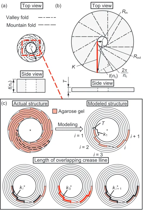
Fig. 3 (a) and (b) show the folded and fully deployed forms of the origami structure from both the top and side view. We explain the design principle for optimizing the expansion rate and targeted thickness using the following variables and constant values:
• nc≧6[-]: Number of folding creases; must be at least 6 to make a hole in the center of the origami structure • rout(nc)[mm]: Outer radius in the folded state • rin(nc)[mm]: Inner radius in the folded state • Rout (= 25mm): Outer radius in the deployed state • Rin (= 2.5mm): Inner radius in the deployed state;
radius of a hole provided at center of origami structure
• t(nc)[mm]: Thickness of origami structure in the folded state
• T (= 0.2 mm): Thickness of origami structure in the deployed state (thickness of agarose patch)
• s(nc)[mm2]: Area of the origami structure in the folded state
• S [mm]: Area of the origami structure in the deployed state
• v(nc) [mm3]: Volume of the origami structure in the folded state
• i[-]: Number of overlapping sections of agarose
• ki [mm]: Length of overlapping crease line
• K [mm]: Length of crease line in the deployed state The thickness of the origami structure at the folded state can be geometrically defined from Fig. 3 (a) and (b) as:
t(nc)∼
q
Rout2−R2 insin
2 π nc
. (1)
[image:3.612.314.558.54.227.2](a) (b)
(c)
Top view Top view
Side view Side view Agarose gel Modeling R R out K
t(n )
in 2 n ro T t ( n )c c c Valley fold Mountain fold k T 1
i = 2
i = 3
i + 1
i i = 1
ki k0
Length of overlapping crease lline
ki + 1
[image:4.612.54.301.51.413.2]Actual structure Modeled structure
Fig. 3. Schematics of the origami structure. (a) Folded state. (b) Fully deployed state. (c) Schematics to determine the number of overlapping sections. Red lineKis the length of crease line at deployed state. Black
lines (ki andki+1) are the assumed length to determine the number of
overlapping sectionsi.
sections, like the left image of Fig.3 (c). To determine the number i, we modeled the overlapping sections as shown to the right image of Fig.3 (c). When the number of over lapping sections is i= 1, the length of each crease line is:
k1=2πRin
nc . (2)
When the number of over lapping sections is i = 2, the radius is larger by the thickness of the agarose patchT. The length of each crease line is then:
k2= 2πRin nc +
2π(Rin+T)
nc . (3)
If the number of overlapping sections isi, the length of each crease line is defined as:
ki =
2π nc "
Rini+T(i−1)i 2
#
. (4)
The length of the crease lines at deployed stateK must be betweenki andki+1:
ki≦K < ki+1. (5) (a) (b) 0 5 10 15 20 25 0 0.5 1.0 1.5 2.0
6 10 14 18 22 26 30 Th
ic kn e s s o f s tr u c tu re t ( n ) (m m ) A re a o f s tr u c tu re s ( n ) (cm ) 2 (-)
Number of folding creases n (-)
Area of origami structure Thickness of origami strcture
Exp a n si o n ra te S / s ( n )
Number of folding creases n (-)
6 10 14 18 22 26 30
0 10 20 30 40 50 c c c c c
Fig. 4. Geometric analysis of the origami structure. (a) Area and thickness of the structure in its folded state over the number of creases. (b) Expansion rate of the surface over the number of creases.
When the previous eq. (5) is satisfied, the number of over-lapping sections of agaroseiis defined. eq. (5) is expressed using eq. (4) to:
2π nc "
Rini+T(i−1)i 2
# ≦
q
Rout2−Rin2
<2π nc "
Rin(i+ 1) +Ti(i+ 1) 2
# .
(6)
We can get the number of overlapping sections of agarosei
by calculating eq. (6). The outer diameter of the patch in its folded staterout(n)is shown using i:
rout(nc) =Rin+T i. (7)
Thus, the area and volume of the folded structure are given by:
s(nc) =πrout2, (8)
[image:4.612.313.555.52.380.2]v(nc) =st. (9)
[image:4.612.347.556.485.548.2]the number of folding creases is increased, the area of the origami structure increases linearly. Conversely, the thickness of the folded origami structure decreases to convergence as the number of creases is increased. Fig. 4 (b) shows the expansion rate of the origami structure (from its folded state to the deployed state). The expansion rate is calculated using:
S s(nc) =
πRout2 πrout(nc)2 =
Rout
rout(nc). (10)
The vertical axis represents the expansion rate of the surface area, and the horizontal axis represents the number of folding creases. The expansion rate decreases gently as the number of folding creases is increased. Using these results, the desired folded state for an origami structure can be designed. When the origami structure has fewer creases, it is easy to fold during fabrication, however these creases will be long and narrow, so a thicker structure with a smaller area is developed. The long and narrow structure may not stand stably. Considering these results and the fabrication process, we decided to use nc=20 as our number of folding creases to develop a stable and easily fabricated origami structure.
B. Fabrication
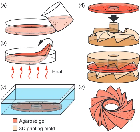
Fig. 5 shows the fabrication process of the origami struc-ture. The structure is fabricated using Melford MB1200 Agarose powder and water mixed at a ratio of 1 : 100 by mass. The solution is mixed in a beaker which is covered and placed in a larger beaker of water heated to 90◦C. Once the agarose powder has dissolved fully, the solution is poured into a container to cool and solidify Fig. 5 (a). For our
(a)
(b)
(c)
(d)
(e)
Agarose gel Heat
3D printing mold
Fig. 5. Fabrication process of the origami structure. (a) Pour liquid agarose hydrogel into a petri dish. (b) Cure in the oven for approximately5hours at 45◦C until dry, then peel off. (c) Place the patch in water for1min to re-hydrate and soften. (d) Place the patch in the mold, with the lid on, and leave to dry. (e) Once dry, fold the structure. A magnet is attached at the centre of the structure before use.
experiments, red food colouring was added before pouring the solution out. The thickness of the gel here determines the thickness of the final dried agarose which makes up the origami structure. We found that a gel thickness of approximately 4mm gives the best result for both strength and flexibility of the patch. The gel takes around10min to set. It is then placed in an oven to dry out (cure) at45◦C, for around 5 hours Fig. 5 (b). Curing the agarose outside of the mold allows the gel to dehydrate evenly with no internal mechanical stress. This unstressed, relaxed, state is that of the deployed structure. Once cured, the agarose is cut to the diameter of the 3D printed origami mold, then it is placed in water for1min to partially re-hydrate Fig. 5 (c). The agarose gel will only reabsorb a relatively small amount of water compared to what was lost in the curing stage (Pre-curing agarose sections weigh around 14g. Post curing agarose sections weigh around 0.2g. After re-hydration the agarose sections weigh around 0.8g). At this point, the softened gel is pressed into the mold and allowed to dry out once more Fig. 5 (d). This is done to form the creases along which the agarose is folded in order to package the structure for deployment. It also determines the shape that the structure will return to after deployment. The dried structure is then folded along the creases into the packaged, pleated shape. This induces locked-in strain in the folded areas Fig. 5 (e). When fully hydrated, during deployment, the structure will return to the molded shape. This is because internal strain relaxation occurs within the gel structure after re-hydration, during deployment. This strain induced ‘shape memory’ forms the basis of the structure deployment. The shape can be reprogrammed by wetting the structure and drying it again in the desired shape. The final step of the fabrication is adding the magnet. We use two cubic neodymium magnets oriented perpendicularly to the surface of the agarose to pinch the structure from either side, avoiding the need for an adhesive.
III. LOCALIZATION ANDNAVIGATION A. Electromagnetic Coil Platform
We use the coil system to control a magnet embedded within the origami structure, autonomously guiding it to the target area before deployment. The control system consists of four pairs of coaxial electromagnetic coils, with each pair consisting of one larger and one smaller coil. These coils are set up below the operating stage at an angle of π4
[image:5.612.53.298.441.673.2]Fig. 6. Schematics of 3D magnetic localization. (a) Angled view. (b) Top view.
the structure reaches the targeted location (see Sec III-B). Currents running in the coils are controlled using an Arduino DUE microcontroller, along with four motor-drivers (Syren 50, Dimension Engineering) which communicate via serial.
B. Localization and Navigation
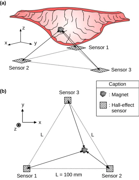
For the navigation of the pill, we developed a magnetically achievable localization system that utilized only three hall-effect sensors. The hall-hall-effect sensors (Freescale MAG3110, a small 3-axis PCB mounted magnetometer able to measure fields of±1000µT with a sensitivity of0.10µT) are placed at the vertices of a100mm edged equilateral triangle (Fig. 6). The position of the magnet is detected by trilateration with the readings from the sensors. The sensors are connected to the Arduino DUE, communicating via the I2C protocol. Since the sensors have the same fixed I2C address (0x0E) and the Arduino DUE has only one set of I2C pins (SDA and SCL), an I2C multiplexer is incorporated to allow multiple sensors to be used. The magnetic field densityB~(~r)
measured by a hall-effect sensor at location ~r with respect to the sensor location is:
~
B(~r) = µ0 4π
3( ~ m·~r)~r
k~rk5 − ~ m
k~rk3
, (11)
wherem~ is the magnetic moment of the magnet and µ0 is the permeability of free space.
Localization of the magnet is achieved by first taking a reading from one sensor. This value corresponds to the distance of the magnet from the sensor and can be used as the radius for a sphere, centred on the sensor, on which the magnet must lie. The measurement is repeated for the other two sensors, giving us three spheres which we can use to calculate the magnet position by trilateration. To do this we must find the intersection points(x, y, z)of the three spheres. Referring to Fig. 6, and assuming Sensor1is at the origin of the Cartesian space, we can derive the equations of the three spheres. We know that Sensor 1 is positioned at (0,0,0), Sensor 2 at(0, l,0), and Sensor 3 at (2l, √3l
2 , 0), so we get:
Sphere1:r2 1=x
2+y2+z2,
Sphere2:r2
2= (x−l)
2+y2+z2,
Sphere3:r2 3=
x− l
2 2
+y−√3l
2 2
+z2 ,
(12)
wherern is the distance of the magnet from sensor n and thus the radius of spheren. We use (11) - (13) to find the intersections of the three spheres, which are:
r2
1=x 2+
y2+ z2 r2
2= (x−l) 2+
y2+ z2 r2
3= (x−
l
2) 2+ (
y−√3l
2 ) 2+
z2
(13)
Resolving to get the position (x, y, z) of the magnet:
x=r21−r22+l2
2l ,
y= 1
√
3l(l
2
−xl−r2 3+r
2 1), z=±p
r2
1−y2−x2.
(14)
This gives us2 solutions: one where z is positive and one wherez is negative. We use the positive solution since we ensure that the origami structure is always above the sensors. To convert the values from the sensors to distances in millimeters, we took measurements at set distances from the magnet (every 5mm between 0 and 150mm). We ap-proximated the equation for the distance from the sensor by adding a power-type trend line. This way, we can determine the distanced of the magnet from a sensors as a function of the norm of the sensor values on each axis:
norms= p
x2
s+y2s+zs2. (15)
The three sensors have similar equations, which can be averaged as:
d(norms) = 380·norm−0 .385
s . (16)
Testing of the localization system using a magnet placed at various points on a10cm diameter circle centered on the midpoint of the three sensors determined that the average position error for the system is3.6mm.
C. Anchoring
place. The magnetic flux density applied is 5mT, which is strong enough to anchor the pill to the ulcer when water is poured over it. This anchoring field is automatically enabled once the pill reaches the ulcer.
IV. EXPERIMENTAL RESULTS A. Path Following
Fig. 7 shows the experimental results of the trajectories obtained with a cubic magnet with a rolling motion (shown in blue lines) and the targeted circular trajectories (shown in red, diameters are8cm and10cm). The magnet was placed on a flat surface and was able to follow a circular path accurately enough for our purpose. The movement of the magnet was recorded using Tracker software to compare the actual trajectory of the magnet to the desired one.
Fig. 7. Targeted paths (red) and experimentally measured magnet trajec-tories (blue; the magnet travelled along the circular path twice for each experiment). Path diameters are8cm and10cm.
In order to autonomously guide the pill to an ulcer, we first need to know the position of both the pill and the ulcer. Our localization system gives us the position of the pill, and the ulcer can be located using ultrasound or a similar medical imaging technique. Once the positions are known, a path for the pill can be planned. In our experiment on a 2D surface, the path is set straight. The pill then rolls in the direction of the ulcer, stopping after each full rotation (by turning off the coils) for2.5s to obtain sensor readings for localization without any magnetic interference from the coils. Once located, the path of the pill is recalculated.
B. Patch Deployment
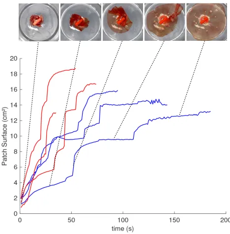
[image:7.612.317.551.55.293.2]The deployment speeds of the origami structure were measured by pouring water at room temperature (20◦C) and at body temperature (37◦C) onto the pill. The results, plotted in Fig. 8, show that an increase in temperature has the effect of speeding up the deployment process of the structure. These plots were traced with a Matlab script which detects
Fig. 8. Origami structure diameter against time during deployment. Temperature has a significant effect on the time taken for the structure to deploy. Red line is with37◦C water and blue line is with20◦C water.
the surface area of the patch. It should be noted that the initial and final surface areas stay similar for the two cases. For both, the area expanded to about10times its initial size.
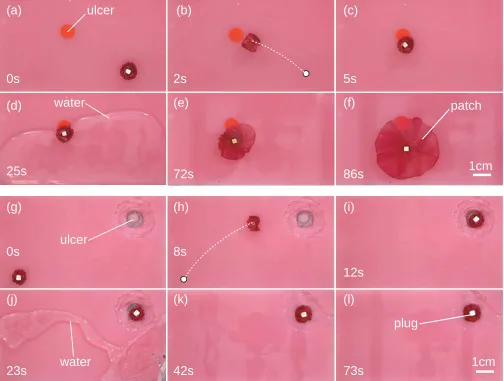
C. Entire Demonstration
Fig. 9 (a)-(f) shows the entire experiment from ingestion to the ulcer being patched by the origami structure. Fig. 9 (g)-(l) shows the same process but with the origami structure acting as a plug to fill an ulcer. For the substrate, Ecoflex 00-50 was used to represent the stomach surface, with a small sticker marking the location of the ulcer to be patched, and a 1.7cm diameter hole representing the ulcer to be plugged. The process started with the pill configuration (Fig. 9 (a)). The structure was autonomously navigated to the desired location by the system sensing the pill location magnetically, and producing a rotating magnetic field to provide the required locomotion (Fig. 9 (b),(c)). Once the targeted location was reached, the applied magnetic field was changed to a constant strong vertical magnetic field to fix the structure in place. Body temperature water (37◦C) was then poured over to initiate deployment (Fig. 9 (d)). The structure deployed to a patch, covering the ulcer area (Fig. 9 (e),(f)). The task was completed in approximately90 sec, in which
50sec was spent for full deployment. Similarly, the structure could plug a hole (Fig. 9 (g)-(l)). The process completed in approximately 80sec. The demonstrations display effective navigation and patching/plugging.
V. CONCLUSION
[image:7.612.58.292.257.453.2]Fig. 9. Entire demonstration of the autonomous patch (a)-(f) and plug (g)-(l). (a),(g) The folded structure is placed on the surface (Ecoflex 00-50), and (b), (h) autonomously navigates to the desired location. (c),(i) Once the structure is in position, a magnetic field is applied to hold it in place. (d)-(e), (j)-(k) Warm water (37◦C) is poured over to initiate the deployment of the structure, and (f),(l) within 50 sec the structure is fully deployed, plugging or patching the ulcer. We obtained a high success rate for autonomous navigation, and a reasonable rate of beyond 50% for the deployment of the structure, as in some cases the deployment causes the centre of the structure to move. This can be seen between (d) and (e), where the magnet at the centre moves positions.
autonomously navigated to the target location through a controllable magnetic field. By drinking and supplying water, the structure, which is made of agarose, swells and can be de-ployed while it is held in place by a constant magnetic field. Due to the origami-inspired design, the structure spreads to
10times its original size in the horizontal direction, enabling the size of the structure in its pill form to be small. While the patch in this study is designed to be able to fit inside a size 000 pill (the largest available pill size for human consumption), to expand and cover an ulcer with an assumed size of5cm, the result in Fig. 3 implies the pill size 00 would be sufficient for a smaller patch of 3cm diameter. We also intend to combine mechanical and chemical bonding to the tissue, taking advantage of the currently available adhesives. Adhesive patches that adhere to the human skin and organs have been developed for surgical treatment, drug delivery and monitoring the human body.
ACKNOWLEDGMENT
We thank Julien Delmas and Mark Hough for their support in developing the coil system.
REFERENCES
[1] L. Yan, T. Wang, D. Liu, J. Peng, Z. Jiao, and C.-Y. Chen, “Capsule robot for obesity treatment with wireless powering and communica-tion,”IEEE Transactions on Industrial Electronics, vol. 62, no. 2, pp. 1125–1133, 2015.
[2] J. Li, B. E.-F. de ´Avila, W. Gao, L. Zhang, and J. Wang, “Mi-cro/nanorobots for biomedicine: Delivery, surgery, sensing, and de-txification,”Science Robotics, vol. 2, p. eaam6431, 2017.
[3] C. Bergeles and G.-Z. Yang, “From passive tool holders to microsur-geons: Safer, smaller, smarter surgical robots,”IEEE Transactions on Biomedical Engineering, vol. 61, no. 5, pp. 1565–1576, 2014. [4] B. J. Nelson, I. K. Kaliakatsos, and J. J. Abbott, “Microrobots for
[5] S. Hauert and S. N. Bhatia, “Mechanism of cooperation in cancer nanomedicine: towards systems nanotechnology,” Trends in Biotech-nology, vol. 32, pp. 448–455, 2014.
[6] M. P. Kummer, J. J. Abbott, B. E. Kratochvil, R. Borer, A. Sengul, and B. J. Nelson, “Octomag: An electromagnetic system for 5-dof wireless micromanipulation,” in IEEE International Conference on Robotics and Automation (ICRA), 2010, pp. 1006–1017.
[7] D. D. Damian, K. Price, S. Arabagi, I. Berra, Z. Machaidze, S. Manjila, S. Shimada, A. Fabozzo, G. Arnal, D. Van Story,et al., “In vivo tissue regeneration with robotic implants,”Science Robotics, vol. 3, no. 14, p. eaaq0018, 2018.
[8] M. Nokata, S. Kitamura, T. Nakagi, T. Inubushi, and S. Morikawa, “Capsule type medical robot with magnetic drive in abdominal cavity,” in IEEE RAS & EMBS International Conference on Biomedical Robotics and Biomechatronics (BioRob), 2008, pp. 348–353. [9] P. Glass, E. Cheung, and M. Sitti, “A legged anchoring mechanism
for capsule endoscopes using micropatterned adhesives,”IEEE Trans-actions on Biomedical Engineering, vol. 55, no. 12, pp. 2759–2767, 2008.
[10] F. Carpi and C. Pappone, “Magnetic maneuvering of endoscopic capsule by means of a robotic navigation system,”IEEE Transactions on Biomedical Engineering, vol. 56, no. 5, pp. 1482–1490, 2009. [11] P. Valdastri, M. Simi, and R. J. Webster III, “Advanced technologies
for gastrointestinal endoscopy,” Annual Review of Biomedical Engi-neering, vol. 14, pp. 397–429, 2012.
[12] G.-S. Lien, , C.-W. Liu, J.-A. Jiang, C.-L. Chuang, and M.-T. Teng, “Magnetic control system targeted for capsule endoscopic operations in the stomach - design, fabrication, and in vitro and ex vivo evalua-tions,”IEEE Transactions on Biomedical Engineering, vol. 59, no. 7, pp. 2068–2079, 2012.
[13] I. D. Falco, G. Tortora, P. Dario, and A. Menciassi, “An integrated system for wireless capsule endoscopy in a liquid-distended stomach,” IEEE Transactions on Biomedical Engineering, vol. 61, no. 3, pp. 794–804, 2014.
[14] Z. Nagy, R. Oung, J. J. Abbott, and B. J. Nelson, “Experimental inves-tigation of magnetic self-assembly for swallowable modular robots,” in IEEE/RSJ International Conference on Intelligent Robots and Systems (IROS), 2008, pp. 1915–1920.
[15] S. Fusco, H.-W. Huang, K. E. Peyer, C. Peters, M. Haberli, AndreUl-bers, A. Spyrogianni, E. Pellicer, J. Sort, S. E. Pratsinis, B. J. Nelson, M. S. Sakar, and S. Pane, “Shape-switching microrobots for medical applications: The influence of shape in drug delivery and locomotion,” ACS Applied Materials and Interfaces, vol. 7, pp. 6803–6811, 2015. [16] H.-W. Huang, M. S. Sakar, A. J. Petruska, S. Pan´e, and B. J. Nelson,
“Soft micromachines with programmable motility and morphology,” Nature Communications, vol. 7, p. 12263, 2016.
[17] K. Kuribayashi, K. Tsuchiya, Z. You, D. Tomus, M. Umemoto, T. Ito, and M. Sasaki, “Self-deployable origami stent grafts as a biomedical application of Ni-rich TiNi shape memory alloy foil,” Materials Science and Engineering A, vol. 419, pp. 131–137, 2006.
[18] S. Yim, K. Goyal, and M. Sitti, “Magnetically actuated soft capsule with the multimodal drug release function,”IEEE/ASME Transactions on Mechatronics, vol. 18, no. 4, pp. 1413–1418, 2013.
[19] C. Lee, H. Choi, G. Go, S. Jeong, S. Y. Ko, J.-O. Park, and S. Park, “Active locomotive intestinal capsule endoscope (alice) system: A prospective feasibility study,” IEEE/ASME Transactions on Mecha-tronics, vol. 20, no. 5, pp. 2067–2074, 2015.
[20] A. M. Bellinger, M. Jafari, T. M. Grant, S. Zhang, H. C. Slater, E. A. Wenger, S. Mo, Y.-A. L. Lee, H. Mazdiyasni, L. Kogan, R. Barman, C. Cleveland, L. Booth, T. Bensel, D. Minahan, H. M. Hurowitz, T. Tai, J. Daily, B. Nikolic, L. Wood, P. A. Eckhoff, R. Langer, and G. Traverso, “Oral, ultralong-lasting drug delivery: Application toward malaria elimination goals,”Science, vol. 8, p. 365ra157, 2016. [21] J. O. Nieto, J. V. Surez, ngela Paola, and R. Gonzlez, “Utility of fibrin
glue in therapeutic endoscopy,”Rev Col Gastroenterol, vol. 24, no. 3, pp. 299–30, 2009.
[22] N. Lang, M. J. Pereira, Y. Lee, I. Friehsand, N. V. Vasilyev, E. N. Feinsand, K. Ablasser, E. D. OCearbhaill, C. Xu2, A. Fabozzoand, R. Padera, S. Wasserman, F. Freudenthal, L. S. Ferreira, R. Langer, J. M. Karp, and P. J. del Nido, “A blood-resistant surgical glue for minimally invasive repair of vessels and heart defects,”Science Translational Medicine, vol. 6, p. 218ra6, 2014.
[23] A. Assmann, A. Vegh, M. Ghasemi-Rad, S. Bagherifard, G. Cheng, E. S. Sanii, G. U. Ruiz-Esparza, I. Noshadi, A. D.Lassaletta, S. Gan-gadharan, A. Tamayol, AliKhademhosseini, and N. Annabi, “A highly adhesive and naturally derived sealant,” Biomaterials, vol. 140, pp. 115–127, 2017.
[24] J. Li, A. D. Celiz, J. Yang, Q. Yang, I. Wamala, W. Whyte, B. R. Seo, N. V. Vasilyev, J. J. Vlassak, Z. Suo, and D. J. Mooney, “Tough adhesives for diverse wet surfaces,”Science, vol. 357, pp. 378–381, 2017.
[25] N. Annabi, A. Tamayol, S. R. Shin, A. M. Ghaemmaghami, N. A. Peppas, and A. Khademhosseini, “Surgical materials: Current chal-lenges and nano-enabled solutions,”Advanced Healthcare Materials, vol. 9, pp. 574–589, 2014.
[26] E. T. Roche, A. Fabozzo, Y. Lee, P. Polygerinos, I. Friehs, L. Schuster, W. Whyte, A. M. C. Berazaluce, A. Bueno, N. Lang, M. J. N. Pereira, E. Feins, S. Wasserman, E. D. OCearbhaill, N. V. Vasilyev, D. J. Mooney, J. M. Karp, P. J. del Nido, and C. J. Walsh, “A light-reflecting balloon catheter for atraumatic tissue defect repair,”Science Transitional Medicine, vol. 7, p. 306ra146, 2014.
[27] S. Miyashita, S. Guitron, K. Yoshida, S. Li, D. D. Damian, and D. Rus, “Ingestible, controllable, and degradable origami robot for patching stomach wounds,” inICRA, 2016, pp. 909–916.
[28] S. Miyashita, S. Guitron, M. Ludersdorfer, C. Sung, and D. Rus, “An untethered miniature origami robot that self-folds, walks, swims, and degrades,” in IEEE International Conference on Robotics and Automation (ICRA), Seattle, USA, June 2015, pp. 1490–1496. [29] S. Miyashita, S. Guitron, S. Li, and D. Rus, “Robotic
metamorpho-sis by origami exoskeletons,” Science Robotics, vol. 2, no. 10, p. eaao4369, 2017.