FACULTY OF ELECTRICAL ENGINEERING
FINAL YEAR PROJECT REPORT
A RECONFIGURABLE LOGIC CONTROL METHOD FOR CIM SYSTEM
“I hereby declare that I have read through this report entitle A Reconfigurable Logic Control Method for CIM System and found that it has comply the partial fulfilment for awarding the degree of Bachelor of Mechatronic Engineering”
Signature : …..………
Supervisor’s Name: ……….……….
HATIM YASEER BIN ABDUL RAHIM
A report submitted in partial fulfilment of the requirements for the degree of Mechatronic Engineering
Faculty of Electrical Engineering
UNIVERSITI TEKNIKAL MALAYSIA MELAKA
I declare that this report entitles A Reconfigurable Logic Control Method for CIM System is the result of my own research except as cited in the references. The report has not been accepted for any degree and is not concurrently submitted in candidature of any other degree.
Signature : …..………
Name : ……….……….
ACKNOWLEDGEMENT
In the name of Allah, the most benevolent and the most merciful, I wish to record immeasurable gratitude to the One and the Almighty Creator of the universe, Allah S.W.T. It is only through His mercy and help, that this Final Year Project could be completed. Firstly, I would like to give some gratitude and appreciation to all the lecturers in Mechatronic department in FKE that has been committed for the teaching and give a lot of knowledge, guidance and moral support for around this four years of period in my learning in UTeM.
Besides that, I would like to give my appreciation and a lot of thanks to my supervisor in this project, Dr. Saifulza Bin Alwi for guidance from him this progress report for the project can be done without having any problem. This is due the consistent moral support, ideas, encouragement and supports me through this level.
ABSTRACT
ABSTRAK
TABLE OF CONTENTS
CHAPTER TITLE PAGE
ACKNOWLEDGEMENT i
ABSTRACT ii
ABSTRAK iii
TABLE OF CONTENT iv
LIST OF TABLES viii
LIST OF FIGURES ix
LIST OF ABBREVIATION xi
LIST OF APPENDICES xii
1 INTRODUCTION
1.1 Introduction 1
1.2 Motivation 3
1.2 Problem Statement 4
1.3 Objectives 5
2.1 Introduction 6 2.2 Programmable Logic Controller (PLC) 7
2.3 PLC Programming Language 8
2.3.1 SFC 9
2.3.2 LD 10
2.3.3 ST 11
2.3.4 IL 12
2.4 Petri Net 13
2.4.1 Concurrency 14
2.4.2 Synchronization 14
2.4.3 Limited Resources 15
2.4.4 Sequentially 16
2.4.5 Bipartite Graph 17
2.5 Model Checking 18
2.5.1 Promela Interpreter 19
2.6 Journal Review 20
3.1 Introduction 22
3.2 Milestone and Project Planning 24
3.3 CIM Layout 24
3.3.1 Workstation 1 26
3.3.2 Workstation 2 27
3.4 Reconfigurable Logical Control 28
3.4.1 Flow Chart 28
3.4.2 Grafcet 31
3.4.3. Ladder Diagram (LD) 32
3.4.4 Transforming LD to SFC 34
3.5 Petri Net Software 35
3.5.1 Basic Software. 36
3.5.2 Properties Setting 37
3.5.3 Bipartite Graph 38
3.5.4 Software Process 39
3.6 Project and Simulation Set Up 40
4 RESULT AND DISCUSSION 4.1 Introduction
4.2 SFC Program Test Result
42 43
4.3.2.1 T Invariant 52
4.3.2.2 S Invariant 54
4.4 Verification Properties 55
4..4.1 Liveness 55
4.4.2 Safeness 57
4.4.3 Boundedness 57
5 CONCLUSION AND RECOMMENDATION
5.1 Conclusion 58
5.2 Recommendation 58
LIST OF TABLE
TABLE TITLE PAGE
2.1 Basic Feature about Structure Text 12
2.2 Basic Language Code of Instruction List 13
2.3 Comparison of Different Journal Related 22
3.1 Planning Activities 25
FIGURE TITLE PAGE
1.1 A general layout of the CIM system 2
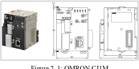
2.1 OMRON CJ1M 8
2.2 Sequential Functional Chart Diagram 10
2.3 Ladder diagram programming 11
2.4 Petri nets graphical structure 14
2.5 Modelling two parallel activities 15
2.6 Synchronization Modelling 15
2.7 Block diagram and Petri nets of a buffer with finite size 16 2.8 The producer/consumer problem with unbounded buffer 17
2.9 Petri Net structure of bipartite graph 18
2.10 Model Checking 19
2.11 Architecture of SPIN 20
3.1 Planning Process flowchart 24
3.2 Computer Integrated Manufacturing (CIM) Layout 26
3.3 Actual Souvenir Base Loader Machine 27
3.4 CAD Design Souvenir Base Loader Machine 27
3.5 Actual Engraving Machine 28
3.6 CAD Design Engraving Machine 28
3.7 Flow chart of Station 1 30
3.8 Flow chart of Station 2 31
3.9(a) GRAFCET Workstation 1 32
3.9(b) GRAFCET Workstation 2 33
3.10 Ladder Diagram Program 34
3.11(a) SFC workstation 1 35
3.11(b) SFC workstation 2 36
3.14 Installation of Initial Marking 38
3.15 Graph Workstation 1 39
3.16 Graph workstation 2 39
3.17 Software Analyzer 40
4.1(a) Result Compile Workstation 1 45
4.1(b) Result Compile Workstation 2 45
4.2 Step to Analyze Reachability 46
4.3 Software Run Test Workstation 1 47
4.4 Result of Reachability Workstation 1 48
4.5 Flow of Reachability Graph for Workstation 2 49
4.6 Software Run Test Workstation 1 50
4.7 Result of Reachability Workstation 2 50
4.8 Flow of Reachability Graph for Workstation 2 51 4.9 T-invariant of HiPS software in Workstation 1 53 4.10 T-invariant of HiPS software in Workstation 2 53 4.11 S-invariant of HiPS software in Workstation 1 54 4.12 S-invariant of HiPS software in Workstation 2(a) 54 4.13 S-invariant of HiPS software in Workstation 2(b) 55
4.14 Verification of Liveness in Workstation1 56
4.15 Verification of Liveness in Workstation2 56
LIST OF ABBREVIATION
ABBREVIATION TITLE
CIM Computer Integrated Manufacturing CAD Computer Aided Design
CAM Computer Aided Manufacturing CAAP Computer Aided Process Planning
CNC Computer Numerical Control DNC Direct Numerical Control Machine FMS Flexible Manufacturing System
ASRS Automated Storage and Retrieval System PLC Programmable Logical Controller
IEC International Electro-Technical Commission
LD Ladder Diagram
FBD Functional Block Diagram SFC Sequential Function Chart
ST Structural Text IL Instruction List
TIM Timer
IL Interlock
P Place
T Transition
I Input Process
O Output Process
LIST OF APPENDICES
APPENDX TITLE
A Drawing of Workstation B Result Turnitin
CHAPTER 1
INTRODUCTION
1.1 Introduction
Nowadays, industrial companies have to implement advance technology in order to move forward in their industry field. Thus, the Computer Integrated Manufacturing (CIM) is an example of technology that can be used as to improve all the process and the design of manufacturing process. Moreover, it also can improve the industry field to save labour cost, energy and material which it can be improve the accuracy, quality and precision of the manufacturing process.
The Computer Integrated Manufacturing (CIM) to Provide Industry with a new generation of engineers having interdisciplinary skill necessary to deal with state of the art technology in designing, manufacturing, maintenance, selecting and procuring manufacturing engineering system. CIM machine include CAD (Computer Aided Design), CAM (Computer Aided Manufacturing), CAAP (Computer Aided Process Planning), CNC (Computer Numerical Control) machine tool, DNC (Direct Numerical Control Machine Tools), FMS (Flexible Manufacturing System), ASRS (Automated Storage and Retrieval System), use of robotic and automated conveyance, computerized scheduling and production control [1].
Lin summarized the evolution of manufacturing technologies that are associated with development towards CIM system and reviewed some of the new terminologies and technologies that have been granted during the past four decades [4]. Authors also mention a close link between technical and organizational aspects like the company’s data acquisition, information about orders, production facilities, inventories and personnel which will be recorded and they form the input to the production control. This illustrates the relationship between CAM, data acquisition, production control, Computer-Aided Quality Control (CAQC) and pay-roll accounting [5]. Figure 1.1 shows a general layout of the CIM system.
Figure 1:A general layout of the CIM system [5].
As automation increasingly takes its place in industry, especially high-risk industry, it is often blamed for causing harm and increasing the chance of human error when failures occur. I propose that the problem is not the presence of automation, but rather its inappropriate design. The problem is that the operations under normal operating conditions are performed appropriately, but there is inadequate feedback and interaction with the humans who must control the overall conduct of the task. When the situations exceed the capabilities of the automatic equipment, then the inadequate feedback leads to difficulties for the human controllers [7].
PLCs are actually easier to controller than traditional hard-wired control systems. Programmable logic controllers (PLCs) have become important building blocks for automated systems. Because they have constantly increased in capability while decreasing in cost, PLCs have solidified their position as the device of choice for a wide variety of control tasks. One reason for the popularity of PLCs is their high reliability in harsh industrial environments; occasionally, however, things do go wrong and troubleshooting becomes necessary. The internal operation of a PLC can be monitored via a handheld programmer, terminal, or personal computer, and many indicator lights are provided for I/O troubleshooting. There are some limitations on what will overcome. First, it's assumed that the PLC system under analysis was operating correctly at some time in the recent past, so the problems of program debugging and wiring errors that are more typical of a start-up situation will not be addressed. It's also assumed that the PLC is programmed using some form of ladder-logic and not a higher-level language, and the discussion is limited to the most common I/O module types, namely those that support digital and analogue inputs and outputs [8].
A production machine plants consist of several operations which divided into a several workstation and at each workstation operates specific jobs or tasks that in highly automated complex system. Therefore, the operation of this plant based on the sequence of the program that being develop and also need to fulfil specification of the system. However, the errors leading defect to the product and it will lead to a highly expensive damage that need to be prevent by any necessary. Thus, to reduce this error it also needed high cost and high effort being apply to test whether to analyses the control in advance. Therefore, it can improve the reliability in the system performance by avoiding unnecessary error being produce by the system
Hence, an example for CIM, a Programmable Logic Controller can be used for the automation industry. This is because the PLC is a microcontroller that can act as central processor unit to control the sensor and other devices using the program which being design by the user itself. Therefore, PLC system is a very precise to be used in the packaging workstation because it can be programmed by the operation of sequence instruction. However, at the same time it also needed to maintain the quality of the product beside to reduce the time to operate the works. Thus, as the complexity of the application increases, it is very crucial to ensure the safeness, liveness and boundedness properties of the system, while to maintain the performance of the system.
1. To reconfigurable a logic control flow structure of a CIM system by using GRAFCET/SFC and Petri Net.
2. To verify model checking of multiple properties using Petri net software.
1.4 Scope of the project
The scopes for the project are:
1. A GRAFCET method which describe the various sequential operation. 2. Produce model of operations to operate workstation base on the SFC. 3. Model combination of the work station layout using Solidwork.
4. The method of Petri Net for analyze properties the control logic of the reconfigurable logic controller.
CHAPTER 2
LITERATURE REVIEW
This section reviews all information and method that will be implemented in this project. This include all the information method related about on PLC, program PLC language, verification of properties, model checking and many more that relating on the automation manufacturing project. Therefore, it will discuss briefly in term of history, definition, types and function of the system of the topic that will be present. Hence, this chapter also is an important way to be used as a guideline to complete this project because all the knowledge and the information from the journal and research paper are used.
2.1 Introduction
nowadays. PLC is an example of microprocessor based controller which implements programmable memory in order to do and store instructions to control the process of machine. Many industry platforms were being used such as in petro-chemical plants, smelting furnace, automobile production line and much more.
The PLC is used to apply in entirely in real-time systems. The PLC are function to control the systems by using actor and sensor [10]. For example, a sensor will act whether the tank is full or not. If the tank is full occupied, the signal from sensor will on, otherwise it will turn off. For actor the example is used to control opening and closing a valve. This condition happens when the valve is open, the tank will be filled. Therefore, the PLC will control the input signal from sensor and control the actor of the system.
[image:24.595.184.427.462.584.2]The advantage of the PLC is on the flexibility on their working. Thus, the program can be modified easily and quickly according to situation involved. As for the disadvantages of PLC, there is certain delay between the change in input and output signals.
Figure 2. 1: OMRON CJ1M
![Figure 1: A general layout of the CIM system [5].](https://thumb-us.123doks.com/thumbv2/123dok_us/74352.7008/19.595.134.478.312.624/figure-general-layout-cim.webp)