UNIVERSITI TEKNIKAL MALAYSIA MELAKA
DEVELOPMENT OF PORTABLE AIR COMPRESSOR BY
USING A BATTERY
This report is submitted in accordance with the requirement of Universiti Teknikal Malaysia Melaka (UTeM) for the Bachelor of Electrical Engineering Technology
(Industrial Power) with Honours.
by
MOHD NURALIM BIN AMZAH B071310875
910308-14-5795
DECLARATION
I hereby, declared this report entitled “Development of Portable Air Compressor by Using a Battery” is the results of my own research except as cited in references.
Signature : ………..
Author’s Name : MOHD NURALIM BIN AMZAH
APPROVAL
This report is submitted to the Faculty of Engineering Technology of UTeM as a partial fulfillment of the requirements for the degree of Bachelor of Electrical Engineering Technology (Industrial Power) with Honours. The member of the supervisory is as follow:
i
ABSTRAK
Di zaman ini, industri pengeluar kenderaan sedang membangunkan hari demi hari. Dimana sahaja kita dapat melihat kenderaan bergerak. Kenderaan akan bergerak jika tayar diisi dengan angin yang mencukupi. Kebanyakkan pemampat angin untuk mengepam tayar adalah dalam saiz yang besar dan kebanyakannya memerlukan tenaga besar iaitu AC dan susah untuk bawa kemana sahaja. Dengan masalah ini, kita boleh mengatakan bahawa terdapat keperluan pemampat udara yang mudah yang sepatutnya menjadi daya hidup produktif iaitu dalam saiz yang kecil dan juga dengan tenaga yang serba boleh (DC). Selain itu di sini dicadangkan satu garis rangka kerja yang akan memberi tenaga (DC) dan akan mempunyai keupayaan untuk terus berfungsi pada alat, sebagai contoh, bateri. Pemampat udara mudah alih menggabungkan kotak dan unit pemampat sesuai dalam projek ini. Unit pemampat menggabungkan sarung utama, omboh dipasang dengan badan silinder, motor dan komponen penghantaran. Motor tersebut memacu instrumen penghantaran untuk menggerakkan badan silinder untuk mewujudkan udara. Lubang keluar bergabung dengan ruang masuk daripadanya diperbuat daripada logam dan dirangka pada silinder. Tekanan angin dalam logam silinder akan keluar melalui lubang yang telah ada. Pam udara mudah alih ini menggabungkan semua alat penghantaran yang digunakan didalam satu tempat.
ii
ABSTRACT
In today's period, vehicles industry is developing day by day. There is not a solitary spot where you can't get the chance to see autos. The Automobiles keep running on the tires that are filled with the packed air. Till in this way, the framework that gives packed air is extremely gigantic in size, devours substantial measure of power (AC) and is not achievable to convey with. Considering these viewpoints, we can say that there is an extraordinary need of an air compressor that ought to be vitality productive (DC), little in size what's more, versatile to convey with. Subsequently here we propose an outline of a framework that will give the ideal compacted air by using least measure of force (DC) and will have the capacity to keep running on gadget, for example, batteries. A portable air compressor incorporates a box and a compressor unit suited in the case. The compressor unit incorporates a primary casing, a piston fitted with cylinder body, a motor and a transmission component. The motor drives the transmission instrument to have the cylinder body conduct responding movement in the barrel to create packed air. The barrel characterizes a way out gap speaking with an inward space thereof. A metal seat is vitally framed at the piston cylinder. The focal gap of the metal seat speaks with the way out gap of the piston cylinder. The air pump apparatus incorporates a force gadget and a transmission gadget associated together through the interfacing piece.
iii
DEDICATION
To my beloved parents,
Mr. Amzah and Mdm. Siti Saedah,
Who was raised me,
Feed me,
Accompany me,
Cheer me,
iv
ACKNOWLEDGEMENT
v
TABLE OF CONTENT
Abstrak i
Abstract ii
Dedication iii
Acknowledgement iv
Table of Content v-vi
List of Tables vii
List of Figures viii- ix
CHAPTER 1: INTRODUCTION
1.0 Background 1
1.1 Problem Statement 3
1.2 Objectives 4
1.3 Scope 4
CHAPTER 2: LITERATURE REVIEW 5
2.0 Introduction 5
2.1 Hardware Background 6
2.1.1 DC Motor 6
2.1.2 Type of DC Motor 7
2.2.2.1 Brushed Motor 7
2.2.2.2 Brushless Motor 8
2.1.3 Battery 9
2.2.3.1 Lead-Acid Battery 9
2.1.4 Piston Cylinder Type 12
2.1.4.1 Function of Cylinder Type of Piston 13
2.1.5 Pressure Gauge 14
2.1.5.1 Bourdon Pressure Gauge and the Function 15
2.2 Previous Project 16
vi
2.2.3 Concept 3: Portable Tire Inflator and Reflective Device 20
2.3 Conclusion 22
CHAPTER 3: METHODOLOGY 23
3.0 Introduction 23
3.1 Project Planning 23 3.2 Diagram of Overall System 26
3.3 Hardware Design and Sketch 27
3.4 Hardware Development 30
3.4.1 DC Motor 31
3.4.2 Lead-Acid Battery 12V 32
3.4.3 Cylinder Type of Piston 34 3.4.4 Gear 34
3.4.5 Pressure Gauge 33
3.5 Component Selection 35
3.5.1 Battery supply selection 36 3.5.2 Pressure gauge selection 37 3.6 Conclusion 38
CHAPTER 4: RESULT & DISCUSSION 39 4.0 Introduction 39
4.1 Result 39
4.1.1 The Ability of DC Motor in this project 41 4.1.2 Digital Pressure Sensor 46 4.2 Analysis Problem 49 4.3 Result Hardware, Characteristic and Conclusion 50 CHAPTER 5: CONCLUSION & FEATURE 52 5.0 Introduction 52
5.1 Recommendations 52
5.2 Conclusion 53
vii
LIST OF TABLES
3.1a 3.1b 3.2 3.3 3.4 4.1 4.2
Standard Operating Condition (RS-550 Motor) Electrical Characteristic of DC Motor
Specification Table for MSB Sealed Lead Battery Comparison between Batteries
Comparison of Pressure Gauge Output Voltage Characteristic
Characteristic of DC Motor for Tire Requirements
viii
LIST OF FIGURES
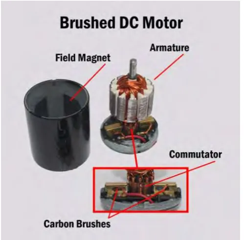
2.1 Brushed Dc Motor 7
2.2 2.3a 2.3b 2.4a 2.4b 2.5a 2.5b 2.6a 2.6b 2.7 2.8a 2.8b 2.8c 2.9a 2.9b 3.1 3.2 3.3a 3.3b 3.3c 3.3d 3.3e 3.3f 3.4 3.5 3.6 3.7 3.8 Brushless Motor
Lead-Acid Battery Separator The Design of Lead-Acid Battery Valve Detail Operation
Type of Piston Piston Inhale Piston Discharge Pressure Gauge
Pressure Gauge Construction
Portable Air Compressor (Design Concept 1) Portable Air Compressor (Design Concept 2) Tank Filling Air
Carrying Portable Air Compressor Portable Tire Inflator (Design Concept 3) Construction Triangular Portable Tire Inflator
Flowchart of Project Process Action of the Overall System Design Portable Air Compressor All equipment in one box
Design of Electrical Equipment
DC Motor that connect to the Cylinder Type of Piston The Cylinder Type of Piston
The Connecting Piece for a Pump DC Motor (RS-550 Motor)
Missile & Space Batteries (MSB) Sealed Lead Battery Type of the Piston Concept
ix 3.9 4.1a 4.1b 4.1c 4.2a 4.2b 4.2c 4.2d 4.2e 4.2f 4.2g 4.3a 4.3b 4.3c 4.3d 4.3e 4.4
The 12V 20AH Battery Supply
Circuit in Normal Condition
Circuit when switch on and motor function
Circuit when sensor have detect and cut off the supply Two picture the connection of DC Motor to a piston The input voltage while running the motor
The characteristic output that motor used
The three picture of current that increase while pump Graph Current (A) vs Air Pressure (psi)
The three picture speed (rpm) of motor taking by Tachometer The graph speed (rpm) vs Air pressure (psi)
Circuit of the Digital Pressure Sensor
Flowchart the function of Digital Pressure Sensor Pressure Sensor that use in this project
Testing the circuit
The Digital Pressure Sensor show the target Wire of Pressure Sensor is not soldering well
1
CHAPTER 1
INTRODUCTION
1.0 Background
In today's time, vehicles industry is developing day by day. The Automobiles keep running on the tires that are filled with the compacted air. Till in this way, the framework that gives compacted air is exceptionally gigantic in size, devours expansive measure of power (AC) and is not practical to convey with. Considering these viewpoints, we can say that there is an extraordinary need of an air compressor that ought to be vitality productive (DC), little in size, compact to convey with. Thus here we propose a configuration of a framework that will give the ideal compacted air by using least measure of force (DC) and will have the capacity to keep running on gadget, for example, batteries (Nerlikar et al. 2015) .
The historical backdrop of air compressor frameworks is as old as the age of the interest for packed and pressurized air. Pressurized air has been utilized as a part of numerous businesses for various applications for a long time. The requirement for compacted air came about to development of air compressor frameworks. The frameworks are without further ado mainstream in assembling and development commercial ventures where pneumatic parts are utilized to cool packed air for mechanical purposes.
2 that were controlled utilizing water wheels. This was a noteworthy stride in the historical backdrop of air compressor frameworks.
In spite of the fact that Smeaton air compressor was powerful, it was later supplanted by the impacting machine air compressor planned in 1776 by Wilkinson. This was best in class that the past adaptations and it is accepted to be the paradigm of later air compressor frameworks. It is significant that air compressors were utilized for some reasons as a part of the past days extending from, metalworking, underground ventilation, mining and creation of metals among others. Case in point, air compressor frameworks assumed an extraordinary part amid the development of the France-Italy rail framework in 1857. Later on, interest for compacted air expanded and more progressed pneumatic parts were imagined to build the generation of packed air.
As person created better approaches to utilize compacted air, interest for air compressor frameworks expanded and the innovation spread to numerous parts of the world. In the 1800, man was utilizing air compressors for vitality transmission. Engineer Viktor made an exceptionally positive move after he outlined an air compressor in Paris that delivered 18000Kw. This was trailed by various advancements in the mid twentieth century, and more enhanced pneumatic segments were similarly intended to meet the expanding requests for air compressor frameworks (Rubanova 1982) .
3 1.1 Problem Statement
Now, each and every field is in influence with the technological advancements. We cannot find a single field without technological aspects. Among all innovations, revolution in the field of automobiles has made our life exciting and easier (Nerlikar et al. 2015) .
Today car industry is at its top. Tremendous measure of improvement has been done till so far to support the business requests. Consistently we see various vehicles running all over. For a human, vehicles assume an imperative part. Car vehicles constitute a few sections that run productively.
Wheels are the base for a vehicle. Wheels are the running base of the automobiles. These wheels include tires that are loaded with the packed air. All around we get the opportunity to see compacted air filling focuses. It might be at the carport then again might be close to the petrol/diesel or gas filling stations. Today, the way packed air is picked up is excessively dreary and complex system. Each time there is need of packed air for our vehicles, we have to hurry to the closest air filling point, which is a migraine for us particularly at the point when time imperative matters. Regardless of the fact that we hurry to the air filling point, we may get packed air.
4
1.2 Objectives
i. To find the alternative to the conventional way of pumping the tire.
ii. To build a low power air compressor that use battery as a power source to made it portable.
iii. To show the air compressor pump functioning correctly when using the battery.
1.3 Scope
5
CHAPTER 2
LITERATURE REVIEW
2.0 INTRODUCTION
This chapter reviews existing project created to get an idea about the project design, conception, specification and any information that related to improve the project. In later of this chapter, some review about air compressor that proposed to fulfill this project will also be reported. This chapter also discusses about the equipment such as DC motor, cylinder type of piston and battery. It highlights some previous case studies that are related to this project from reference books, thesis, conference papers and journal.
The portable air compressor can be made as portable tire pump. This portable pump tire is made to user get easier and comfortable when use. As we know, pump tire is use manually. This system that want to make is portable and automatic compress the air into the tire. In this final project need to build a portable air compressor for tire pump and it is mean that have to develop the portable tire pump and compress the air without be controlled by human.
6 As needs be, it is a general object of the present development to give a compact pneumatic machine that conquers the simply portrayed issues by having an independent force supply that renders the pump truly versatile [6].
2.1 HARDWARE BACKGROUND
This topic discusses the equipment that want to use either electrical or the housing hardware based on what has been find with literature study.
2.1.1 DC MOTOR
The DC motor takes the electrical energy from the battery 12v and converts it to the mechanical work necessary to drive the cylinder type of piston to replace the valve to compress the air. This DC Motor is electric motor which uses direct current (DC – Direct Current). This DC Motor has two terminals only. Motor will be turning when two terminals given voltage according to the need for example 12V. The direction of the rotation of the motor depends on polarity supply. The gear must have at motor’s shaft to rotate the shaft of the piston (James et al. 2007) .
7 2.1.2 Type of DC Motor
2.1.2.1 Brushed Motor
A Brushed Motor has a turning set of wound wire curls called an armature which goes about as an electromagnet with two posts. A mechanical rotational switch called a commutator inverts the course of the electric current twice every cycle, to move through the armature so that the shafts of the electromagnet push and draw against the perpetual magnets on the outside of the motor. As the posts of the armature electromagnet pass the shafts of the changeless magnets, the commutator inverts the extremity of the armature electromagnet. Amid the moment of exchanging extremity, dormancy keeps the established engine going in the best possible heading. Figure 2.1 show the example of brushed DC motor.
[image:21.595.213.463.426.671.2]8 Despite the fact that DC brushed motor are extremely efficient and cheap, issues connected with the brushed DC motor is that starting happens under heavy load conditions between the two surfaces of the commutator and carbon brushes bringing about self-creating heat, short life range and electrical noise because of sparking.
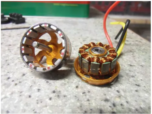
2.1.2.2 Brushless Motor
A DC Brushless Motor that show in Figure 2.2 has uses a perpetual magnet outside rotor, three periods of driving curls, one or more Hall impact gadgets to sense the position of the rotor, and the related drive hardware. The curls are enacted, one stage after the other, by the drive gadgets as prompted by the signs from the Hall impact sensors, and they go about as three-stage synchronous motor containing their own particular variable recurrence drive hardware.
Figure 2.2: Brushless Motor
[image:22.595.230.480.425.612.2]9 2.1.3 BATTERY
The battery selection is very important to relate with the system and must have the suitability with the system. A wide range of electronic equipment uses uninterruptible power system units in order to continue operating in case there is loss of power supply and the battery must available
to charge to regulate that supplies the load with DC voltage (Kokkosis et al.
2012) .
The battery is recharged following the recovery the fully charged state. Battery power, energy capacity and service life are the main factors in the design of a standby system (Wong et al. 2008) .
The first important thing to figure out what voltage the motor is going to use. The motor maybe come with specifications. The motor controllers are designed to run from 5V to 12V. The second thing to figure out is how much current of the motor will need. These criteria are very important to select the suitable battery for drive the 12v DC motor.
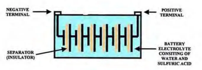
2.1.3.1 Lead-Acid Battery
10 Figure 2.3(a): Lead-Acid Battery Separator
A twelve-volt battery has six single cells in arrangement creating a completely charged output voltage of 12.6 volts. The example showed on Figure 2.3(b).
Figure 2.3(b): The design of Lead-Acid Battery
[image:24.595.210.502.71.178.2] [image:24.595.214.556.314.433.2]