i
DESIGN AND DEVELOPMENT OF A WIRELESS WATER LEVEL MEASURING AND NOTIFICATION SYSTEM
MOHD IZUDDIN BIN ZAKARIA
This report is submitted in partial fulfillment of requirement for the Bachelor Degree of Electronic Engineering (Computer Engineering)
Faculty of Electronic Engineering and Computer Engineering Universiti Teknikal Malaysia Melaka
ii
UNIVERSTI TEKNIKAL MALAYSIA MELAKA
FAKULTI KEJURUTERAAN ELEKTRONIK DAN KEJURUTERAAN KOMPUTER BORANG PENGESAHAN STATUS LAPORAN
PROJEK SARJANA MUDA II
Tajuk Projek: DESIGN AND DEVELOPMENT OF A WIRELESS MONITORING WATER LEVEL MEASURING AND NOTIFICATION SYSTEM
Sesi Pengajian: 1 6 / 1 7
Saya MOHD IZUDDIN BIN ZAKARIAmengaku membenarkan Laporan Projek Sarjana Muda ini disimpan di Perpustakaan dengan syarat-syarat kegunaan seperti berikut:
1. Laporan adalah hakmilik Universiti Teknikal Malaysia Melaka.
2. Perpustakaan dibenarkan membuat salinan untuk tujuan pengajian sahaja.
3. Perpustakaan dibenarkan membuat salinan laporan ini sebagai bahan pertukaran antara institusi pengajian tinggi.
4. Sila tandakan ( √ ) :
SULIT* *(Mengandungi maklumat yang berdarjah keselamatan atau
kepentingan Malaysia seperti yang termaktub di dalam
AKTA RAHSIA RASMI 1972)
TERHAD** **(Mengandungi maklumat terhad yang telah ditentukan oleh
organisasi/badan di mana penyelidikan dijalankan)
TIDAK TERHAD Disahkan oleh:
(TANDATANGAN PENULIS) (COP DAN TANDATANGAN PENYELIA)
iii
“I hereby declare that I have read through this report entitle ‘Design and Development of a Wireless Water Level Measuring and Notification System’ and found that it have
comply the partial fulfilment for awarding the Bachelor Degree of Electronic Engineering (Computer Engineering).”
iv
“I declare that this report entitle ‘Design and Development of a Wireless Water Level Measuring and Notification System’ is the result of my own research excerpt as cited in
the references.”
v
This thesis is dedicated to
My family for their supports
vi
ACKNOWLEDGEMENT
Bismillahirahmanirrahim.
Alhamdulillah, thanks to the almighty god ALLAH SWT, for His help and blessing for giving me this opportunity to complete my final year project entitle “Design and Development of a Wireless Water Level Measuring and Notification System”.
First and foremost, I would like to express my heartily gratitude to my supervisor, Dr. Amat Amir bin Basri for the guidance and enthusiasm given throughout the progress of this project. I am most grateful for her willingness to offer help to the very end of this project.
My appreciation also goes to my family who has been so supportive mentally and financially throughout this project and also providing me the opportunity to study in UTeM Melaka and provide support in terms of spirit and financial. I would not been able to further my studies to this level without them.
Nevertheless, my great appreciation dedicated to my friends and those whom involve directly or indirectly with this project. There is no such meaningful word than Thank You So Much.
vii
ABSTRACT
viii
ABSTRAK
ix
TABLE OF CONTENTS
CONTENTS PAGE
PROJECT TITLE ………...ii
SUPERVISOR DECLARATION………..iii
STUDENT DECLARATION……….iv
DEDICATION………..v
ACKNOWLEDGEMENT………..vi
ABSTRACT………vii
ABSTRAK……….viii
TABLE OF CONTENTS………ix
LIST OF FIGURES………...xiii
LIST OF TABLES………..xv
LIST OF ABBREVIATIONS………...xvi
CHAPTER 1: INTRODUCTION 1.1Project background………...1
1.2Objective………...2
1.3Problem statement………2
1.4Scope of project………3
1.5Report organization………..3
x
CHAPTER 2: LITERATURE REVIEW
2.1 Introduction………...5
2.2 Research background………....6
2.2.1 Sensor………6
2.2.2 Microcontroller………..8
2.2.3 Wireless communication device………...9
2.3 Analysis………..10
2.3.1 Limitation………10
2.4 Conclusion………..11
CHAPTER 3: METHODOLOGY 3.1 Introduction……….12
3.2 Project flowchart.………12
3.3 Software development………14
3.3.1 Arduino Uno compiler……….15
3.3.2 Proteus 8………...17
3.3.3 Software flowchart………...19
3.3.3.1 Arduino Uno……….20
3.3.3.2 Proteus 8………21
3.4 Hardware development………...22
3.4.1 Ultrasonic sensor………..22
3.4.2 LEDs and buzzer………..22
3.4.3 LCD display……….23
3.4.4 Microcontroller………23
xi
3.4.6 Hardware flowchart……….24
3.5 Prototype……….25
3.5.1 PCB fabrication………27
3.5.1.1 Image transfer………...28
3.5.1.2 Exposing and developing resist layer………29
3.5.1.3 Etching process……….29
3.5.1.4 Electroplating process………...30
3.5.1.5 Drilling printed circuit………...31
3.5.1.6 Soldering………...31
3.6 Conclusion………..32
CHAPTER 4: RESULT AND DISCUSSION 4.1 Introduction……….33
4.2 Block diagram...………..34
4.3 Software design………...34
4.3.1 Arduino Uno………34
4.3.2 Proteus 8………...37
4.4 Hardware design……….39
4.5 Analysis………..41
4.6 Discussion………...42
4.7 Conclusion………..42
xii 5.2 Recommendation………44
REFERENCES………...45
xiii
LIST OF FIGURES
FIGURE NO. TITLE PAGE
2.1 Ultrasonic sensor level transmitter 6 2.2 Pulse module timing diagram 7 2.3 Theoretical equation 7
2.4 Arduino Uno 8
2.5 GSM modem 9
3.1 Project flowchart 13
3.2 USB port setting 17
3.3 Component selection 18
3.4 Uploading coding to microcontroller in simulation 18
3.5 Example PCB layout 19
3.6 Coding development flowchart 20 3.7 Simulation flowchart 21 3.8 Hardware development flowchart 24 3.9 Prototype front view 26 3.10 Prototype upper view 26 3.11 Control box components 27 3.12 Project PCB layout 28
xiv 3.14 Interface circuit layout 30 3.15 Soldered interface circuit 31
4.1 Block diagram 34
4.2(a-f) Coding system 35
4.3 Simulation circuit 38
4.4 Interface circuit PCB layout 38
4.5 Start-up system 39
4.6 First condition 40
4.7 Second condition 40
4.8 Third condition 41
xv
LIST OF TABLES
TABLE NO. TITLE PAGE
xvi
LIST OF ABBREVIATIONS
ETSI European Telecommunications Standards Institute 2G Second Generation
LED Light Emitting Diode GSM Global System for Mobile CDMA Code Division Multiple Access SMS Short Message Service
USB Universal Serial Bus
SIM Subscriber Identity Module LCD Liquid Crystal Display
PIC Programmable Integrated Circuit PCB Printed circuit board
GPS Global Positioning System UV Ultraviolet
DC Direct Current
M Mega
K Kilo
Hz Hertz
V Voltage
1
CHAPTER 1
INTRODUCTION
1.1 PROJECT BACKGROUND
Wireless water level measuring system and notification system is a system to detect water level and allow user to interact with system to get the condition of water level in a container. This system required a suitable sensor to detect the surface of water to measure its distance. To perform this, a non-contact distance measurement sensor will be used to detect surface of water level. Then sensor will detect several stage of water level by using a microcontroller as control circuit.
2
The information will transfer to GSM modem for further action. From GSM modem, a sim card will use to create a wireless communication device so that it will transmit the information from control circuit via short message service (SMS). User also can send message directly to GSM modem to ask the information for water level.
1.2 OBJECTIVE
To overcome this, there were few objectives to complete:
i. To construct and study the application to monitoring water level ii. To study and analyze the ability of GSM modem
iii. To design and develop wireless notification system
1.3 PROBLEM STATEMENT
Monitoring system is not a new invention,Problem happen with current system is information cannot be transfer to user directly. So, suitable way to overcome this problem is using GSM modem. There are several type of way to connect GSM modem etc. Bluetooth and USB. But this project will use a SIM card to create a wireless communication device to connect to cell phone.
3
1.4 SCOPE OF PROJECT
The sensor will be choose by analyse several type of water sensor. This sensor need to detect water so it need to be fit with the environment because water is liquid. Suitable sensor was identified and give satisfactory result. Then, construct a control circuit to make the sensor detect 3 stage of water level. Control circuit is the main of the system and take care all of the system.
To develop this, a microcontroller is used for control circuit. Microcontroller perform using C++ language to activate the sensor. So, a microcontroller compiler will be utilized to create the program. Then build connection from control circuit to communication device to transfer the information. GSM modem will take part as a communication device.
1.5 REPORT ORGANISATION
This report is represented in 5 chapters. Chapter 1 focuses on brief introduction of the project carried. The important overview or description including problem statement, project objective and project scopes are also explained in this chapter.
In Chapter 2 is based on literature review of the project. It is mainly focused on the review of previous project that have done. Some analysis is done to identify the progression and method that has been used for the previous project.
4
In Chapter 4, the preliminary result and discussion are included in this chapter to explain the result that has been achieved after did hardware and software implementation.
In Chapter 5, the conclusion and recommendation of future work are discussed. All chapters are summarized and recommendations are given for a better result in future work.
1.6 CONCLUSION
5
CHAPTER 2
LITERATURE REVIEW
2.1 INTRODUCTION
A literature review is an evaluative report of information which related to Wireless water level measuring system and notification system. This chapter will give a detailed description about what have been published on some topics by scholars and researchers. The main purpose of writing this literature review is to gets knows knowledge and ideas that have been established about the system that focusing sensor will be used to detect the surface of water level. It also will show the strength and weakness of the system.
Besides that, there are resources on the topic of monitoring system have been widely published. The information has been collected from different resources such as published documentation, white paper and journals in the web site.
6
enhanced system such as backup and recovery, system architecture, circuit design, export and import data and the integrity within the different application.
2.2 RESEARCH BACKGROUND
2.2.1 SENSOR
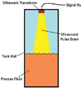
Ultrasonic sensor is non-contact measurement distance sensor. This sensor used ultrasound pulse beam to measure distance of an object. Ultrasonic sensor consists of two part that is transmitter or transducer and receiver. For this, transmitter is output that will produce ultrasound beam. Ultrasound pulse beam move in the air from transmitter to object and reflect it back to receiver [1]. Figure 2.1 show how
[image:22.595.232.401.405.589.2]ultrasonic sensor work.
Figure 2.1: Ultrasonic sensor level transmitter
7
reflect back to the receiver [2]. Figure 2.2 show the pulse module send by trig pin at
[image:23.595.127.538.142.242.2]ultrasonic sensor.
Figure 2.2: Pulse module timing diagram
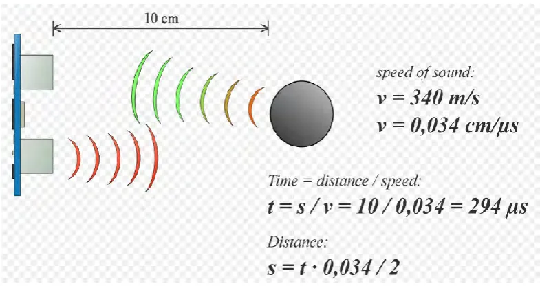
To perform ultrasonic sensor, theoretical equation must be applied in coding. The calculation for this equation is as Figure 2.3 below.
[image:23.595.122.515.413.621.2]8
Time will become the subject to perform the distance measurement for Arduino according time taken of wave form from receiver and reflect when collapse with object to receiver.
2.2.2 MICROCONTROLLER
For this approach, Arduino is open source project to interactive objects that can sense and control physical devices micro. Arduino 1st introduced in 2005 that aiming
to help user create device to interact with their environment [3]. Arduino also easy to
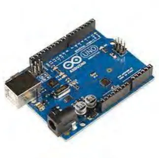
[image:24.595.239.401.387.548.2]handle by user, so it widely used for project and the language used for coding simple. Arduino used C++ language coding but it different with PIC. Figure 2.4 show the microcontroller used for this project.
Figure 2.4: Arduino Uno