www.nature.com/scientificreports
Polar Spinel-Perovskite Interfaces:
an atomistic study of Fe
3
O
4
(111)/
SrTiO
3
(111) structure and
functionality
Daniel Gilks
1, Keith P. McKenna
1, Zlatko Nedelkoski
1, Balati Kuerbanjiang
1,
Kosuke Matsuzaki
2, Tomofumi Susaki
2, Leonardo Lari
1, Demie Kepaptsoglou
3,
Quentin Ramasse
3, Steve Tear
1& Vlado K. Lazarov
1Atomic resolution scanning transmission electron microscopy and electron energy loss spectroscopy combined with ab initio electronic calculations are used to determine the structure and properties of the Fe3O4(111)/SrTiO3(111) polar interface. The interfacial structure and chemical composition are shown to be atomically sharp and of an octahedral Fe/SrO3 nature. Band alignment across the interface pins the Fermi level in the vicinity of the conduction band of SrTiO3. Density functional theory calculations
demonstrate very high spin-polarization of Fe3O4 in the interface vicinity which suggests that this
system may be an excellent candidate for spintronic applications.
Oxide heterostructures are of interest for developing new functional materials due to their rich physical proper-ties1–5. Many oxides are insulators, but oxide materials also provide wide band gap semiconductors6, superconduc-tors7, ionic conductors8, ferrimagnetic9 and antiferromagnetic10 materials. As such, oxide multilayer structures provide a broad platform for devices with multifunctional properties. The functionality of oxide devices depends strongly on the atomic scale structural and electronic discontinuities across multilayer heterostructure inter-faces; therefore we need an atomic scale understanding of their interfacial properties. In this work we focus on spinel-perovskite heterostructures that have great potential for the development of multiferroic devices by using Fe3O4/SrTiO3 as a model system11,12.
One of the main issues in semiconductor spintronics is the effective spin injection into semiconductors due to the large conductivity mismatch between the ferromagnetic film and semiconducting substrate. This can be overcome i) if the ferromagnetic electrode is 100% spin-polarised i.e. halfmetallic, ii) by tailoring the conductiv-ity of the semiconducting substrate to match that of the ferromagnetic film. Both conditions in principle can be addressed by considering the Fe3O4/SrTiO3 heterostructure due to the low conductivity and half-metallic prop-erties of Fe3O413–15 as well as tunable conductivity of SrTiO3(STO), making this structure an excellent candidate for spintronic applications.
Along the [111] direction both Fe3O4 and STO are chemically layered polar materials, hence the growth along this direction is much more challenging16 compared to the growth along the neutral [100] direction for which num-ber of studies have been reported12. STO is defined by alternating SrO
3 and Ti planes. The complex arrangement of Fe sites in the Fe3O4 spinel structure gives tetrahedral (FeA) and octahedral (FeB) sites with six unique atomic planes described by “… 4O/3FeB/4O/FeA-FeB-FeA/4O… ” along the [111] direction (Supplementary Figure S1). This leads to twelve nominal interfacial terminations between the STO substrate and the Fe3O4 film which could be exploited for the purpose of interfacial atomic engineering. The variety of possible atomic structures at the polar Fe3O4/STO(111) interface could be explored to understand the interface electronic structure effects on spin tunnelling/injection in semiconductors, a crucial phenomenon for spin injection in semiconductors that is still poorly understood. Furthermore, an additional benefit of using two oxides to form such a heterostructure is their chemical stability compared to metallic ferromagnetic/SC systems (where SC is either a III-V (e.g. GaAs) or
1Department of Physics, University of York, Heslington, York, YO10 5DD, UK. 2Secure Materials Center, Materials
and Structures Laboratory, Tokyo Institute of Technology, 4259, Nagatsuta, Midori-ku, Yokohama 226-8503, Japan.
3SuperSTEM, STFC Daresbury Laboratories, Keckwick Lane, Warrington, WA4 4AD, UK. Correspondence and
requests for materials should be addressed to V.K.L. (email: [email protected]) received: 13 April 2016
www.nature.com/scientificreports/
elemental (e.g. Si) semiconductor) whose performance often suffers through the formation of unwanted interfa-cial phases. The experimental realisation of polar oxides heterostructures is challenging, since the main obstacle is the divergent electrostatic potential of the grown film. It is well known that the bulk terminated polar metal-oxide surfaces are generally unstable; they have very high surface energy due to the large electrostatic contribution from the presence of a dipole moment in the repeat unit normal to the surface17. In a simplified picture, the ionic crystal along the polar direction can be viewed as a system of parallel opposite charged planes, thus even for polar films with small thickness the electric dipole moment is huge, and in the limit of number of layers N→∝, leads to the so-called ‘electrostatic catastrophe’. In the case of polar heterostructures the interface ‘electrostatic catastrophe’ has to be mitigated by stabilisation mechanisms such as atomic mixing, interface roughening and faceting and/or pure electronic interface reconstructions16–20. The relative chemical stability of oxide/oxide interfaces compared to ferromagnet/semiconductor interfaces21 opens the possibility of tailoring metastable interface structures with potential for device applications.
In contrast to previous studies on Fe3O4 films grown on STO12, in this work we focus on interface atomic structure determination by advanced electron microscopy methods. By employing pulsed laser deposition (PLD) growth and atomically-resolved aberration corrected scanning transmission electron microscopy (STEM) and electron energy loss spectroscopy (EELS) we demonstrate that atomically sharp polar oxide spinel (Fe3O4 )/per-ovskite (SrTiO3) junctions can be achieved experimentally. Band alignment across the Fe3O4/SrTiO3 interface calculated by Density Functional Theory (DFT) shows that the Fermi level is pinned in the vicinity of the conduc-tion band of the SrTiO3. Moreover, the spin polarisation of Fe3O4 is preserved even at the interface suggesting that this system could be an excellent candidate for spintronic applications. Finally, this work provides an example of a class of materials that can host ferromagnetic and ferroelectric properties, which can be potentially coupled by suitable interface engineering.
Fe3O4 crystalizes in the inverse spinel structure with a lattice constant of 0.834 nm and space group Fd-3m22. The oxygen sublattice forms a fully occupied FCC lattice with Fe occupying interstitial sites. The dominant super-exchange interaction in Fe3O4 between tetrahedral (FeA) and octahedral (FeB) sublattices results in their antiferromagnetic alignment23,24. Since there are twice as many Fe atoms on B sites compared to A sites this gives an overall magnetisation of 4.08 μB/formula unit. Recent interest in magnetite as a spin-polarised electrode and therefore its use within this model heterostructure stems from band structure calculations which predict 100% spin polarisation at the Fermi level, a property highly desirable for spintronic applications. In contrast, SrTiO3 is an insulating oxide (band gap 3.25 eV) with perovskite structure; however with Nb doping STO can become an effective semiconducting material and even a metallic conductor25,26. Therefore STO could be used either as a spin tunnel barrier or a medium for spin current diffusion in the insulating and semi-conducting phase respectively.
Results and Discussion
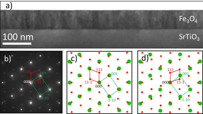
[image:2.595.158.549.46.265.2]The structural quality of Fe3O4 (111) film grown by PLD is shown in Fig. 1, with further characterization pro-vided in the Supplementary Figure S2. The film has a single crystal structure and uniform thickness. The long
www.nature.com/scientificreports/
range single crystal nature of the film and the parallel (111) planes shared between the film and substrate can be identified from the XRD θ -2θ patterns, as shown in Supplementary Figure S2. The clearly defined crystallographic orientation between the Fe3O4(111) film and STO(111) substrate was additionally confirmed by selected area electron diffraction (SAD) given in Fig. 1b. Comparison of simulated SAD patterns for a simple cube-on-cube epitaxy (Fig. 1c) and a twinned cube-on-cube epitaxial relationship (Fig. 1d) with the experimental SAD pattern (Fig. 1b) shows that the Fe3O4/STO epitaxy is determined by a twinned cube-on-cube epitaxial relation given by the following relationship: Fe3O4(111)||STO(111) and Fe3O4(−110)||STO(1−10).
A high angle annular dark field (HAADF) STEM image of the interfacial region along the [1−10] zone axis is shown in Fig. 2. The distinction between the projected atomic structures of the perovskite (substrate) and the spinel (film) is clearly observed. The HAADF image shows that the interface between the perovskite (STO) and spinel (Fe3O4) structure is atomically abrupt. Based on the HAADF intensities we can identify the positions of the atomic columns of Fe, Ti and Sr; note that in the imaging conditions used, the intensity of O atomic columns is negligible compared to that of Sr, Ti and Fe and therefore O columns cannot be clearly identified in the HAADF image. The brighter sites in the STO region are identified as the projection of mixed Sr-O atomic columns (pur-ple), while the lower intensity sites are the Ti atomic columns (green dots). In the [1−10] viewing direction octahedral and tetrahedral Fe atoms in Fe3O4 are in separate atomic columns. In order to visually distinguish the octahedral (FeB) and tetrahedral (FeA) atomic columns, the FeA sites are labelled with yellow while the FeB sites with red dots in the overlaid ball model in Fig. 2. The intensity variation between FeB sites on the ‘3FeB’ plane is due to alternating double and single occupation of the octahedral atomic sites in this projection. By following the bulk-like stacking of STO and magnetite, the interface region can be identified as the region between the white and yellow dashed lines drawn in Fig. 2 as a guide to the eye. It can be clearly seen that the atomic planes just above the white and below the yellow dashed line nominally correspond to magnetite’s ‘3FeB’ and STO’s ‘Sr-O’ atomic planes, respectively. The inset in Fig. 2 is a magnified view of the interface and reveals the atomic structure within the interface region with two distinctive atomic columns labelled as ‘a’ and ‘b’. The lower intensities of these interface atomic columns rules out the Sr-O as a plane in the interface region, suggesting that these columns are either Fe or Ti. However, based solely on the HAADF intensities the chemical nature of these atomic planes can-not be uniquely determined.
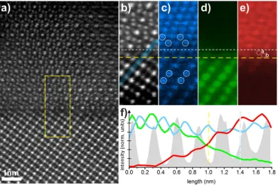
[image:3.595.157.394.44.278.2]Further insight into the chemical nature of the interface atomic columns can be provided by atomic level elemental mapping using STEM – EELS measurements (Fig. 3). One of the advantages of the technique is that it allows a simultaneous acquisition of the spectroscopic and HAADF imaging signals and therefore direct cor-relation of the image contrast with chemical information, as illustrated in Fig. 3. The HAADF survey image of the interface region used for atomically-resolved chemical mapping is shown in Fig. 3a. Elemental maps were acquired by rastering the electron probe serially across the region outlined by the yellow rectangle (Fig. 3a) and collecting an EEL spectrum at each position. Figure 3b shows the HAADF signal intensity acquired during EELS acquisition. This image forms a reference position for the atomically-resolved elemental maps shown in Fig. 3c–e.
www.nature.com/scientificreports/
Figure 3c shows that O planes between the STO and Fe3O4 are continuous. The lower intensity observed on alternate positions in the STO is due to the shared atomic columns with Sr. The twinning of the FCC stacking sequence (outlined by the open white circles) which has been also deduced from the SAD (Fig. 1b) is confirmed in this map with the twin structure occurring across a single (111) atomic plane, which we use as a reference inter-face plane (outlined with yellow dashed line which corresponds to the yellow dashed line from Fig. 2). Figure 3d shows the Ti L2,3 edge intensity map reflecting the Ti atomic columns positions in the STO. This map demon-strates that the Ti signal abruptly decreases across the interface without any considerable presence of Ti above the reference plane. This in turn excludes the presence of Ti as the predominant chemical species within the interface ‘a’ and ‘b’ atomic columns. Figure 3e shows the elemental map of iron atomic columns, obtained using the Fe L2,3 ionisation edge. While the Ti L2,3 signals disappears sharply above the reference plane the Fe L2,3 signal is clearly present just above the reference plane. By comparing this map with the simultaneously acquired HAADF image (Fig. 3b), it can be seen that the Fe signal peaks at the ‘a’ and ‘b’ structural positions, thus suggesting these corre-spond to Fe atomic sites. Based on the above analysis a unique determination of the Fe3O4/STO interface, and in particular the chemical nature of the two atomic planes located just above the interface reference plane, can be obtained. The atomic columns ‘a’ and ‘b’ are located in the structural positions of a tetrahedral FeA and octahedral FeB atomic columns, respectively; when the interface is fully relaxed. The strong Fe L2,3 signal from STEM-EELS in both ‘a’ and ‘b’ sites provides strong evidence that the interface atomic structure is defined by a FeA-FeB/SrO3 atomic stacking. It is worth noting that the structural position of the O plane (outlined with the white dashed line in Fig. 3c) is located just above the ‘a’ (i.e. tetrahedral Fe) and below the ‘3FeB’ plane, as expected for bulk-like magnetite structure.
A small amount of inter-diffusion may be also present at the interface as indicated by the EELS line pro-files in Fig. 3f taken along the Ti atomic columns as outlined in Fig. 3b. These propro-files suggest a relatively small inter-diffusion within two atomic planes (with respect to the interface reference plane) of both Fe and Ti. It should be noted however that these observations of small EELS intensity (Fig. 3f) could also arise from surface steps or channelling effects through the sample.
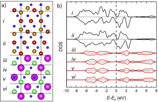
[image:4.595.160.552.46.307.2]Based on the above EELS analysis we create an atomic model (Fig. 4a) of the interface as follows: … 3FeB/4O/ FeAFeB-SrO3/Ti… This model has been structurally optimized using density functional theory (DFT). The spin-resolved layer-by-layer density of states (SDOS) across the interface are shown in Fig. 4b. Partial SDOS are calculated by projecting onto atoms within specific regions in the supercell as indicated by the labels i–vi in
Figure 3. HAADF-STEM and STEM-EELS from interfacial region. (a) Region of interest selected from HAADF-STEM imaging. (b) HAADF-STEM signal showing atomic resolution imaging produced concurrently with EELS acquisition. (c) Spatially resolved intensity of O K edge signal. Lower intensity observed on alternate positions in the substrate is due to the shared (with Sr) atomic columns: Sr-O. Open circles outline the twinning (also demonstrated by the SAD pattern) of the O sublattice across the interface. Note that the positions of the dashed yellow and white line are the same as in Fig. 2. (d) Spatially resolved intensity of Ti L2,3 signal.
www.nature.com/scientificreports/
Fig. 4a. These structural regions represent complete formula units of the respective materials, i.e. the upper black plots, (i and ii) represent Fe3O4 layers and the lower red plots (iii–vi) represent SrTiO3 layers. Aside from the two SDOS projections on either side of the interface (ii and iii) the non-interfacial projections show a rapid return to bulk-like electronic structure in both Fe3O4 and STO (Supplementary Figure S1), suggesting that the interfacial effects are confined to ~1 nm interface vicinity. By analysing the SDOS in Fig. 4b we observe that the band
align-ment across the interface puts the Fermi level within the STO band gap, close to the conduction band. This prop-erty could allow efficient spin tunnelling across a suitably thin STO barrier, as well as spin injection into STO, without significant injection of holes into Fe3O4. In addition, the SDOS show that very near the interface (~6 layers) the Fe3O4 band gap and the spin-polarisation (~90%) are only slightly reduced compared to the corre-sponding bulk values.
In summary, understanding the electronic and the atomic/chemical structure of the spinel/perovskite inter-face is an important step in creating multifunctional devices, due to the rich functional properties of materials that crystalize into these two structures. In this work on the Fe3O4(111)/STO(111) model system, we have demon-strated that atomically sharp spinel-perovksite heterojunctions are feasible. A STEM/EELS atomic study of the Fe3O4/STO interface has shown that the interface is determined by FeA-FeB/SrO3 atomic planes. This particular atomic configuration retains the negative spin polarisation of the magnetite film even at the interface, demon-strating that the experimentally realised Fe3O4(111)/STO(111) interface can be used as a platform for studying spin injection from half-metals. Hence it provides an opportunity for studying fundamental properties such as spin injections and tunneling in model devices.
Methods
Fe3O4 films have been grown on (111) oriented Nb 0.05 wt% doped SrTiO3 substrates (Shinkosha LTD) by PLD using a KrF excimer laser (λ = 248 nm) incident on a Fe3O4 target with 3N purity, with a pulse duration of 20 ns and power density of 2.3 J cm−2 cycling at 10 Hz27. Substrates have been prepared for deposition with a buffered NH4F-HF solution etch28 and a 60 minute anneal at 1050 °C in air to reduce surface roughness and remove surface contaminants. Prior to deposition the substrate condition and orientation has been checked using reflection high energy electron diffraction (RHEED). Deposition was performed with the substrate held at 300 °C by the ablation of a sintered Fe3O4 target in a background oxygen atmosphere of 2 × 10⁻⁴ Pa. In order to improve crystalline ordering as well as decrease the number of defects such as antiphase boundaries and twin defects29 we have per-formed postdeposition annealing at 1000 °C for 60 minutes in a CO2/CO gas atmosphere27. The partial pressure ratio of CO2/CO was set to 1000 which gives an effective O2 partial pressure of ~10−4 Pa. Deposited specimens have been characterised with θ -2θ X-ray Diffraction (XRD) scans to identify the reflections of Fe3O4 and STO and to ensure the growth mode has given correctly oriented, epitaxial growth.
[image:5.595.156.477.48.254.2]Cross-sectional transmission electron microscopy (TEM) specimens have been prepared by conventional methods that include mechanical thinning/polishing and finishing with low angle Ar ion milling using a cold stage equipped PIPS 691 (Gatan Inc.) to achieve electron transparency30. These specimens have been prepared in the [1−10] viewing direction with respect to the STO substrate crystallography. Structural characterisation has been performed by high resolution transmission electron microscopy (HRTEM) and Selected Area Diffraction (SAD) using a JEOL 2011 and a double-aberration-corrected JEOL JEM-2200FS operating at 200 keV. Scanning transmission electron microscopy has also been performed using bright field (BF-STEM), medium angle annular dark field (MAADF-STEM) and high angle annular dark field (HAADF-STEM) detectors implemented in the
www.nature.com/scientificreports/
double aberration corrected JEOL JEM 2200-FS operating at 200 keV and a C5 corrected Nion UltraSTEM100 operating at 100 keV in UHV conditions (typical pressures < 2 × 10⁻⁹ Torr at the sample). Various image col-lection methods have been used to enhance image quality and suppress noise in the resultant data including the acquisition of series of sequential images of the sample region of interest, which are aligned using the SDSD plugin for Digital Micrograph to correct for any image drift and then summed31.
Atomically resolved chemical analysis has been performed using a Gatan UHV Enfina spectrometer for elec-tron energy loss spectroscopy (EELS) concurrently with HAADF-STEM imaging using the Nion UltraSTEM100 as above. STEM-EELS was performed using a 1340 channel detector with 0.3 eV/channel energy resolution com-parable to the energy spread of the cold FEG electron gun. Elemental maps are created by integrating at each point of the EELS spectrum images over a ~ 50 eV window above the Ti L2,3, O K, and Fe L2,3 EELS edge onsets,
after applying a background subtraction using a power law model. The integrated EEL spectra collected during this scanning period from the region of interest is shown in Supplementary Figure S3. The data was first de-noised using Principle Component Analysis, although raw data were systematically checked to ensure the same informa-tion was present (albeit noisier).
By selecting an energy window for EELS acquisition ranging from 370 eV to 772 eV the characteristic peaks for Ti, Fe and O are included. Note that the Sr EELS edge which can be found at ~1200 eV has very weak signal-to-noise ratio hence has not been presented. The Sr atomic columns are easily identified by HAADF STEM images, since Sr is the heaviest element in the studied heterostructure.
DFT calculations have been performed using the projector augmented wave method and the Perdew-Burke-Ernzerhof (PBE) functional as implemented in the VASP code32–34. The Fe
3O4/STO interface has been modelled as an inversion symmetric periodic layered structure with ~20 Å blocks of Fe3O4 and STO. Wavefunctions are expanded in a plane wave basis with energies up to 350 eV and a 2 × 2 × 1 Monkhorst-Pack k-point grid is employed.
Data Availability.
All data created during this research are available by request from the University of York Data Catalogue https://dx.doi.org/10.15124/7f353710-f933-4d31-b5dd-1e992ef84299.References
1. Ramesh, R. & Schlom, D. G. Whither oxide electronics? MRS Bull. 33, 1006 (2008).
2. Martin, L. W. et al. Multiferroics and magnetoelectrics: thin films and nanostructures. J. Phys. Condens. Matter20, 434220 (2008). 3. Mannhart, J. & Schlom, D. G. Oxide Interfaces—An Opportunity for Electronics. Science327, 1607 (2010).
4. Dagotto, E. When Oxides Meet Face to Face. Science318, 1076 (2007).
5. Blamire, M. G., MacManus-Driscoll, J. L., Mathur, N. D. & Barber, Z. H. The Materials Science of Functional Oxide Thin Films. Adv. Mater.21, 3827 (2009).
6. Robertson, J. Band offsets of wide-band-gap oxides and implications for future electronic devices. J. Vac. Sci. Technol. B18, 1785 (2000).
7. Yamane, H. et al. Y‐Ba‐Cu‐O superconducting films prepared on SrTiO3 substrates by chemical vapor deposition. Appl. Phys. Lett. 53, 1548 (1988).
8. Li, M. et al. A family of oxide ion conductors based on the ferroelectric perovskite Na0.5Bi0.5TiO3. Nat. Mater.13, 31 (2014).
9. Ramos, A. V., Matzen, S., Moussy, J.-B., Ott, F. & Viret, M. Artificial antiphase boundary at the interface of ferrimagnetic spinel bilayers. Phys. Rev. B79, 014401 (2009).
10. Sugiyama, I. et al. Ferromagnetic dislocations in antiferromagnetic NiO. Nat. Nanotechnol.8, 266 (2013).
11. Ghosh, K. et al. Positive giant magnetoresistance in a Fe3O4/SrTiO3/La0.7Sr0.3MnO3 heterostructure. Appl. Phys. Lett.73, 689 (1998).
12. Zheng, J. G., Sterbinsky, G. E., Cheng, J. & Wessels, B. W. Epitaxial Fe3O4 on SrTiO3 characterized by transmission electron
microscopy. J. Vac. Sci. Technol. B25, 1520 (2007).
13. Yanase, A. & Siratori, K. Band Structure in the High Temperature Phase of Fe3O4J. Phys. Soc. Jpn.53, 312 (1984).
14. Yanase, A. & Hamada, N. Electronic Structure in High Temperature Phase of Fe3O4. J. Phys. Soc. Jpn.68, 1607 (1999).
15. Zhang, Z. & Satpathy, S. Electron states, magnetism, and the Verwey transition in magnetite. Phys. Rev. B44, 13319 (1991). 16. Lazarov, V. K., Chambers, S. A. & Gajdardziska-Josifovska, M. Polar Oxide Interface Stabilization by Formation of Metallic
Nanocrystals. Phys. Rev. Lett.90, 216108 (2003).
17. Noguera, C. & Goniakowski, J. Polarity in oxide ultrathin films. J. Phys. Condens. Matter20, 264003 (2008).
18. Lazarov, V. K. et al. Dynamically Stabilized Growth of Polar Oxides: The Case of MgO(111). Phys. Rev. Lett.107, 056101 (2011). 19. Harrison, W. A., Kraut, E. A., Waldrop, J. R. & Grant, R. W. Polar heterojunction interfaces. Phys. Rev. B18, 4402 (1978). 20. Pentcheva, R. & Pickett, W. E. Avoiding the polarization catastrophe in LaAlO3 overlayers on SrTiO3(001) through a polar distortion.
Phys. Rev. Lett.102, 107602 (2009).
21. Kohn, A., Lazarov, V. K., Singh, L. J., Barber, Z. H. & Petford-Long, A. K. The structure of sputter-deposited Co2MnSi thin films
deposited on GaAs(001). J. Appl. Phys.101, 023915 (2007).
22. Eerenstein, W., Palstra, T. T. M., Saxena, S. S. & Hibma, T. Spin-Polarized Transport across Sharp Antiferromagnetic Boundaries.
Phys. Rev. Lett.88, 247204 (2002).
23. Mazo-Zuluaga, J., Restrepo, J. & Mejía-López, J. Surface anisotropy of a Fe3O4 nanoparticle: A simulation approach. Physica B:
Condens. Matter398, 187 (2007).
24. Uhl, M. & Siberchicot, B. A first-principles study of exchange integrals in magnetite. J. Phys. Condens. Matter7, 4227 (1995). 25. Hashimoto, S., Poulsen, F. W. & Mogensen, M. Conductivity of SrTiO3 based oxides in the reducing atmosphere at high temperature.
J. Alloys Compd.439, 232 (2007).
26. Guo, X. G. et al. Electronic band structure of Nb doped SrTiO3 from first principles calculation. Phys. Lett. A317, 501 (2003).
27. Matsuzaki, K., Lazarov, V. K., Lari, L., Hosono, H. & Susaki, T. Fe3O4(1 1 1) thin films with bulk-like properties: growth and atomic
characterization. J. Phys. D: Appl. Phys.46, 022001 (2013).
28. Biswas, A. et al. Universal Ti-rich termination of atomically flat SrTiO3 (001), (110), and (111) surfaces. Appl. Phys. Lett.98, 051904
(2011).
29. Gilks, D. et al. Atomic and electronic structure of twin growth defects in magnetite. Sci. Rep.6, 20943 (2016).
30. Lari, L., Lea, S., Feeser, C., Wessels, B. W. & Lazarov, V. K. Ferromagnetic InMnSb multi-phase films study by aberration-corrected (scanning) transmission electron microscopy. J. Appl. Phys.111, 07C311 (2012).
31. Schaffer, B., Grogger, W. & Kothleitner, G. Automated spatial drift correction for EFTEM image series. Ultramicroscopy102, 27 (2004).
www.nature.com/scientificreports/
33. Kresse, G. & Furthmüller, J. Efficiency of ab-initio total energy calculations for metals and semiconductors using a plane-wave basis set. Comp. Mater. Sci.6, 15 (1996).
34. Kresse, G. & Furthmüller, J. Efficient iterative schemes for ab initio total-energy calculations using a plane-wave basis set. Phys. Rev. B54, 11169 (1996).
Acknowledgements
The authors acknowledge funding from EPSRC via research grants EP/K013114/1 EP/K03278X/1 and EP/ K003151/1. SuperSTEM is the U.K. National Facility for Aberration-Corrected STEM funded by the EPSRC. This work made use of the facilities of Archer, the UK’s national high-performance computing services, via our membership in the UK HPC Materials Chemistry Consortium, which is funded by EPSRC (EP/L000202). This work was financially supported by JSPS KAKENHI Grant No. 26870188 and by Ministry of Education, Culture, Sports, Science and Technology, Japan (Elements Strategy Initiative to Form Core Research Center).
Author Contributions
K.M. and T.S. conducted the materials growth experiments; D.G., L.L., D.K., Q.R., B.K. and V.K.L. conducted the electron microscopy experiments; K.Mc. performed the modelling; D.G., K.Mc., Z.N., D.K., S.T. and V.K.L. analysed the data; V.K.L. conceived the experiment and draft the manuscript; All authors contributed to the manuscript.
Additional Information
Supplementary information accompanies this paper at http://www.nature.com/srep
Competing financial interests: The authors declare no competing financial interests.
How to cite this article: Gilks, D. et al. Polar Spinel-Perovskite Interfaces: an atomistic study of Fe3O4(111)/ SrTiO3(111) structure and functionality. Sci. Rep. 6, 29724; doi: 10.1038/srep29724 (2016).
![Figure 2. HAADF STEM image of the Fe3O4 film and SrTiO3 substrate viewed along the [−110] and [1−10]zone axis, respectively](https://thumb-us.123doks.com/thumbv2/123dok_us/7839454.176357/3.595.157.394.44.278/figure-haadf-stem-image-srtio-substrate-viewed-respectively.webp)