“ I hereby declare that I have read through this report entitle “Time and Current Grading for Inverse Definite Minimum Time (IDMT) Coordination Relay Setting” and found that it has comply the partial fulfilment for awarding the degree of Bachelor of Electrical Engineering (Industrial Power)”
TIME AND CURRENT GRADING FOR INVERSE DEFINITE MINIMUM TIME (IDMT) COORDINATION RELAY SETTING
MOHD HAFIZ BIN ROSLI
This Report is Submitted in Partial Fulfilment of Requirements for the Degree of Bachelor in Electrical Engineering (Industrial Power)
Faculty of Electrical Engineering
UNIVERSITI TEKNIKAL MALAYSIA MELAKA
I declare that this report entitle “Time and Current Grading for Inverse Definite Minimum Time (IDMT) Coordination Relay Setting” is the result of my own research except as cited in the references. The report has not been accepted for any degree and is not concurrently submitted in candidature of any other degree.
Signature : ...
Name : ...
ACKNOWLEDGEMENT
Grace be upon to ALLAH the Almighty, with HIS blessings, the Final Year Project II report “Time and Current Grading for Inverse Definite Minimum Time (IDMT) Coordination Relays Setting” is ready for sending this report to fulfill the requirement of project scope and it is suitable to being awarded the Bachelor of Electrical Engineering majoring in Power Industrial. First and foremost, thanks too Allah for giving me strength to complete this progress report. Next, the special thanks I would like to give to my supervisor En. Mohamad Faizal Bin Baharom who always guide me and give me his information to complete this project.
Besides, I would like take this responsibility to say thanks to my family for supporting me and also my friends for giving me the idea.
ABSTRACT
ABSTRAK
TABLE OF CONTENTS
CHAPTER TITLE PAGE
ACKNOWLEDGEMENT i
ABSTRACT ii
TABLE OF CONTENT iv
LIST OF TABLES vii
LIST OF FIGURES viii
LIST OF APPENDICES x
1 INTRODUCTION 1
1.1 Research Background 1
1.2 Problem Statement 2
1.3 Objective 3
1.4 Scope 3
1.5 Expected Project Outcome 4
2 LITERATURE REVIEW 5
2.1 Theory and Basic Principle 5
2.1.1 Discrimination 6
2.1.2 Earth Fault Protection 8
2.1.3 Relay Coordination Concept 10
2.1.3.1 Radial System 10
2.1.4 Relay Current Setting 11
2.1.5 Component of Protection 12
2.1.5.1 Current Transformer 12
2.1.5.2 Protection Relay 15
2.1.5.3 Time-Current Characteristic of
CHAPTER TITLE PAGE
2.2 Review of Previous Related Work 20
2.3 Summary and Discussion of the Reviews 23
2.3.1 Current Graded Protection 24
2.3.2 Time and Current Graded Protection 25
3 RESEARCH METHODOLOGY 27
3.1 Principles of the Methods Used in the
Previous Works 27
3.2 Discussion on the Selected Technique and
Approach Used 31
3.2.1 Secondary Injection Testing for relay
Tripping Time Characteristic 32
3.2.2 Testing Procedure Protection Relay for
Overcurrent 33
3.2.2.1 General 33
3.2.2.2 Starting Current 33
3.2.2.3 Timing Test 33
3.3 Description of Work 34
3.4 Methodology Gant chart and Key Milestone 34
3.4.1 Gantt Chat 35
3.4.2 Key Milestone 36
3.5 Methodology of the Projects 37
4 RESULT AND DISCUSSION 38
4.1 Introduction 38
4.2 Load Flow Study 40
4.3 Fault Analysis 40
4.3.1 Unbalanced Faults 41
4.3.1.1 Single Line to Ground Fault 41
4.3.1.2 Line to Line Fault 43
4.3.1.3 Double Line to Ground Fault 45
4.3.2 Balanced Fault 47
CHAPTER TITLE PAGE
4.5 Relay Coordination 54
5 CONCLUSION 59
5.1 Conclusion 59
5.2 Limitation of the Project 60
5.3 Recommendation 60
REFERENCES 61
LIST OF TABLES
TABLE TITLE PAGE
2.1 Setting of independent (definite) time delay 12
2.2 Limit of current error and phase displacement for measuring current transformer
14
2.3 Value of K and β 17
3.1 The relay upstream/downstream relationship 28
3.2 Gantt chart 35
3.3 Key Milestone 36
4.1 Results single line to ground fault 41
4.2 Results line to line fault 43
4.3 Result double line to ground fault 42
4.4 Results three phase to ground faults 47
4.5 Coordination relay 55
4.6 Coordination relay 56
LIST OF FIGURES
FIGURE TITLE PAGE
2.1 Simple radial distributions 6
2.2 Time delay for each CB 7
2.3 Balanced current 7
2.4 Balanced voltages 8
2.5 Residual connection of fault transformer to earth fault relays 9 2.6 Residual connection of fault transformer to earth fault relays 9 2.7 Residual connection of fault transformer to earth fault relays 10 2.8 Definite time characteristics for overcurrent relay 11
2.9 Current transformer 14
2.10 Inverse definite minimum time relay 15
2.11 Digital display 16
2.12 Wiring diagram using MK 2000 16
2.13 IDMT Normal Inverse 18
2.14 Connection of relay and CT 18
2.15 Overcurrent connections 19
2.16 Fault relay connections 19
3.1 Fault at I and II 28
3.2 Grading graph for fault II 29
3.3 Single line to ground 30
3.4 Double line to ground fault 30
3.5 Line to line fault 30
3.6 Three phase fault 31
3.7 Flow chart of methodology 34
3.8 Methodology of the projects 37
FIGURE TITLE PAGE
4.2 One line diagram using CAPE software 39
4.3 Single line to ground fault 42
4.4 Line to line faults 44
4.5 Double line to ground faults 46
4.6 Three phase to ground faults 48
4.7 Selected areas for relay coordination 54
4.8 Coordination relay by using the simulation 55
4.9 Coordination relay by using the simulation 56
LIST OF APPENDICES
APPENDIX TITLE PAGE
A System value 62
B Data for generator 62
C Data for line 63
D Results of branch flows 64
E Line losses 65
F Voltage, real power, reactive power at each bus include generator and load
67
G Results three phase fault 68
CHAPTER 1
INTRODUCTION
1.1 Research Background
The primary function of a protection system in electrical power network is to ensure the continuity of the electrical supply. To achieve this, the protection system must be able to detect the abnormal condition in electrical circuit or piece of equipment, to identify the location of fault and to isolate the fault section of circuit or the faulty equipment without disrupting the electricity supply to the rest of network. The simple protective system device is a fuse or CB. Upon sensing the abnormal current passing through a circuit, the fuse or CB will disconnect the electrical supply to the circuit by self-destructive. The protective equipment used in a protection system includes current transformer (CT), relays, timers and trip coils.
Usually, much more complex network system, the protective relay coordination problem occurs because of the bad relay coordination. A careful concern in selecting the overcurrent setting, usually time multiple setting and plug setting are usually essential to obtain the greatest protection in making sure the reliabilities throughout the incident of any faulty circumstances. For interconnected networks, it is needed to take a look at the performance of a complete relay setting scheme. For example review is practically difficult by hand for a complex interconnected system, and additionally digital computers should be used [1].
The conventional and traditional technique that includes of lots of tiresome and hard task and in determining the plug and time multiple setting for every own relay is adoptive and is still significant for a basic network. This technique is almost difficult for a complex and interconnected network. Therefore, the review in determining the functionality of the IDMT protection can be achieved by the execution of the Computer Aided Protection Engineering software, CAPE [2]. Cape consists of an involved set of ten data management and evaluation programs developed to help protection engineers with their day-to-day actions of selecting, setting, and coordinating protective relays [3]. The functionality of the relays in a radial system is anticipated and is decided by the real relay settings. This project provides the study of the time and current grading for inverse definite minimum time coordination relays setting of a simple radial distribution system network.
1.2 Problem Statement
1.3 Objective Project
The main objectives for this project are:
To analyze load flow, fault analysis and coordination of the relay power at system network by using simulation software Cape.
To analyze the performance of time and current grading method designed for power system network based on IDMT relay.
To develop proper setting technique for over current and earth fault using the IDMT MK 2000 relay.
1.4 Project Scope
The scopes of this project are:
To analyze the load flows, fault analysis and coordination of the relays at power system network using simulation software Cape.
To focus on overcurrent and earth fault relay operation, the relay setting current and time and the relay characteristic.
To study the fault analysis for the over current, short circuit and earth fault. To determine the components and parameters that used in the network system
1.5 Expected Project Outcome
Project should be:
Successful analyze the load flow, fault analysis and coordination of the relay power at system network by using simulation software Cape.
Successful in setting the IDMT MK 2000 relays for over current protection in the system.
CHAPTER 2
LITERATURE REVIEW
2.1 Theory and Basic Principles
Protection system for power system has been developed to minimize the damage and to make sure supply in safe condition, continuously and economically. Relay is one of the most important components in protections system. There is several kind of relay that each kind has own characteristic. A relay is device that makes a measurement or receives a signal that causes it to operate and to effect the operation of other equipment. It responds abnormal conditions in faulty section of the system with the minimum interruption of supply. The advantages of isolating a system faults as quickly as possible include for personnel a public, minimizing damage to plant and minimizing effects on system stability.
2.1.1 Discrimination
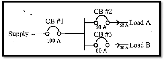
[image:19.612.169.455.196.303.2]A protection system must be able to discriminate between healthy and faulty equipment and circuits. It can be achieved by current (magnitude), time and comparison. The simple radial distributions network system as shown in Figure 2.1.
Figure 2.1: Simple radial distributions.
The CB 1 is set to trip at 100A and CB 2 and CB 3 is set to trip at 60A. After that, current drawn by a load A is 65 A and load B is 30A. CB 2 will trip since current drawn exceed 60A. CB 1 will not trip since total current drawn is 95 A and less than 100A. For this case, discrimination between CB 1 and CB 2 is archived by current grading.
Figure 2.2: Time delay for each CB.
The minimum time interval is usually between 0.3 and 0.5s. It is required to prevent simultaneous tripping. CB 1 is set to trip at 100A at 0.7s. CB 2 and CB 3 is set to trip at 60A at 0.2s. Then, current drawn by load A is 90A and load B is 30A. After that, CB 2 will trip first since current drawn by exceed 60A and shorter time delay. CB 1 will not trip since longer time delay. There will be no supply for load A and load B is still operating. This discrimination between CB 1 and CB 2 is achieved by time grading.
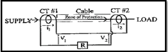
A differential (or comparison) protection system compares the current flowing into equipment (i.e. cable, transformer) with the current flowing out. If there a difference, the protection will operate. The differential protection system is used for protection „a piece‟ of equipment such as a cable or a transformer. It is calling a „unit‟ of protection system.
Figure 2.4: Balanced voltages.
2.1.2 Earth Fault Protection
Faults studies form essential things of power system. The issue consists of determining bus voltage and line currents throughout various sorts of faults. Faults on power are separated into two which is balanced and unbalanced faults. Types of unbalanced faults are single line to ground faults, line to line faults and double line to ground faults [5].
A fault in a circuit is any breakdown which will disturbs with the normal flow of current. The faults are associated with abnormal change in current, voltage and frequency of the power system. Faults occurs in a power system due to insulation breakdown of equipment, flashover of lines initiated by lightning stroke and because of permanent damage to conductors [6].
The lower configurations allowable for earth-fault relays are really helpful. Earth faults are not only by far the many of all faults, but may be restricted in magnitude by the neutral earthing impedance. The basic connection shown in Figure 2.5 can be prolonged by connecting overcurrent elements in the individual phase leads, as shown in Figure 2.6, and applying the earth-fault relay between the star points of the relay group and the current transformer.
[image:22.612.149.475.321.472.2]Phase fault overcurrent relays are frequently supplied on only two phases since these will identify any interphase fault; the connections to the earth-fault relay are not affected by this concern. The setup is shown in Figure 2.7.The typical settings for earth-fault relays are 30%-40% of the full-load current or minimum earth-fault current on the part of the system being guarded.
Figure 2.5: Residual connection of fault transformer to earth fault relays.
[image:22.612.148.478.529.681.2]Figure 2.7: Residual connection of fault transformer to earth fault relays.
2.1.3 Relay Coordination Concept 2.1.3.1 Radial System
2.1.4 Relay Current Setting
An overcurrent relay has a minimum operating current, known as the current setting of the relay. The current setting must be chosen so that the relay does not operate for the maximum load current in the circuit being protected, but does operate for a current equal or greater to the minimum expected fault current. Although by using a current setting that is only just above the maximum load current in the circuit a certain degree of protection against overloads as well as faults may be provided, the main function of overcurrent protection is to isolate primary system faults and not to provide overload protection.
[image:24.612.98.527.435.675.2]In general, the current setting will be selected to be above the maximum short time rated current of the circuit involved. Since all relays have hysteresis in their current settings, the setting must be sufficiently high to allow the relay to reset when the rated current of the circuit is being carried. The amount of hysteresis in the current setting is denoted by the pick-up/drop-off ratio of a relay – the value for a modern relay is typically 0.95. Thus, a relay minimum current setting of at least 1.05 times the short-time rated current of the circuit is likely to be required.