i
UNIVERSITI TEKNIKAL MALAYSIA MELAKA
DEVELOPMENT OF PORTABLE MINI THERMOELECTRIC
GENERATOR FOR OUTDOOR ACTIVITIES AND
EMERGENCY SITUATIONS BY USING PCM-COOLED
THERMOELECTRIC MODULE
This report submitted in accordance with requirement of the Universiti Teknikal Malaysia Melaka (UTeM) for the Bachelor Degree of Engineering Technology
(Automotive Technology) with Honours
by
MUHAMMAD ZAKI BIN ZAHRI B071310576
940110-10-6317
ii
APPROVAL
This report is submitted to the Faculty of Engineering Technology of UTeM as a partial fulfillment of the requirements for the degree of Bachelor Degree of Engineering Technology (Automotive Technology) with Honours. The member of the supervisory is as follow:
iii ** Jika Laporan PSM ini SULIT atau TERHAD, sila lampirkan surat daripada pihak berkuasa/organisasi berkenaan dengan menyatakan sekali sebab dan tempoh laporan PSM ini perlu dikelaskan sebagai SULIT atau TERHAD.
Cop Rasmi:
Tarikh: _______________________
UNIVERSITI TEKNIKAL MALAYSIA MELAKA
BORANG PENGESAHAN STATUS LAPORAN PROJEK SARJANA MUDA
TAJUK: Development of Portable Mini Thermoelectric Generator for Outdoor Activities and Emergency and Emergency Situations by using PCM-cooled Thermoelectric Module
SESI PENGAJIAN: 2016/17 Semester 1
Saya MUHAMMAD ZAKI BIN ZAHRI
mengaku membenarkan Laporan PSM ini disimpan di Perpustakaan Universiti Teknikal Malaysia Melaka (UTeM) dengan syarat-syarat kegunaan seperti berikut: 1. Laporan PSM adalah hak milik Universiti Teknikal Malaysia Melaka dan penulis. 2. Perpustakaan Universiti Teknikal Malaysia Melaka dibenarkan membuat salinan
untuk tujuan pengajian sahaja dengan izin penulis.
3. Perpustakaan dibenarkan membuat salinan laporan PSM ini sebagai bahan pertukaran antara institusi pengajian tinggi.
4. **Sila tandakan ( )
SULIT (Mengandungi maklumat yang berdarjah keselamatan atau kepentingan Malaysia sebagaimana yang termaktub dalam AKTA RAHSIA RASMI 1972)
(Mengandungi maklumat TERHAD yang telah ditentukan oleh organisasi/badan di mana penyelidikan dijalankan) TIDAK TERHAD
TERHAD
C-4-10 Jalan Putra Perdana 5F
Taman Putra Perdana
47130 Puchong, Selangor
Tarikh: ________________________
Disahkan oleh:
iv
DECLARATION
I hereby, declared this report entitled Development of Portable mini Thermoelectric Generator for Outdoor Activities and Emergency Situations by
using PCM-cooled Thermoelectric Module is the results of my own research except as cited in references.
Signature : ……….
Author’s Name : ………
1
ABSTRAK
Penjana termoelektrik (TEG) adalah alat yang menukarkan tenaga haba kepada tenaga elektrik berasaskan prinsip kesan Seebeck. Komponen utama TEG adalah modul termoelektrik. Apabila terdapat perbezaan suhu antara permukaan panas dan permukaan sejuk modul termoelektrik, tenaga elektrik akan terhasil. Jumlah tenaga elektrik yang terhasil amat dipengaruhi oleh perbezaan suhu antara permukaan panas dan permukaan sejuk modul termoelektrik. Semakin tinggi perbezaan suhu, semakin tinggi tenaga elektrik yang dihasilkan. Bagaimanapun, apabila permukaan panas termoelektrik dipanaskan, permukaan sejuk turut menjadi panas disebabkan oleh pemindahan haba daripada sumber haba. Oleh itu, permukaan sejuk modul termoelektrik perlu disejukkan dengan berkesan. Objektif projek ini adalah untuk mengkaji kesan penggunaan bahan perubahan fasa (PCM) sebagai medium penyejukan pada permukaan sejuk modul termoelektrik. Prototaip TEG telah direka menggunakan perisian CATIA. Pada dasarnya, TEG dibuat dari modul termoelektrik, plat aluminium, penyingkir haba aluminium dan pendawaian elektrik. Sumber haba ialah api lilin. Sebagai tambahan pada penyingkir haba aluminium, parafin PCM telah digabungkan dengan penyingkir haba sebagai medium penyejukan pada permukaan sejuk modul termoelektrik. Hasil kajian menunjukkan bahawa PCM berkesan mengurangkan suhu permukaan sejuk sebanyak 2~3 0C dan
2
ABSTRACT
Thermoelectric generator (TEG) is a device that convert heat energy to electrical energy based on the principles of Seebeck effect. The main component of thermoelectric generator is thermoelectric module. When there is difference in temperature between the hot side and cold side of thermoelectric module, electricity is generated. The amount of electricity generated is greatly influenced by the temperature difference between the hot and cold sides of the thermoelectric module. The higher the temperature difference, the higher the amount of electricity produced. However, when the hot side of the module is heated, the cold side tends to become hot too due to heat transfer from the heat source. Therefore, the cold side of the thermoelectric module needs to be cooled effectively. The objective of this project is to investigate the effectiveness of using paraffinic Phase Change Material (PCM) as a cooling medium at the cold side of thermoelectric module. Prototype of TEG were designed by using CATIA software. TEG basically made of thermoelectric module, aluminium plate, aluminium heat sink and electrical wiring. The heating source was candle flame. In addition to aluminium heat sink, paraffinic PCM was incorporated into the heat sink as a cooling medium for the cold side of the thermoelectric module. The results shows that PCM effectively reduced the temperature of the cold side by 2~3 0C and resulted in higher voltage generation by the TEG as compared that of
3
DEDICATION
This project and research work is dedicated to my beloved parents for their enthusiastic caring throughout my life, my loving siblings and also my friends for
4
ACKNOWLEDGEMENT
5
TABLE OF CONTENTS
Abstrak v
Abstract vi
Dedication vii Acknowledgement viii
Table of Content ix
List of Tables xiii
List of Figures xiv
List of Abbreviations and Symbols xvi
CHAPTER 1: INTRODUCTION 1
1.0 Introduction 1
1.1 Project Background 1
1.2 Thermoelectric Effect 4
1.3 Thermoelectric Module 4
1.3.1 Heating and Cooling Source 5
1.3.2 Phase Change Material (PCM) 5
1.4 Problem Statement 6
1.5 Objectives 7
1.5.1 General Objectives 7
1.5.2 Specific Objectives 8
6
CHAPTER 2: LITERATURE REVIEW 9
2.0 Introduction 9
2.1 History of Thermoelectric Generator 9
2.2 Thermoelectric Module 10
2.2.1 Thermoelectric Material 11 2.2.2 Mechanism of Thermoelectric Generation 12
2.3 Development of Thermoelectric Generator 13
2.3.1 Automotive Thermoelectric Generator 13 2.3.2 Camping Stove Thermoelectric Generator 14
2.4 Cooling Source of Thermoelectric Module 15
2.5 Phase Change Material (PCM) 15
2.6 Categories of Phase Change Material 16 2.6.1 Organic Phase Change Material 16 2.6.2 Inorganic Phase Change Material 16
2.6.3 Eutectics 17
2.7 Advantages and Disadvantages of Phase Change Material 17 2.8 Efficiency of Thermoelectric Generator 17 2.8.1 Principle of Seebeck Coefficient 18 2.8.2 Principle of Electrical Conductivity
19 2.8.3 Principle of Thermal Conductivity 19
2.9 Figure of Merit 20
7
CHAPTER 3: METHODOLOGY 21
3.0 Introduction 21
3.1 Main Steps in Developing Thermoelectric Generator 21
3.2 Initial Prototype of TEG 23
3.2.1 General Features 23
3.2.2 Fabrication Procedures 24
3.3 Final Prototype of TEG 24
3.3.1 General Features 24
3.3.2 Fabrication Procedures 25
3.4 Main Components of Final Prototype 26
3.4.1 Fastener 27
3.4.2 Perspex 27
3.4.3 Cover 28
3.4.4 Aluminium Heat Sink 28
3.4.5 Thermoelectric Module 29
3.4.6 Main Body 30
3.4.7 DC-DC Converter Step-up Boost Module with USB 31
3.4.8 Aluminium Plate 32
3.4.9 Phase Change Material 32
3.5 Electrical Device Measurement 34
3.5.1 Thermocouple 34
3.5.2 Multimeter 34
3.5.3 Power Bank 35
8 3.5.5 Measurement of Charging Rate of Power Bank 36
CHAPTER 4: RESULT & DISCUSSION 37
4.0 Introduction 37
4.1 Fabrication of Initial Prototype 37
4.2 Fabrication of Final Prototype 38
4.3 The Best Parameters for Thermoelectric Generator 39 4.3.1 Effect of Types of Thermoelectric Module 39 4.3.2 Effect of Number of Thermoelectric Module 41 4.3.3 Effect of Using Phase Change Material 42
4.3.4 Power Bank Charging Rate 45
4.3.5 PCM Physical Changes 47
CHAPTER 5: CONCLUSION & FUTURE WORK 49
5.0 Introduction 49
5.1 Summary of Research 49
5.2 Significant of Research 51
5.3 Achievement of Research Objectives 51
5.4 Suggestion of Future Works 51
5.5 Few Improvement Items 52
9
LIST OF TABLES
No. Title Page
2.1 Energy band gap eV for several thermoelectric materials 11 2.2 Advantages and disadvantages of paraffinic PCM 17
3.1 Description of the Main Steps 22
3.2 List of Materials in Developing Final Prototype of TEG 26
3.3 Specification of TEM (TEP1-142T300) 30
3.4 Specification of Converter Step-up Boost Module 31
3.5 Specification of Power Bank (PINENG PN-999) 36
4.1 Comparison data between different types of thermoelectric modules
40
4.2 Comparison data of different number thermoelectric modules 41 4.3a TEG performance using aluminium heat sink without PCM 43 4.3b TEG performance using aluminium heat sink with PCM 43
4.4 Charging rate of power bank 46
10
LIST OF FIGURES
No. Title Page
1.1 Basic function of smartphones 1
1.2 Necessity of electricity source during outdoor activities 2
1.3 Flood in Kota Bharu, Kelantan in 2015 3
1.4 Basic principle of Seebeck effect 4
1.5 A thermoelectric module 5
1.6 Phase change of PCM 6
1.7 Thermoelectric module problem 7
2.1 Major discovery of thermoelectricity 9
2.2 Basic components of a thermoelectric module 10
2.3 Mechanism of how a thermoelectric module works 12 2.4 Installation of thermoelectric generator in a suburban car 14
2.5 A wood burning camp stove 14
2.6 Phase change of PCM in response to temperature change 16 2.7 Graph of Seebeck Coefficient for several materials 18 3.1 Main steps in developing mini thermoelectric generator 21
3.2 Isometric view of initial prototype TEG 23
3.3 Isometric view of the final prototype TEG 25
3.4 Fastener 27
3.5 Perspex 27
3.6 Cover 28
3.7 Aluminium heat sink 29
3.8 Thermoelectric module (TEP1-142T300) 29
3.9 Isometric view of the main body 30
3.10 DC-DC converter step-up boost module with USB 31
11 3.12 Phase change material in aluminium heat sink 33 3.13 Graph of melting point and heat of fusion of paraffinic PCM 33 3.14 Circuit connection of TEG with electrical devices 34
3.15 Multimeter 35
3.16 Power Bank (PINENG PN-999) 35
4.1 Initial prototype set-up 37
4.2 Exploded view of final prototype TEG 38
4.3 Comparison graph between different types of thermoelectric modules
40
4.4 Comparison graph between different numbers of thermoelectric module
42
4.5 Effect of PCM on voltage produced 44
4.6 Effect of PCM on cold side temperature of the module 45
4.7 Measuring power bank charging rate 45
4.8 Graph of cumulative percentage against time 47
4.9 Melting PCM 48
5.1 Final prototype of TEG 50
5.2 The effect of PCM on the cold side of the module 50
12
LIST OF ABBREVIATIONS AND SYMBOLS
A - Cross-sectional Area
ATGs - Automotive Thermoelectric Generators Bi2Te3 - Bismuth Telluride
CnH2n+2 - Paraffin
CH3(CH2)n COOH - Fatty Acids
c - Specific Heat
DSC - Differential Scanning Calorimetry
E - Intensity of the Electric Field
FTP - Federal Test Procedure
I - Current
J
- Current DensityL - Length
LHS - Latent Heat Storage
MnH2O - Salt Hydrates
n - Negative type
PCM - Phase Change Material
Pd - Palladium
p - Positive type
S - Seebeck Coefficient
13
TEM - Thermoelectric Module
T1 - Temperature 1
T2 - Temperature 2
t - Time
V - Voltmeter/Voltage
W - Thermal Power
zT - Figure of Merit
α - Thermal Diffusivity
σ - Electrical Conductivity
κ - Thermal Conductivity
η
- EfficiencyΔV - Thermoelectric Voltage
ΔT - Temperature Difference
TH - Hot Side Temperature
14
CHAPTER 1
INTRODUCTION
1.0 Introduction
This chapter explains the background of this study. The explanation is then extended to the problem statement, objectives and scope which clarifies the main concepts in designing portable mini thermoelectric generator.
1.1 Project Background
Nowadays, outdoor activities such as mountain climbing, camping in the forest, lake or waterfall and island hoping are very popular among teenagers. This adventurous activities motivate them to boost their physical and mental strength.
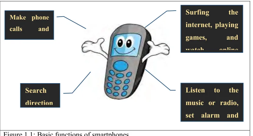
[image:18.595.108.524.508.732.2]During these activities, modern gadgets such as smart phones and high resolution camera are used frequently to take photos of beautiful sceneries or their activities as their life-time memory. The smart phone also can function as a compass to know direction of a place or to determine the kiblah to perform Solah for the Muslims. Figure 1.1 shows some basic functions of smartphones.
Figure 1.1: Basic functions of smartphones
Surfing the
internet, playing
games, and
watch online
television
Make phone
calls and
sending texts messages
Listen to the music or radio, set alarm and taking photos Search
15 The basic function of smartphones is to ease of communication especially in getting the information from various sources such as the internet, phone call and text messages. Thus, in many situations these communication gadgets are important for people to get information and to make contact with others in various ways.
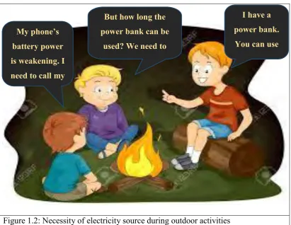
[image:19.595.109.521.289.607.2]However, the electrical source of these gadgets need to be recharged from time to time due to weakening of battery life. In order to solve the problem of accessing electricity during outdoor activities, a power bank, an electrical energy storing device is used to charge the gadgets. Yet, the power bank also needs to be charged. Figure 1.2 illustrates the importance of accessing source of electricity during outdoor activities.
Figure 1.2: Necessity of electricity source during outdoor activities
Source of electricity is extremely important during outdoor activities to supply energy to electricity-operated devices such as hand phones, torch light, fan and many others. In fact, this requirement is crucial in preventing difficulties that may happen in the future.
Source of electricity is also indispensable during or after the natural disaster such as flood, earthquake, typhoon and hurricane in which the electrical supply
My phone’s battery power is weakening. I need to call my
mom.
I have a power bank.
You can use mine. But how long the
power bank can be used? We need to
16 possibly will be cut off. An electrical energy is needed to get assistance from the outside. Big flood which frequently attacks many areas in Malaysia cause many adverse effects including the shut-down of electricity supply.
[image:20.595.108.532.212.526.2]In the end of December 2015, a heavy raining fall in Kelantan for a several days. Figure 1.3 shows the photo of Stadium Muhammad IV that had been immersed in water caused by the big flood attack.
Figure 1.3: Big flood in Kota Bharu, Kelantan in 2015
17 1.2 Thermoelectric Effect
Thermoelectric generator is a device that convert heat energy to electrical energy through a phenomenon known as Seebeck effect. It is based on the principle that a temperature difference across thermoelectric material can be converted directly into electrical power.
When two different metal wires are connected at both ends (junctions) ordinarily nothing will happen. After one of the junction end is heated, a current is produced continuously in the circuit. This phenomenon is called as Seebeck effect. The circuit that incorporates both thermal and electric effect is called thermoelectric circuit. As shown in Figure 1.4, when one of the junctions of two dissimilar metals is heated, a current I flows through the closed circuit.
Figure 1.4: Basic principle of Seebeck effect
When heat is supplied from a candle to one junction of metal A and metal B, a current is produced flowing through the connection of the closed circuit. Nowadays, scientists are developing thermoelectric modules that can generate electricity by applying the same principle.
1.3 Thermoelectric Module
Thermoelectric module is the main component of thermoelectric generator. It consists of two sides; a hot side and a cold side. When heat is applied to the hot side of the thermoelectric module, electricity will be generated. The cold side is the side of thermoelectric module that is needed to be cooled effectively. The amount of the electricity generated are greatly affected by the temperature gradient between the hot
I
I
T1:Temperature 1 T2: Temperature 2
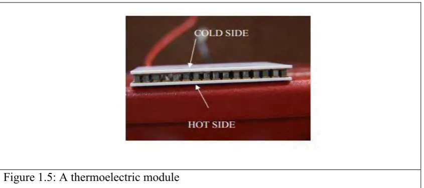
18 side and cold side of the module. The higher the temperature gradient, the more electricity is generated. Figure 1.5 shows the photo of a thermoelectric module.
Figure 1.5: A thermoelectric module
In order to generate the electricity, heating and cooling sources need to be supplied to the hot and cold sides of thermoelectric module.
1.3.1 Heating and Cooling Source
Heating and cooling sources are important to thermoelectric module in generating electricity since it depends on temperature differences between the hot and cold sides of the thermoelectric module. Examples of heating sources are lighting candle, hot water, solar heat and many others. In automotive vehicles, there are also several potential heating sources such as heat from the car engine and hot exhaust gas. Meanwhile, the cooling sources are metal heat sink, ice pack, cold water, paraffin and several others.
1.3.2 Phase Change Material (PCM)
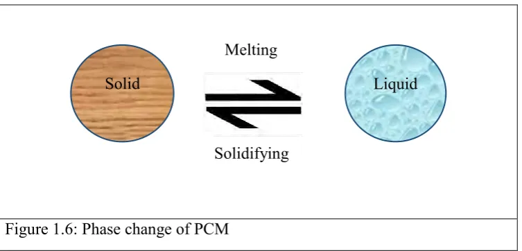
19 processes. Figure 1.6 illustrates the change in PCM phases when it experiences melting or freezing processes.
[image:23.595.145.522.117.298.2]
Figure 1.6: Phase change of PCM
PCM change their state from solid to liquid when heat energy is provided, which means it act as heat energy absorber. Meanwhile when PCM undergoes cooling process, it will change to solid from liquid state while releasing the same amount of heat energy.
1.4 Problem Statement
During camping in jungles, people are normally at remote areas where there is no source of electricity to recharge their electrical gadgets. Similar situations can happen during natural disasters such as flood or earthquake in which the affected areas may experience electricity shut down. In these situations, electricity is extremely important to contact outsiders for assistance. Thus, a portable mini thermoelectric generator should be developed to ease people to get access to electricity in these situations.
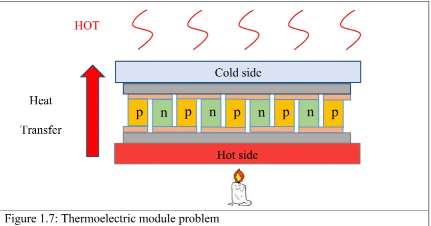
The main component of the thermoelectric generator is thermoelectric module. The hot side of the module is where heat sources is supplied to while the cold side is supposed to be cooled. The problem is, however, when heat is applied to the hot side of the thermoelectric module, the electricity will be produced but the cold side of the module also tends to get hot. This will reduce the temperature difference between the hot and cold sides of the thermoelectric module which in turn reduce the amount of electricity generated. This problem is illustrated in Figure 1.7.
Solid Liquid
Melting
20 Note that the cold side thermoelectric module also getting hotter due to the heat transfer from the hot side of the module.
Figure 1.7: Thermoelectric module problem
Due to the heat transfer, thermoelectric module become less efficient in generating electric current. This is due to the low temperature difference between the hot side and cold side of the module. This phenomenon can simply verified by touching by bare hand the cold side of the module. When the hot side is heated, the cold side also getting hotter. Therefore, in this study, paraffinic PCM was used (in addition to aluminium heat sink) as a cooling medium to the cold side of thermoelectric module to create high temperature difference between the both sides of the module and keep the cold side at low temperature.
1.5 Objectives
In order to achieve this project successfully, several objective were established.
1.5.1 General Objectives:-
To develop a portable mini thermoelectric generator for outdoor activities and emergency situations by using phase change material (PCM)-cooled thermoelectric module.
n
n
p
p
p
p
Hot side
n
p n
HOT
Heat Transfer