TEMPERATURE CONTROL SYSTEM USING ZIGBEE WIRELESS NETWORKING
NURHAMIZAH BINTI ABDUL MUSID
This report is submitted in partial fulfillment of the requirements for the award of Bachelor of Electronic Engineering (Industrial Electronics) With Honours
Faculty of Electronic and Computer Engineering Universiti Teknikal Malaysia Melaka
UNIVERSTI TEKNIKAL MALAYSIA MELAKA
FAKULTI KEJURUTERAAN ELEKTRONIK DAN KEJURUTERAAN KOMPUTER
BORANG PENGESAHAN STATUS LAPORAN
PROJEK SARJANA MUDA II
Tajuk Projek : TEMPERATURE CONTROL SYSTEM USING ZIGBEE WIRELESS
NETWORKING
Sesi Pengajian : 2010/2011
Saya NURHAMIZAH BINTI ABDUL MUSID
mengaku membenarkan Laporan Projek Sarjana Muda ini disimpan di Perpustakaan dengan syarat- syarat kegunaan seperti berikut:
1. Laporan adalah hakmilik Universiti Teknikal Malaysia Melaka.
2. Perpustakaan dibenarkan membuat salinan untuk tujuan pengajian sahaja.
3. Perpustakaan dibenarkan membuat salinan laporan ini sebagai bahan pertukaran antara institusi pengajian tinggi.
4. Sila tandakan ( √ ) :
(Mengandungi maklumat yang berdarjah keselamatan atau kepentingan Malaysia seperti yang termaktub di dalam AKTA RAHSIA RASMI 1972)
(Mengandungi maklumat terhad yang telah ditentukan oleh organisasi/badan di mana penyelidikan dijalankan)
Disahkan oleh:
(COP DAN TANDATANGAN PENYELIA)
Tarikh: SULIT* TERHAD* TIDAK TERHAD (TANDATANGAN PENULIS) Alamat Tetap:
NO 110, JALAN SELASIH 4, TAMAN SERI BAYU, 78000 ALOR GAJAH, MELAKA
iii
“I hereby declare that this report is the result of my own work except for quotes as cited in the references”
Signature : ……….
Author : Nurhamizah Binti Abdul Musid
iv
“I hereby declare that I have read this report and in my opinion this report is sufficient in terms of the scope and quality for the award of Bachelor of Electronic
Engineering (Industrial Electronics) With Honours.”
Signature : ……….
Supervisor‟s Name : Encik Fakrulradzi Bin Idris
v
To my beloved family, for their genuine love, prayers and encouragement. To my supervisor and all lecturers who guide me, and to all my friends for your help and
vi
ACKNOWLEDGEMENT
vii
ABSTRACT
viii
ABSTRAK
ix
TABLE OF CONTENTS
CHAPTER TITLE PAGE
TITLE i
REPORT STATUS APPROVAL FORM ii
DECLARATION iii
SUPERVISOR APPROVAL iv
DEDICATION v
ACKNOWLEDGEMENT vi
ABSTRACT vii
ABSTRAK viii
TABLE OF CONTENTS ix
LIST OF TABLES xiii
LIST OF FIGURES xiv
LIST OF ABBREVIATIONS xvi
LIST OF APPENDIXES xviii
I INTRODUCTION
1.1 Overview 1
1.2 Project background 1
1.3 Overview of project 2
1.4 Problem statement 2
1.5 Objective of project 3
1.6 Scope of project 3
1.7 Thesis outline 4
x
II LITERATURE REVIEW
2.1 Overview 6
2.2 Wireless sensor network 6
2.3 Sensor node 7
2.4 Multi-hop communication technique 9
2.5 Zigbee protocol 10
2.5.1 Technology overview 10
2.5.2 IEEE802.15.4 standard 11
2.6 Xbee/Xbee-PRO OEM RF modules 12
2.6.1 Advantages of Xbee 14
2.6.2 The pin signal 14
2.6.3 The electrical characteristic 16
2.7 Microcontroller 17
2.7.1 Pins description 19
2.7.2 PIC 16F877A block diagram 19
2.8 Zigbee versus Bluetooth 20
2.8.1 About Zigbee standard 22
III METHODOLOGY
3.1 Overview 24
3.2 Project planning 24
3.3 The overall structure of the project 25
3.4 Project overview 27
3.5 Hardware development 27
3.5.1 Transmitter circuit 27
3.5.1.1 Voltage regulator 28
3.5.1.2 LM35DZ temperature sensor 29 3.5.1.3 LCD module (16x2) character 30
3.5.1.4 LCD connection 31
xi
3.5.2 Receiver circuit 33
3.5.2.1 PIC16F877A microcontroller 34
3.5.2.2 Buzzer 35
3.6 USART Asynchronous Mode 35
3.7 Wireless modules 36
3.7.1 Serial communications 37
3.7.2 UART data flow 37
3.7.3 Transparent operation 38
3.7.4 Flow control 39
3.8 SKXbee 40
3.9 Interface PIC16F877A with Xbee 42
3.10 General process in fabricating the 43 hardware development
3.10.1 Layout printing 44
3.10.2 UV exposure 44
3.10.3 Developing the image 45
3.10.4 Spray washing 45
3.10.5 Etching 46
3.10.6 Resist stripping 46
3.10.7 Scrub cleansing 46
3.10.8 Cutting and drilling 47
3.10.9 Soldering 47
3.11 Software development 48
3.11.1 Overview 48
3.11.1.1 X-CTU software 49
3.11.1.2 Proteus Professional 7.6 51
3.11.1.3 PIC C Compiler 52
IV RESULT AND ANALYSIS
4.1 Overview 53
xii
4.2.1 Transmitter circuit 53
4.2.1.1Design using Proteus Professional 7.6 54
4.2.1.2 PCB layout 54
4.2.1.3 Circuit for etching 55
4.2.2 Receiver circuit 56
4.2.2.1Design using Proteus Professional 7.6 56
4.2.2.2 PCB layout 57
4.2.2.3 Circuit for etching 57
4.3 Practical prototype demonstration 58
4.4 Analysis of overall project 61
V DISCUSSION AND CONCLUSION
5.1 Discussion 62
5.2 Conclusion 63
REFERENCES 64
APPENDIX A 66
APPENDIX B 67
xiii
LIST OF TABLES
NO TITLE PAGE
1.1 Project plan 5
2.1 Comparison between RF protocols 11
2.2 Xbee series 1 specification 13
2.3 Pin configuration Xbee 15
2.4 DC characterictics (VCC = 2.8-3.4 VDC) 16
2.5 ADC characteristics (operating) 16
2.6 ADC timing/ performance characteristics 17
2.7 Comparative statement of different communication 21 protocols
2.8 Zigbee and Bluetooth specification comparison 23
3.1 Xbee features 36
xiv
LIST OF FIGURES
NO TITLE PAGE
2.1 Wireless sensor network architecture 7
2.2 Sensor node architecture 8
2.3 The Multi-hop topology 9
2.4 Mesh networking 10
2.5 The Zigbee layered model 12
2.6 Xbee multipoint RF modules 13
2.7 Xbee RF module pin numbers 15
2.8 PIC 16F877A pins description 19
2.9 PIC 16F877A internal architecture 19
2.10 Among existing wireless technologies 21
2.11 Network layers that involved in the Zigbee module 23
3.1 Flowchart of Final Year Project 25
3.2 Basic block diagram 27
3.3 Transmitter block diagram 28
3.4 IC LM7805 28
3.5 Common regulator circuit 29
3.6 Schematic of LM35DZ 29
3.7 LM35DZ connection diagram 30
3.8 Liquid crystal display 31
3.9 LCD (16x2) character 31
3.10 4-bit LCD interface connection 32
3.11 LCD connection with PIC16F877A 33
3.12 Receiver block diagram 33
3.13 PIC16F877A microcontroller 35
xv
3.15 NRZ data format 36
3.16 System data flow diagram in a UART-interfaced 37 environment
3.17 UART data packet 0x1F 38
3.18 Internal data flow diagram 39
3.19 SKXbee board layout 40
3.20 Example of connection PIC16F877A microcontroller 41
3.21 SKXbee specification 42
3.22 Connection between Xbee, PIC16F877A and LCD 43
3.23 Ultra-Violet Ray exposed 44
3.24 Developer 45
3.25 Etching equipment 46
3.26 Cutting the PCB board 47
3.27 Drilling process 47
3.28 Soldering process 48
3.29 X-CTU window 49
3.30 X-CTU software in windows environments 50
3.31 ISIS professional window 51
3.32 PIC C Compiler window 52
4.1 Schematic diagram for transmitter circuit 54
4.2 PCB layout design of transmitter circuit 55
4.3 Circuit design on transparency paper 55
4.4 Schematic diagram for receiver circuit 56
4.5 PCB layout design of receiver circuit 57
4.6 Circuit design on transparency paper 58
4.7 Practical prototype demonstration with hair dryer 58
4.8 Inside view of transmitter box prototype 59
4.9 Inside view of receiver box prototype 59
4.10 Complete set of the prototype 60
xvi
LIST OF ABBREVIATIONS
WSN - Wireless Sensor Network
IEEE - Institute for Electrical and Electronics Engineers LR- WPAN - Low rate Wireless Personal Area Network LCD - Liquid Crystal Display
RF - Radio Frequency
MAC - Media Access Control PCB - Printed Circuit Board
PIC - Programmable Integrated Circuit DSP - Digital signal processors
LoWPANs - Low Power Wireless Personal Area Networks FYP - Final year project
IC - Integrated Circuit LED - Light Emitting Diode
PHY - Physical layer
ADC - Analog to digital converters CPU - Central processing unit
CU - Control unit
DC - Direct current
RAM - Random access memory
ROM - Read only memory
EPROM - Erasable programmable read only memory
EEPROM - Electrically erasable programmable read only memory ISM - Industrial, scientific and medical radio band
xvii
FHSS - Frequency hoping spread spectrum DSSS - Direct sequence spread spectrum ISIS - ISIS schematic capture
VSM - Virtual system modeling
RSSI - Received signal strength indication RISC - Reduces Instruction Set Computer
UART - Universal Asynchronous Receiver Transmitter USART - Universal Synchronous Receiver Transmitter CTS - Clear to send frame
RTS - Request to send frame SPI - Serial Peripheral Interface NRZ - Non return to zero
I/O - Input and output
R/W - Read and write
xviii
LIST OF APPENDIXES
NO TITLE PAGE
A Specifications of Xbee 66
B Gantt chart for final year project 67
CHAPTER I
INTRODUCTION
1.1 Overview
This chapter will cover the introduction of the project where it involve of the project background, overview of project, problem statement, objective of project, scope of project, thesis outline and summary of work.
1.2 Project background
2
1.3 Overview of project
This project covers the implementation of temperature control wireless networking by using Zigbee. The IEEE802.15.4 Zigbee protocol is a wireless technology developed as an open global standard to address the unique needs of low cost, low power, wireless sensors network. Zigbee is generally used for home care, digital home control, industrial and security control. This project developed a suite of room care sensor network system by Zigbee‟s characteristic which is embedded sensors that is temperature sensor. The sensed temperature is converted to the digital form by the means of analog to digital converter and transmitted through Zigbee module and displayed on a local LCD display. On receiving end temperature is received through another Zigbee module and each acquisition of temperature is compared with a user defined set point. If this value exceeds the set point a control signal goes to a final control element or a buzzer.
1.4 Problem statement
3
1.5 Objectives of project
The aim of the project is to interface the smart wireless temperature data logger using IEEE802.15.4 Zigbee protocol. Hence, the sensed temperature can be measured throughout the LCD display. The temperature then compared with the set point. If it exceeds the set point, a control signal goes to a final control element or a buzzer. The specific objectives of these projects are:
a) To design and construct the transmitter and receiver circuit that will implement with Zigbee module
b) To interface the smart wireless temperature data logger using IEEE802.15.4 Zigbee protocol
c) To measure the performance of the signal range
1.6 Scope of project
4
1.7 Thesis outline
As a requirement in thesis format, it include by five chapters. In chapter I, it focuses on brief introduction of the project carried. The important things in this chapter are the problem statement, project objectives and project scopes are well emphasized in this part.
Chapter II normally is focused for literature review that covers related theory and previous works regarding this project are explained in this chapter. It discuss on the Wireless Sensor Network (WSN), Sensor node, Xbee/Xbee-PRO OEM RF modules, microcontroller and LM35DZ temperature sensor.
Chapter III consists of project methodology. It also includes information on research and experiment carried during the project development. It will explain on the concepts, theories and principles used in order to complete the project. In this chapter, the functional of each component which used has been explained clearly.
Chapter IV consists of result and analysis. It explains and focused for component description from the project. This chapter described the hardware and software system development.
5
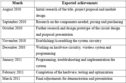
1.8 Summary of work
[image:23.595.105.525.245.522.2]Implementation and general works done are summarized in Table 1.1. It also includes the future works until this project is complete. The plan may change during the FYP 2 course.
Table 1.1: Project plan
Month Expected achievements
August 2010 Initial research of the title, project proposal and module design
September 2010 Research on the components needed, pricing and purchasing October 2010 Further research and design prototype of the circuit design
and proposal presentation
November 2010 Establishing/Assembling the system circuitry December 2010 Working on hardware circuitry, wireless system and
programming
January 2011 Programming, troubleshooting and implementation the system.
CHAPTER II
LITERATURE REVIEW
2.1 Overview
This chapter will introduce the term of Wireless Sensor Network (WSN), Sensor node, Zigbee protocol, Xbee/Xbee-PRO OEM RF modules, microcontroller, and Zigbee versus Bluetooth. The main objective of this chapter is to describe in details the above term and the role its play in this project.
2.2 Wireless Sensor Network (WSN)
Wireless Sensor Network consists of large numbers of sensor nodes. The nodes are equipped with sensor devices that are used for a certain applications. For example, the sensor device is camera and it is used to retrieve the environment data visually, microphone is used to detect the sound, thermometer and thermocouple are used to detect the changes in temperature.