SPEED CONTROL FOR DIRECT CURENT (DC) MOTOR WITH AN APPROACH OF FUZZY LOGIC NOR HALIMAHTUN SAADIAH BINTI MOHD
“I hereby declared that I have read through this report and found that it has comply The partial fulfillment for awarding the degree of Bachelor of Electrical Engineering
(Industrial Power)”
Signature: ……….. Co-Supervisor: Pn Elia Erwani Binti Hassan
SPEED CONTROL FOR DIRECT CURENT (DC) MOTOR WITH AN APPROACH OF FUZZY LOGIC
NOR HALIMAHTUN SAADIAH BINTI MOHD
This Report Is Submitted In Partial Fulfillment Of Requirements For The Degree Of Bachelor In Electrical Engineering (Industry Power)
Fakulti Kejuruteraan Elektrik
Universiti Teknikal Kebangsaan Malaysia, Melaka
“I hereby declared that this report is a result of my own work except for the excepts that have been cited clearly in the references.”
Signature : ……… Name : Nor Halimantun Saadiah Binti Mohd
iii
ACKNOWLEDGEMENTS
Assalamualaikum W.B.T
First of all I would like to thank Allah S.W.T because for HIS blessing, I have completed my final year project successfully.
I would like to extend my deepest gratitude to my supervisors Pn. Elia Erwani Hassan for her consistent supervision, guidance, support, and encouragement throughout this project.
My appreciation also goes to my beloved family for their patience and understanding throughout my studies in Universiti Teknikal Malaysia Melaka (UTeM).
Last but not least my thank goes to the person who directly and indirectly involved and contributed in completing this project and not to forget all my friends who give their full commitment and their best effort.
ABSTRACT
v
ABSTRAK
CONTENTS
CHAPTER TITLE PAGE
TITLE i
DECLARATION ii
ACKNOWLEDGEMENT iii
ABSTRACT iv
CONTENT vi
LIST OF TABLE ix
LIST OF FIGURE x
1 INTRODUCTION 1
1.1 Introduction 1
1.2 Problem Statement 2
1.3 Project Objective 2
1.4 Project Scope 3
1.5 Report Outline 3
2 LITERATURE REVIEW 4
2.1 Introduction of DC Motor Speed Control 5 2.2 Introduction to Fuzzy Logic 11 2.3 The Fuzzy Logic Toolbox 2.1 23
2.4 Fuzzy Clustering 31
2.5 Simulating and Deploying Fuzzy
vii
3 FUZZY LOGIC SPEED CONTROL
OF A DC MOTOR 33
3.1 Introduction 33
3.2 Motor Model 34
3.3 Fuzzy Logic Controller (FLC) Description 37 3.4 Fuzzy Logic Controller (FLC) Design 38
3.5 Control Simulation 45
3.6 Controller Implementation 47
4 PROJECT METHODOLOGY 52
4.1 Introduction 52
4.2 The Project Methodology 53
4.3 The Project Planning 55
5 SYSTEM DEVELOPMENT 56
5.1 Define the Number of Input and Output
and the FIS 57
5.2 Defining the Membership Function of the
Input and Output. 59
5.3 Defining the System Rules 62 5.4 Viewing the Whole System for Analysis 64
6 RESULT AND ANALYSIS 66
6.1 Introduction 66
6.2 Result 68
7 CONCLUSION AND DISCUSSION 75
7.1 Discussion 75
7.2 Suggestion 76
7.3 Conclusion 77
REFERENCES 79
APPENDIX A 81
ix
LIST OF TABLE
NO TITLE PAGE
3.1 The Parameter of DC Motor 35
3.2 The Rules Data Base 42
3.3 Performance of Analysis of Control 46
5.1 Fuzzy Linguistic Terms 54
5.2 Initial Rules 63
LIST OF FIGURE
NO TITLE PAGE
2.1 DC Motor Equivalent Circuit 7
2.2 A Simple Block Diagram of the Speed Controller 9 2.3 The Graph of the Speed of A Motor That Being Turned
on and Off Fairly 10
2.4 General Functional Block 12
2.5 The Classical Set and Fuzzy Set 13
2.6 The Membership Function 14
2.7 Membership Functions Representing Different
Seasons of the Year 15
2.8 Superset of Standard Boolean Logic 16 2.9 The Customized AND and OR Operators 17
2.10 The Tipping Problem Rules 21
2.11 The Membership Functions Editor 25
2.12 The FIS Editor 26
2.13 The Rule Editor 27
2.14 The Rule Viewer 28
2.15 The Three-Dimensional Plots 30
xi
3.5 Change of Error 40
3.6 Dynamic Signal Analysis 40
3.7 Linguistic rules for angle (U) determination
for Driver Circuit 43
3.8 FLC Simulink Model 45
3.9 Hardware Block Diagram 48
3.10 Level Shifter Circuit 49
3.11 Flowchart of the Algorithms running on the FLC. 51
4.1 The Project Planning Flowchart 55
5.1 Block Diagram of FLC 58
5.2 Initial Error (E) Membership Functions 60 5.3 Initial Change of Error (CE) Membership Function 61 5.4 The Initial Armature Voltage (CU) Membership
Functions 62
5.5 Fuzzy Toolbox 2.1 Rules Editor 64
5.6 The Rules Viewer of the System 65
6.1 The Membership Function of the System 68 6.2 The Adjustment of Membership Functions 69
6.3 Rules Editor for Final Result 71
6.4 The Rules Viewer for Final Result 72
6.5 DC Motor Speed Control 73
CHAPTER 1
INTRODUCTION
1.1 Introduction
The speed control is one of important component in Direct Current motor (DC motor) operation. In controlling the speed of a DC motor, some improvement needs to be done toward speed regulation during transient loading conditions. The control includes a regulating circuit that having an output for controlling the armature voltage to the motor. An input speed reference signal corresponding to the desired speed is provided to the regulating circuit. A feedback signal proportional to armature voltage is also provided to the regulating circuit to establish an error signal for operating the control to regulate the voltage to the motor and therefore the motor speed.
2
For acquire an accurate of fuzzy, Fuzzy Logic Toolbox 2.1 which is one of the applications in MATLAB software is used. Generally, in fuzzy logic system it is most important to define the range of input and output membership function in the fuzzy inference engine. Then, with the appropriate fuzzy rules, the accurate controlling system will be developed for the DC motor speed control. Therefore, the speed of DC Motor that used Mamdani-style fuzzy inference system, which is composed of each one of input, and of output variable.
1.2 Problem Statement
The PI and PID controller have been used as control method of servo driving in industrial control field. The driving specific property can be indicated well, a control constant is a property set. But the property constant need to be changed in order to maintain the optimum driving state if the driving point or the motor parameters are changed. Recently the fuzzy controller has appeared which is based on knowledge or an experience of expert rather than on a complicate mathematical modeling. The fuzzy controller works well using experimental information even if not having mathematical modeling. Moreover, the fuzzy controller is capable of real time control using fuzzy rule base.
1.3 Project Objective
1.4 Project Scope
1.4.1 To simulate the speed control DC Motor within the value that needed using fuzzy logic operation.
1.4.2 To analysis the speed control DC Motor that had been set is varying within the value that needed.
1.5 Report Outline
This report contains of 7 chapters. Chapter 1 covers an introduction, an objective about the project and the problem statement of this project. Second chapter provides a literature review of this project which review some related work that had been done by other people.
The main part for this project explains in Chapter 4. This chapter describes the research and identify on DC motor and Fuzzy Logic, learning and developing project using Fuzzy Logic Toolbox 2.1, analysis the overall design system and, the final adjustment for the design to get the good performance system.
4
CHAPTER 2
LITERATURE REVIEW
Literature review was an activity for researcher to research about project or paper work that have been done by some one else. The research must be done in their scope of project, which means the research must be related to the projects that have been suggested. Paper work or journal that related with DC motor speed control should be take, as it can help in the future if problem occur. Beside that, it also helps in collecting theory background because journal or paper work is new from the theories that get from book.
In other word literature review has been done to make sure;
i. It can give reader the overview of the project that has been suggested from the project that already been done by someone else.
ii. The research will highlight the advantage or disadvantage of the project before.
iii. The process or methodology that has been use for the project before can be implementing to the project that have been suggested.
2.1 Introduction of DC Motor Speed Control
There are two common methods in use. The common ways in which the speed of DC machine can be controlled are by adjusting the field resistance, Rf and adjusting the
terminal voltage applied to the armature.
Reel drives require this kind of control. The dc motor's material is wound on a reel at constant linear speed and constant strip tension, regardless of diameter. In controlling the field resistances, the control is obtained by weakening the shunt-field current of the dc motor to increase speed and to reduce output torque for a given armature current. Since the rating of a dc motor is determined by heating, the maximum permissible armature current is approximately constant over the speed range. This means that at rated current, the dc motor's output torque varies inversely with speed, and the dc motor has constant-horsepower capability over its speed range.
DC motors offer a solution, which is good for only obtaining speeds greater than the base speed. A momentary speed reduction below the dc motor's base speed can be obtained by overexciting the field, but prolonged overexcitation overheats the dc motor. Also, magnetic saturation in the dc motor permits only a small reduction in speed for a substantial increase in field voltage.
DC motors have a maximum standard speed range by field control is 3:1, and this occurs only at low base speeds. Special dc motors have greater speed ranges, but if the dc motor's speed range is much greater than 3:1, some other control method is used for at least part of the range.
6
In armature-voltage DC motor speed control method, shunt-field current is maintained constant from a separate source while the voltage applied to the armature is varied. Dc motors feature a speed, which is proportional to the counter emf. This is equal to the applied voltage minus the armature circuit IR drop. At rated current, the torque remains constant regardless of the dc motor speed (since the magnetic flux is constant) and, therefore, the dc motor has constant torque capability over its speed range.
2.1.1 Changing the Field Resistance
In understanding the effect when the field resistor of a DC motor is changed, assume that the field resistor increase and observe the response. When the field resistance is increased, the field current will be decreased [6].
t f f V I R = (2.1)
As the field current is decreased, the flux, Φ decreased with it. A decreased in flux
caused an instantaneous decreased in the internal generated voltage,EA.
A
E =Kφ (2.2)
This caused a large increased in the machine’s armature current,IA.
The induced torque in a motor is given
ind K IA
τ = φ (2.4)
Since the flux in the machine is decreased while the current IA isincreased, this
does induce the torque, τ change. Since the τind>τload, the motor speed will be increase.
However, as the motor speed up, the internal voltage,EA will rises, causing IA to
fall. As IA falls, the induced torque τind falls too, and finally the τindagain equal to τ load
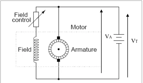
[image:20.612.184.478.369.541.2]at a higher steady-state speed than originally.
Figure 2.1: DC Motor equivalent circuit
(Source: http://homepages.which.net/~paul.hills/SpeedControl/SpeedControllersBody) VT
8
2.1.2 Changing the Armature Voltage
The second method in controlling the DC motor speed control involved the changing the voltage applied to the armature of the motor without changing the voltage applied to the field. A connection similar to Figure 1 is necessary for this type of control. In effect, the motor should be separately excited to use armature voltage control.
When the voltage VA is increased, then the armature current, IA in the motor
must rise. This situation based on Equation 2.3. As IA is increased, the induced torque,
ind
τ also increased and making τind>τloadand the speed, ω of the motor to increased.
But, as the speed increased, the internal generated voltageEA is increased and
causes the armature current to decrease. This situation will decreased the torque induced,
causing toτind equal to τload at a higher rotational speed, ω.
2.1.3 Speed Controller
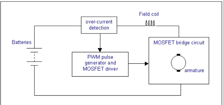
Motors come in a variety of forms, and the speed controller's motor drive output will be different dependent on these forms. The speed controller presented here is designed to drive a simple cheap starter motor from a car, which can be purchased from any scrap yard. These motors are generally series wound, which means to reverse the motor, they must be altered slightly.
Figure 2.2: A simple block diagram of the speed controller
(Source: http://homepages.which.net/~paul.hills/SpeedControl/SpeedControllersBody)
The speed of a DC motor is directly proportional to the supply voltage. The speed controller works by varying the average voltage sent to the motor. This can be done by simply adjusting the voltage sent to the motor, but this is quite inefficient to do. A better way is to switch the motor supply on and off very quickly. If the switching is fast enough, the motor does not notice it, this only notices the average effect.
10
Now imagine a light bulb with a switch. When the switch is closed, the bulb goes on and is at full brightness, says 100 Watts and when the switch is closed is 0 Watts. Now if the switch is closed in a fraction of a second and then opens for the same amount of time, the filament would not have time to cool down and heat up. This will just get an average glow of 50 Watts. This is how lamp dimmers work, and the same principle is used by speed controllers to drive a motor. When the switch is closed, the motor sees 12 Volts, and when the switch is open it sees 0 Volts. If the switch is open for the same amount of time as it is closed, the motor will see an average of 6 Volts, and will run more slowly accordingly. As the amount of time that the voltage is on increases compared with the amount of time that it is off, the average speed of the motor increases.
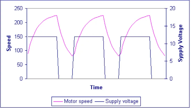
[image:23.612.144.508.418.624.2]The time that takes a motor to speed up and slow down under switching conditions is dependant on the inertia of the rotor (basically how heavy the motor), and how much friction and load torque there is.
From the graph, the average speed is around 150, although it varies quite a bit. If the supply voltage is switched fast enough, where no time to change speed much and the speed will be quite steady. This is the principle of switch mode speed control. Thus the speed is set by Pulse Width Modulation (PWM).
2.2 Introduction of Fuzzy Logic
The Fuzzy Logic was invented in 1965 by Professor Lotfi A. Zadeh of the University of California. Fuzzy logic is used around the world in many application areas such as control, instrumentation, laboratory automation, factory automation, system identification, system modeling and much more.
2.2.1 The Fuzzy Theory