UNIVERSITI TEKNIKAL MALAYSIA MELAKA
(UTeM)
MOTORIZED WORKTABLE FOR ROBOTIC
APPLICATION
Thesis submitted in accordance with the partial requirements of the Universiti Teknikal Malaysia Melaka for the
Bachelor of Manufacturing Engineering (Robotics and Automation)
By
NUR AISAMUDDIN BIN MOHAMAD
UTeM Library (Pind.1/2007)
UNIVERSITI TEKNIKAL MALAYSIA MELAKA
BORANG PENGESAHAN STATUS LAPORAN PSM
JUDUL:
MOTORIZED WORKTABLE FOR ROBOTIC APPLICATION
SESI PENGAJIAN: Semester 2 2007/2008
Saya NUR AISAMUDDIN BIN MOHAMAD
mengaku membenarkan laporan PSM / tesis (Sarjana/Doktor Falsafah) ini disimpan di Perpustakaan Universiti Teknikal Malaysia Melaka (UTeM) dengan syarat-syarat kegunaan seperti berikut:
1. Laporan PSM / tesis adalah hak milik Universiti Teknikal Malaysia Melaka dan penulis.
2. Perpustakaan Universiti Teknikal Malaysia Melaka dibenarkan membuat salinan untuk tujuan pengajian sahaja dengan izin penulis.
3. Perpustakaan dibenarkan membuat salinan laporan PSM / tesis ini sebagai bahan pertukaran antara institusi pengajian tinggi.
4. *Sila tandakan (√)
SULIT
TERHAD
TIDAK TERHAD
(Mengandungi maklumat yang berdarjah keselamatan atau kepentingan Malaysia yang termaktub di dalam AKTA RAHSIA RASMI 1972)
(Mengandungi maklumat TERHAD yang telah ditentukan oleh organisasi/badan di mana penyelidikan dijalankan)
(TANDATANGAN PENULIS) Alamat Tetap: QRTS KLINIK KESIHATAN KUALA KEMAMAN, KG. GELIGA,
24000 CHUKAI, KEMAMAN TERENGGANU DARUL IMAN
Tarikh: _______________________
(TANDATANGAN PENYELIA)
Cop Rasmi:
Tarikh: _______________________
APPROVAL
This thesis submitted to the senate of UTeM and has been accepted as fulfillment of the requirement for the Bachelor of Manufacturing Engineering (Robotics and Automation)
with Honors. The members of the supervisory committee are as follows:
………. Khairol Anuar Bin Rakiman
(PSM Supervisor)
DECLARATION
I hereby, declare this thesis entitled “MOTORIZED WORKTABLE FOR ROBOTIC APPLICATION” is the result of my own research except as cited in the
references.
Signature : ……….
Author’s Name : Nur Aisamuddin Bin Mohamad
ABSTRACT
ABSTRAK
ACKNOWLEDGEMENTS
First of all, I want to thank The Almighty God because of His permission that gives me strength to finish this report with successfully even many difficulties that had come. For my beloved parents Mohamad bin Mat Amin, Norkiah bt. Rani and all my family, thanks for all support that have been given in finishing this PSM.
Then, my PSM supervisor Mr. Khairol Anuar bin Rakiman that always gave guidance for me during this period and help me to complete this project. Beside that, I want to take these opportunities to thank to my entire lecture and technicians that teach me all the useful knowledge that I had used during this PSM.
TABLE OF CONTENTS
Abstract
Acknowledgements Table of Contents List of Figures List of Tables List of Diagram
i iii iv vii viii ix
1. INTRODUCTION 1
1.1 Project Background 1
1.2 Problem Statement 2
1.3 Project Objectives 2
1.4 Scope of the Project 3
2. LITERATURE REVIEW 4
2.1 Introduction 4
2.2 Robot Application 5
2.3 Relation between Existing Products with Motorized Work Table 6
2.4 Example of Motorized Work Table 9
2.4.1 Panasonic 3 Axis Model ISP Cartesian Robotic TIG Welding Cell 9
2.4.2 Interaction Adjustable Tables by Knoll 11
2.4.3 The Electrostrictive Worktable 13
2.4.4 The Ergonomic Worktable 16
2.5 Motorized 17
2.5.1 Electric motor 17
2.5.2 DC motors 19
2.5.3 AC Motors 22
2.5.4 Pneumatic Motor 26
3. METHODOLOGY 29
3.1 Introduction 29
3.2 Design Phase 32
3.2.1 SolidWorks Software 34
3.2.2 The Design Flow Process 35
3.3 Material Selection Phase 36
3.3.1 Introduction 36
3.3.2 Ashby Plots 37
3.3.3 Cost Issues 39
3.4 Simulation Phase 40
3.4.1 Introduction 40
4. RESULT AND ANALYSIS 42
4.1 Introduction 42
4.2 Design 42
4.2.1 Preliminary Design 42
4.2.2 Final Design 45
4.2.3 The Design View Each Part 48
4.2.4 Design Analysis 56
4.3 Simulation 57
4.3.1 Stroke at X-axis 57
4.3.2 Stroke at Y-axis 58
4.3.3 Stroke at Z-axis 60
4.4 Material Selections 61
4.4.1 Cost 61
4.4.2 Weight 61
4.4.3 Strength 61
4.4.4 Final Material Selection 62
4.5 Actuator Selection 62
5. DISCUSSION AND IMPROVEMENT 69
5.1 Introduction 69
5.2 Discussion 69
5.3 Improvement in Designing the Mechanisms 70
6. CONCLUSION 73
6.1 Conclusion 73
6.2 Recommendation and Future Work 74
REFERENCES 75
LIST OF FIGURES
2.1 RC505001 “2003 Panasonic 3 Axis Model ISP Cartesian Robotic TIG Welding Cell
9
2.3 Interaction Adjustable Tables 10
2.4 Moving Principle of the Worktable 13
2.5 Schematic Diagram of the Worktable 14
2.6 Ergonomic Workstation Adjustable Table 15
2.7 Motorized Adjustable Ergonomic Workstation Desk 16
2.8 The example of DC Motor 19
2.9 The Permanent Magnetic Brushless DC Motor 21
2.10 The AC Gear Motor 23
2.11 The Pneumatic Motor 26
2.12 The Hydraulic Motor 27
3.1 SolidWorks Software 34
3.2 Ashby Plot of Density and Young's Modulus 37
3.3 A Chart That Generated By the Material Grapher 38
4.1 The Sketch Development of Worktable Design 44
4.2 The isometric views of all assembly products 45
4.3 The orthographic view of the product 46
4.4 The isometric view of Part A 48
4.5 The orthographic view of the part A 49
4.6 The isometric view of Part B 50
4.7 The orthographic view of the part B 51
4.8 The isometric view of Part C 52
4.9 The orthographic view of the part C 53
4.11 The orthographic view of the part D 55 4.12 The movement of the stroke at X-axis (Before) 58
4.13 The movement of the stroke at X-axis (After) 58
4.14 The movement of the stroke at Y-axis (Before) 59
4.15 The movement of the stroke at Y-axis (After) 59
4.16 The movement of the stroke at Z-axis (Before) 60
4.17 The movement of the stroke at Z-axis (After) 60
4.18 Load Location on the top table 66
4.19 Stress for top table 67
4.20 Stress result table for top table 67
4.21 Displacement for top table 68
4.22 Displacement result table for top table 68
4.23 Design Check for FOS 69
5.1 The split pinion and rack 72
5.2 The Example of the Worm Gear at Gear Box 73
LIST OF DIAGRAM
3.1 The Process Flow In This Project 31
3.2 The Design Flow Process 36
LIST OF TABLES
2.1 The FILA Table 6
4.1 The part and its name 48
4.2 The Weight of Each Part with Each Material. 61
4.3 The Material Selection 63
4.4 The Relation Of The Stroke And Mass Involved 64
CHAPTER 1
INTRODUCTION
1.1 Project Background
Nowadays, robotic applications are widely use in industry mainly on automation industry. The technologies have been evolving since its first introduction. Today the revolution of this technology spread faster and goes all around the globe. The robots itself have been evolve. However, the workplace for the robot has yet to catch up the performance of the robot. Nowadays, the work tables for the robot application are static and limited motion capabilities.
The work table used currently is not compatible in term of performance. The limitation makes continuous problems to the robot also to its designer. Therefore, a dynamic work table is required. For most criteria that is needed is multifunction. The functionality of the work table symbolic its specialty and work compatible with the robot. Thus, this can make the pushing onwards the robot capabilities to its limits.
1.2 Problem Statement
From the research that the work table of robotic application is no involved very well. All the involver the robotic field is not gave full attention in developing the work table.
Then, there is some of the dynamics work table but there it was not for the robotics application. It was the ergonomics factor. The ergonomics factors involved the factor of the interaction between the worker and the work situation. Then, it cannot use for the robotics application.
The robotic application involved is welding, pick and place, sorting, drilling, and others as well. Thus, there needs the further research from involver in this fields and need the detailed information in order to make the dynamic work table for robotic application.
1.3 Project Objectives
1.4 Scope of the Project
The scopes of this study are;
a) Designing the appropriate work table for multifunction in robotic application
b) Analyzing the design in order to get the best design to make further step
CHAPTER 2
LITERATURE REVIEW
2.1 Introduction
Robotics is the science and technology of robots, their design, manufacture, and application. Robotics requires a working knowledge of electronics, mechanics, and software. The word robotics was first used in print by Isaac Asimov, in his science fiction short story "Runaround" (1941)
The mechanical structure of a robot must be controlled to perform tasks. The control of a robot involves three distinct phases - perception, processing and action which is robotic paradigms. Sensors give information about the environment or the robot itself such as the position of its joints or its end effectors. Using strategies from the field of control theory, this information is processed to calculate the appropriate signals to the actuators or motors which move the mechanical structure. The control of a robot involves various aspects such as path planning, pattern recognition, obstacle avoidance, etc. More complex and adaptable control strategies can be referred to as artificial intelligence
The study of motion can be divided into kinematics and dynamics. Direct kinematics refers to the calculation of end effectors position, orientation, velocity and acceleration when the corresponding joint values are known. Inverse kinematics refers to the opposite case in which required joint values are calculated for given end effectors values, as done in path planning. Some special aspects of kinematics include handling of redundancy those different possibilities of performing the same movement, collision avoidance and singularity avoidance. Once all relevant positions, velocities and accelerations have been calculated using kinematics, methods from the field of dynamics are used to study the effect of forces upon these movements. Direct dynamics refers to the calculation of accelerations in the robot once the applied forces are known. Direct dynamics is used in computer simulations of the robot. Inverse dynamics refers to the calculation of the actuator forces necessary to create prescribed end effectors acceleration. This information can be used to improve the control algorithms of a robot
2.2 Robot Application
robots as the use of them are not just applicable for industrialists but also for home user, normal workers or in other section such as military. Other than for entertainments, mobile robots are also use in most industries to carry heavy loadings such as use of an AGV or remotely operated vehicles. Certain kinds of mobile robots are use to do the housework such lawn mowing, washing dishes, vacuuming, and mopping. Moreover, as for manual control robot, mostly is build for own collection, interest or personal use. A simple example of a manual control robot is the remote control (RC) toys.
2.3 Relation between Existing Products with Motorized Work Table
First of all, the workplace is a place of work. Meanwhile, the table is piece of furniture. Thus, the work table is the piece of furniture that placed of several of work. However, there are many type of the work table which is for computer table, adjusted table, level table, hash table and others as well. Thus, the work table is also having the purpose which is for the ergonomics purpose or the adjusted purpose. Then, there several type of the work table in the FILA Table or Fact, Idea, Learning and Action Table.
Table 2.1: The Fila Table To Shows the Related Finding with the Motorized Work Table
No. Fact and Findings Idea Generating Learning Outcomes Action can be taken 1 Welding turn
table
There are having turntable and rotary table.
Is have specific motorized for the robotic application?
Make research about the motorized work table.
2 Interaction adjustable table
Only several application of robotic involved
Are cost to make motorized table is high?
Make some
simulation with software.
3 Product table from Elite Teams
Can’t fully automated
Where are always using motorized
table? work table.
4 Rotary tables at Direct Industry
Many from
ergonomics purposed
Why is not many research done in motorized table?
Design useful motorized work table.
5 Motorized rotary table
Have table to computer
workstation
Is robotic table is
powerful and
capable?
Design the part by part of the motorized work table.
6 Fabric cutting work table from GLOBALSPEC
There is having the art table also.
When the motorized table will expand?
Try to present the design to the board at industry.
7 Ergonomics Workstation Adjustable table
Certain table for the several process
Who are responsible
to make the
motorized table?
Give the suggestion of this technology to the Engineer Society to expand it.
8 Adjustable table ERGOWORKS
Not many have motorized table
How to expand the application of the motorized table?
Build the motorized table and exposed it to media.
9 Flexible Workstation
There are many industries that involved in making table.
What are purposes of the motorized work table?
Separate the information about this technology to engineers.
10 Robotic Turntable The upgrading table is always happen.
[image:20.612.85.542.69.723.2]11 Multi Position Part holder for robotic
application
Much industry used the
motorized work table
There are many industrials need this?
12 Rotary table The motorized work table is complicated.
2.4 Example of Motorized Work Table
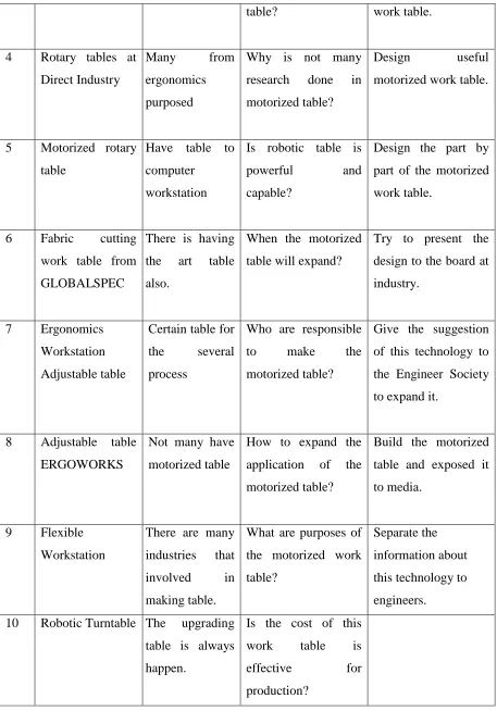
[image:22.612.190.424.161.315.2]2.4.1 Panasonic 3 Axis Model ISP Cartesian Robotic Tig Welding Cell
Figure 2.1 RC505001 "2003" Panasonic 3 Axis Model ISP Cartesian Robotic Tig Welding Cell
There are many examples for the welding table. One of it is RC505001 "2003" Panasonic 3 Axis Model ISP Cartesian Robotic TIG Welding Cell. Initially powered up in November 2003 this cell was used off and on for approximately 8 months before the application was discontinued. This Panasonic Model ISP Cartesian Robot has approx. 43" (x) horizontal movement, 15" (y) vertical movement and 21" (z) horizontal movement. There is also a 2 axis clamping fixture or tooling table. The complete welding package on this cell includes Two (2) Water Cooled TIG Torches with manual adjustable separation of the torch holders on one axis, Two (2) Panasonic YC-500WX4 Power Supplies completely integrated with all regulators, hoses, cables etc. Water supply required. The welding cell is 75" wide x 103" high x 145" deep and has a complete safety package including, Powered Safety Screen, Light Package, Front Operating Control and Palm Buttons. This cell could be changed to the MIG welding process.
Panasonic Model ISP Cartesian Robot has approx. 17 1/2" (x) horizontal movement, 10" (y) vertical movement and 15" (z) horizontal movement. The Fourth Axis is a Rotating Wrist movement for the Torch Holding Device. This Cell also includes a Horizontal Moving Fixture/Tooling Table Integrated with the Robot from the Load/Unload position to the Robotic Welding Position. The Complete Welding Package on this cell includes one (1) Panasonic YC-300WX4 Power Supply and One (1) Water Cooled TIG Torch completely integrated with all cables, hoses, etc. Water supply required. The welding cell is 75" wide x 103" high x 126" deep and has a complete safety package including, Powered Safety Screen, Light Package, Front Operating Control and Palm Buttons. This cell also could be changed to the MIG welding process.
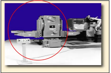
[image:23.612.145.467.362.608.2]2.4.2 Interaction Adjustable Tables by Knoll
Figure 2.3: Interaction Adjustable Tables
2.4.2.1 Manually Adjustable Base
26 ½” to 29 ½” height range, on ½” increments
Legs include integral vertical wire manager
Crossbeam is designed for cable storage, and includes removable black PVC cable flap
Locking casters can be retrofitted, and increase table height range 1 ½.
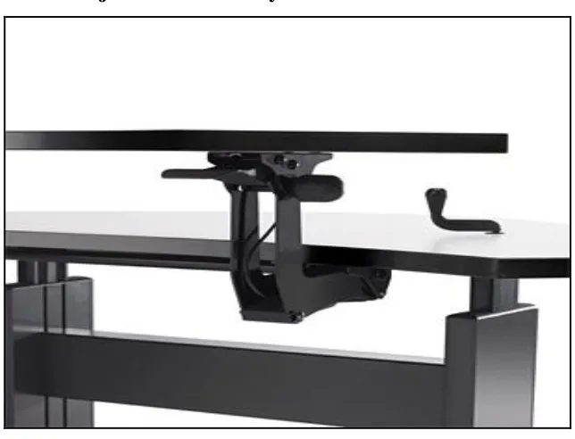
2.4.2.2 Crank Adjustable Table
23 ½” to 35” height adjustment range
300 lb load capacity(not including worksurface)
Five turns of the handle adjust worksurface one inch
Handle folds beneath worksurface when not in use
Legs include integral wire manager
Locking casters can be retrofitted, and increase table height range 1 ½”
2.4.2.3 Counterforce Table
Counterforce provides rapid sit-to-stand adjustment, in 26” to 41” range
Hand paddle actuates the vertical adjustment mechanism
Safety interlock presented inadvertent height change
Legs include integral vertical wire manager
Locking casters can be retrofitted, and increase table height range 1 ½”
2.4.2.4 Top Crank and Electric Height Adjustable Table