“I hereby declared that I have read through this report and found that it has comply the partial fulfillment for awarding the degree of Bachelor of Mechanical
Engineering (Material and Structure)”
Signature : ………
Supervisor’s Name : ………
DESIGN A FEASIBLE CLOTH DRIER UTILIZING DOMESTIC WASTE-HEAT FOR HOUSEHOLD APPLICATION
MUHAMMAD SYIMIR HAZIQ BIN SANSUL BAHRI
This report is submitted to partial fulfillment of term for
Bachelor of Engineering Mechanical (Material and Structure)
Faculty of Mechanical Engineering Universiti Teknikal Malaysia Melaka
“I hereby declared this report is mine except summary and each quotation that I have mentioned the resources”
Signature:……… Author’s Name:………..
iii
iv
ACKNOWLEDGEMENT
I, Muhammad Syimir Haziq, the writer of this report, want to share a big thank you to my supervisor, Puan Fatimah Al-Zahrah Mohd Sa’at and also not forgotten my second evaluator, Mr. Mohamad Firdaus B. Sukri for the support and her guidance to complete this report. This thank you is also dedicated for those who give me morel guidance and advice during the report writing period.
v
ABSTRACT
vi
ABSTRAK
vii TABLE OF CONTENTS
CHAPTER TOPIC PAGE
VERIFICATION ii
DEDICATION iii
ACKNOWLEDGEMENT iv
ABSTRACT v
ABSTRAK vi
TABLE OF CONTENT vii
LIST OF TABLE ix
LIST OF FIGURE x
NOMENCLATURE xi
LIST OF APPENDIX xv
CHAPTER 1 INTRODUCTION 1
1.1Problem Statement 3
1.2 Objective 4
1.3Scope 4
CHAPTER 2 LITERATURES REVIEWS 5
CHAPTER 3 METHODOLOGY 19
3.1 Drying Cabinet Design 19
3.2 Material properties 22
3.3 Structural design 25
3.4 Testing and analysis 27
CHAPTER 4 RESULT AND DISCUSSION 31
4.1 Result 32
4.2 Discussion 44
viii
CHAPTER 5 CONCLUSION 49
REFERENCE 51
BIBLIOGRAPHY 53
ix
LIST OF TABLE
NO TITLE PAGE
3.1 Criteria for 3 design 20
3.2 Importance weight for 3 design 21
3.3 Choosing design using Pahl and Beitz’s Method 21
4.1 Weight of the towel in experiment 1 33
4.2 Mass of the towel before and after the drying process in 38 experiment 2.
4.3 Mass of the towel before and after the drying process in 40 experiment 3.
4.4 List of mass of the towel in all experiments 43
x
LIST OF FIGURE
NO TITLE PAGE
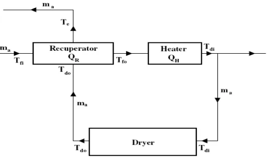
2.1 Diagram of a textile drying system with waste-heat 5 recovery. (Source: R. Tugrul Ogulata, 2004)
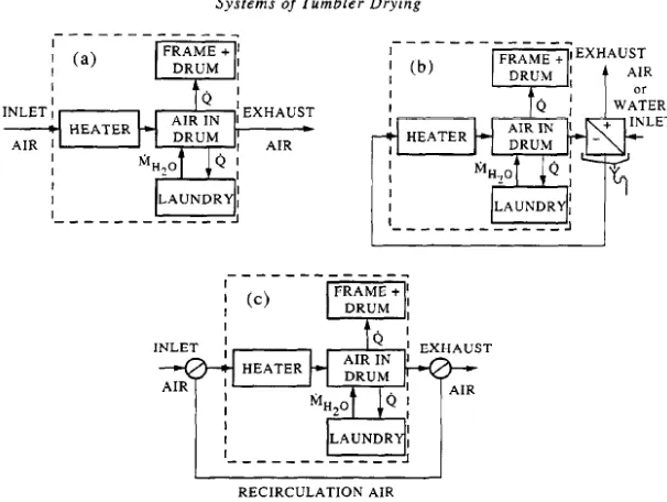
2.2 The various systems of air circulation currently used 7 in tumbler dryers. (S.S. Elsayeda, et al. 2006)
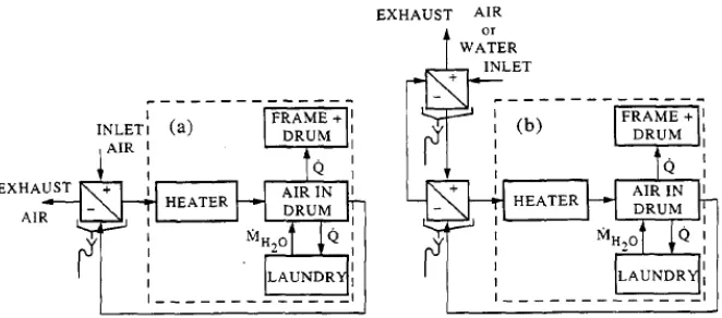
2.3 Schematic representation of the systems proposed for 8 heat recovery in tumbler dryers: (a) Openloop system;
(b) Closed-loop system. (S.S. Elsayeda, et al. 2006)
2.4 Schematics of a conventional air-vented dryer. 9 (V. Yadav, 2007)
.
2.5 Simple refrigeration system (Source : Wikipedia) 16
2.6 Simple of RAC systems (J.E Braun, 2001) 16
3.1 View Drawings for 3 proposes design 19
3.2 Schematics of the laboratory experimental rig 25 and the sensor position. (Source: Shiming Deng, 2004)
xi
3.4 8 Channel Pico Log Data Logger 28
3.5 Thermometer-Humidity Sensor 28
3.6 Weight balance that used in this experiment 29
3.7 Flow chart of the design of drying cabinet 29
4.1 The towel as specimen for three experiments 32
4.2 Experiment apparatus 33
4.3 Point of thermocouple in cabinet dryer 34
4.4 Graph temperature (oC) versus time (minute) for 35
towel dryer process
4.5 Graph Humidity (%Rh) versus Time (minute) for 36 towel dryer process
4.6 Superimpose graph of Temperature (oC) and Humidity 37 (%Rh) against Time (minutes) for experiment 1.
Ta (0-40 minutes), Tb (40-80 minutes)
and Tc (80-120 minutes)
4.7 Graph Temperature (oC) against Time (minute) 38 for experiment 2
xii 4.9 Superimpose graph of Temperature (oC) and 39
Humidity (%Rh) against Time (minutes) For experiment 2. Ta (0-50 minutes), Tb (50-100 minutes)
and Tc (100-200 minutes)
4.10 Graph Temperature (oC) against Time (minutes) 41 for experiment 3
4.11 Graph Humidity (%Rh) against Time (minutes) 41 for experiment 3
4.12 Superimpose graph of Temperature (oC) and 42
Humidity (%Rh) against Time (minutes). Ta (0-100 minutes), Tb (100-200 minutes)
and Tc (200-250 minutes)
4.13 The similarity for A. Amin’s model 45
(a) and S. Deng’s model (b). Both models was directed from the condenser to the drying place
4.14 The flexible hose 46
4.15 Side view for recommendation model 47
xiii
NOMENCLATURE
Cp specific heat capacity (kJ/kg K)
Es energy-saving rate (%)
k drying rate (%)
ma rate of process air (kg/h)
me rate of evaporated water (kg/h)
mpi rate of product-input to dryer (kg)
mpo rate of product-out from dryer (kg)
Q actual heat-transfer (kJ)
QH heater capacity (kJ/h)
Qmax maximum possible heat-transfer (kJ)
QR heat of recuperator (kJ/h)
QT total heat rate (kJ/h)
t drying time (h)
Ta ambient-air temperature (0C)
Tdi dryer-inlet air temperature (0C)
Tdo dryer-outlet air temperature (0C)
Te exhaust-air temperature (0C)
Tfi recuperator-inlet air (fresh-air) temperature (0C)
Tfo recuperator-outlet air (fresh-air) temperature (0C)
X1 dryer-inlet air_s moisture-content (kgw/kga) X2 dryer-outlet air_s moisture-content (kgw/kga)
∆X difference of dryer inlet–outlet moisture content (kgw/kga) ∆T difference between Tdo and Te (0C)
ε effectiveness of heat recuperator (%)
φ ambient-air_s relative humidity (%)
Cp specific heat (kJ/kg K)
xiv
MBD bone-dry mass of clothes (kg)
Q heat-flow rate (kW)
Tm mean temperature of the clothes (0C) X moisture content of clothes
ω specific humidity
Subscripts
a air
cold cold fluid hot hot fluid max maximum min minimum w water a air
BD bone-dry mass cl clothes
D drum evap evaporation
0 ambient
xv
LIST OF APPENDIX
NO TITLE PAGE
A 3 types of drawing 53
B Properties of three materials 57
C Tables for three experiment temperature 63
D Humidity table for 2 hour, 3 hour and 4 hour respectively 66
1
CHAPTER I
INTRODUCTION
In large densely populated cities, residential buildings are usually high-rise blocks. In order to maintain an acceptable appearance of building façade, clothes drying using natural means by hanging clothes outside windows or a balcony may not be allowed. Increasingly, a clothes drying has become confined to indoors, either at the expense of consuming energy through the use of clothes dryers or by natural ventilation. Clothes drying indoors using natural ventilation, versus by an electrical or a gas clothes dryer, can take days, depending on textile type, weather conditions, and the location of a residential flat in a high-rise residential block (e.g., prevailing flat orientation and floor level). In places where air humidity is high (wet seasons or during rainy days), clothes drying indoors by natural ventilation can take a long time and still yield unsatisfactory results. In addition, drying clothes indoors by natural ventilation has an effect on the indoor thermal environment, as the moisture contained in wet clothes is transferred to internal ventilation during drying, by evaporation and diffusion. This additional excess moisture must be dealt with through either mechanical or natural ventilation means. Besides using cloth dryer and air condition leads to global warming.
2
in 2005. The Intergovernmental Panel on Climate Change (IPCC) state that most of the observed increase in globally averaged temperatures since the mid-twentieth century is very likely due to the observed increase in anthropogenic (man-made) greenhouse gas concentrations via an enhanced greenhouse effect. Natural phenomena such as solar variation combined with volcanoes probably had a small warming effect from pre-industrial times to 1950 and a small cooling effect from 1950 onward.
Climate model projections summarized by the IPCC indicate that average global surface temperature will likely rise a further 1.1 to 6.4 °C (2.0 to 11.5 °F) during the twenty-first century. This range of values results from the use of differing scenarios of future greenhouse gas emissions as well as models with differing climate sensitivity. Although most studies focus on the period up to 2100, warming and sea level rise are expected to continue for more than a thousand years even if greenhouse gas levels are stabilized. The delay in reaching equilibrium is a result of the large heat capacity of the oceans.
Increasing global temperature is expected to cause sea levels to rise, an increase in the intensity of extreme weather events, and significant changes to the amount and pattern of precipitation, likely leading to an expanse of tropical areas and increased pace of desertification. Other expected effects of global warming include changes in agricultural yields, modifications of trade routes, glacier retreat, mass species extinctions and increases in the ranges of disease vectors.
Some of the disasters are sea level increasing, extreme weather, agricultural yields and most worst, species extinction. Therefore, we must avoid it before its getting worse. To avoid it, we must know the cause of the global warming.
3
condition and air condition. We can save this world from disaster if we can reuse or at least reduce the dangerous element from “eating up” the ozone.
This is the main idea for this study of utilize waste heat from air condition that reuses the heat that been rejected to use for another activity. For this current study, it is to make the idea feasible of drying cloth using the heat exhausted from the air condition.
With using back the waste heat, it can make some benefits. For some example that relate to this study, RAC air condition is one of home applicant that we never turn off. Thus, its better we use the heat that exhausted to dry washed cloth over time rather let the waste heat being wasted. On the same time we can save time and also money rather buying cloth dryer that cost so much.
The concept of the RAC system for clothes drying had been pioneered by R. Tugrul Ogulata in 2004 and patented by Shiming Deng in 2004 with the wooden prototype but in this study focuses on an experimental study on the effectiveness of clothes drying using rejected heat (CDURH) with a split-type RAC which will make some improvisations based on mechanical formula hopefully to be a successful method.
1.1 Problem Statement
4
1.2 Objective
To design a system that can utilize waste heat from an air condition to a feasible cloth drying apparatus for house hold application utilizing waste heat. Also, it is to analyze the performance or efficiency of the design.
1.3 Scope
5
CHAPTER II
LITERATURE REVIEW
[image:21.612.193.468.412.577.2]Drying is one of thousand activities that we done daily. The drying process were normally using sun ray to reduce the cloth humidity. But in the area is humid which is limited sun rays and restrict air flow, using a tumble dryer is the right choice (A. Ameen et. Al 2004). Another method is heat pump dryer which is not so well known to people.
Fig 2.1: Diagram of a textile drying system with waste-heat recovery. (Source: R. Tugrul Ogulata, 2004)
6
of residential using electricity in the US is from cloth dryers. (V. Yadav et. Al 2007). Another type of tumble dryer is evaporative tumble dryer that generates hot air steam up to 50o-70oC used to dry clothes and discharged into outdoors as air pollution and local heat.
To solve this problem, people try to use a heat pump tumble dryer which use waste heat to remove moister. For this kind of tumble dryer, there no are commercial efforts yet because it’s under research. There are many designs that use different way. The following figure shows that a drying systems that studied by R.Tugral Ogulata 2004. The figure shows that the humid and dirty waste air is sent to heat exchanger. The fresh air from environment and the waste air were realized by heat transfer via pale type heat exchanger (cross flow) the waste air passes through the abutting channel. This make the fresh air temperature is raised and cooled waste air and sent to ambient environment. The temperature of the preheated fresh air is future raised in air heater. (R.Tugral Ogulata 2004)
7
Fig 2.2: The various systems of air circulation currently used in tumbler dryers (S.S. Elsayeda, et al. 2006)
recirculation lowers the driving force for the evaporation of the water from the textile. This also applies to condensation tumblers as in Fig. 2(b), where the exhaust air is cooled by ambient air. (Manuel R Conde et. Al, 1997)
(1)
(2)
The equations 1 and 2 show, all other conditions being equal, that the lower the partial pressure of water vapour in the drying air pp.a, the faster the drying process will
8
[image:24.612.162.493.279.425.2]humidity content of the air should be kept as low as possible. This is not the case both in the system with recirculation and in that with humidity condensation by cooling with ambient air. It is eventually possible by condensing with cold water or by forcing the humid air across the evaporator of a heat pump. Figure 2.3 shows schematically the solutions proposed for open and closeloop systems. For household applications, where the disposal of humidity inside the laundry room may create problems with the building structure, the close-loop system seems the logical response, though the potential for energy recovery should still be interesting with a system as that depicted in Fig. 2.3(b).
Fig 2.3: Schematic representation of the systems proposed for heat recovery in tumbler dryers: (a) Openloop system; (b) Closed-loop system.
(S.S. Elsayeda, et al. 2006)