AUTOMATIC WATER LEVEL CONTROL
RAHAYU BINTI ABD RAHMAN
This Report Is Submitted in Partial Fulfillment of the Requirements for the award of Bachelor of Electronic Engineering (Industrial Electronic) With Honours
Faculty of Electronic Engineering and Computer Engineering Universiti Teknikal Malaysia Melaka
UNIVERSTI TEKNIKAL MALAYSIA MELAKA
FAKULTI KEJURUTERAAN ELEKTRONIK DAN KEJURUTERAAN KOMPUTER
BORANG PENGESAHAN STATUS LAPORAN
PROJEK SARJANA MUDA II
Tajuk Projek : AUTOMATIC WATER LEVEL CONTROL Sesi
Pengajian : 2008/09
Saya ………....RAHAYU BINTI ABD RAHMAN………..……..
(HURUF BESAR)
mengaku membenarkan Laporan Projek Sarjana Muda ini disimpan di Perpustakaan dengan syarat-syarat kegunaan seperti berikut:
1. Laporan adalah hakmilik Universiti Teknikal Malaysia Melaka.
2. Perpustakaan dibenarkan membuat salinan untuk tujuan pengajian sahaja.
3. Perpustakaan dibenarkan membuat salinan laporan ini sebagai bahan pertukaran antara institusi pengajian tinggi.
4. Sila tandakan ( √ ) :
SULIT*
(Mengandungi maklumat yang berdarjah keselamatan atau kepentingan Malaysia seperti yang termaktub di dalam AKTA RAHSIA RASMI 1972)
TERHAD* (Mengandungi maklumat terhad yang telah ditentukan oleh
organisasi/badan di mana penyelidikan dijalankan)
TIDAK TERHAD
Disahkan oleh:
__________________________ ___________________________________
(TANDATANGAN PENULIS) (COP DAN TANDATANGAN PENYELIA)
Alamat :1176,Kg Durian Burung,
20050 Kuala Terengganu,
Terengganu.
Tarikh: 30 April 2009 Tarikh:
―I declared that this thesis is the result of my own work except the ideas and summaries which I have clarified their sources.‖
Signature : ………
Writer : Rahayu Binti Abd Rahman
―I hereby declare that I have read this report and in my opinion this report is sufficient in terms of the scope and quality for the award of Bachelor of Electronic Engineering (Industrial Electronic) With Honours‖
Signature : ………
Supervisor’s Name : En Chairulsyah bin Abdul Wasli
DEDICATION
My parents Abd Rahman bin Ismail, Salmah Binti Lateh and my brothers and sisters
(aya, ain, atah, amira, amin & aqim) who has encouraged, guided and inspired me
ACKNOWLEDGEMENT
First of all, I would like to thank Almighty Allah for His blessing and His power for me to complete this Project Sarjana Muda.
I would like to take this opportunity to express my deepest gratitude to my project supervisor En Chairulsyah Abdul Wasli who has persistently and determinedly assisted me during the whole course of this project. It would have been very difficult to complete this project without the enthusiastic support, insight and advice given by him.
My outmost thanks also go to my family who has given me support throughout my academic years. I would like to thanks them for understanding and always giving me courage and the strength I need to carry on this project. Without them, I might be not being the person I am today.
ABSTRACT
Automatic Water Level Control is a project that has been purpose to maintain
ABSTRAK
“Automatic Water Level Control‖ adalah satu projek yang diusulkan untuk
menseimbangkan air pada satu tahap tertentu. Projek ini menggunakan dua penggerak iaitu pam dan injap. Pam berfungsi memasukkan air dalam tangki dan injap berfungsi untuk mengawal keluar masuk air. Apabila air tinggi daripada tahap yang ditetapkan, maka injap akan berfungsi untuk mengeluarkan air sehingga tahap yang ditetapkan dan apabila air rendah daripada tahap yang ditetapkan, maka injap akan tertutup dan pam akan berfungsi untuk memasukkan air kedalam tangki sehingga mencapai tahap yang ditetapkan. Projek ini menggunakan PLC (Programmable Logic Controller) untuk mengawal air keluar masuk dan bila sepatutnya pam berfungsi. Perisian CX-programmer digunakan untuk membuat ladder diagram. Macromedia Flash 8 juga turut dibuat untuk menghasilkan animasi
TABLE OF CONTENT
CHAPTER TITLE PAGE
PROJECT TITLE i
STATUS DECLARATION FORM ii
DECLARATION iii
DEDICATION v
ACKNOWLEDGEMENT vi
ABSTRACT vii
ABSTRAK viii
TABLE OF CONTENTS ix
LIST OF TABLES xiii
LIST OF FIGURES xiv
LIST OF APPENDIX
I PROJECT OVERVIEW 1
1.1 Project Overview 1
1.2 Project Objectives 3
1.3 Scope of Work 2
1.4 Problem Statement 4
1.5 Methodology 4
1.6 Thesis Outlines 5
2.1 Background Study 6
2.2 Control Theory 7
2.2.1 Open Loop and Closed Loop System 8
2.2.2 Application for Feedback System 10
2.2.3 Advantages of Feedback Control 10
2.2.4 Costs of feedback Control 11
2.2.5 Stability of closed-loop systems 12 2.2.6 Design
2.3 Programmable Logic Controller 13
2.3.1 Introduction 14
2.3.2 Programming Language 15
2.3.3 PLC Connections 20
2.3.4 Ladder Logic Input 22
2.3.5 Ladder Logic Output 23
2.3.6 Function Block Diagram (FBD) 24
2.4 Hardware 24
2.4.1 Solenoid Valve 24
2.4.2 Submersible Pump 27
2.4.3 Float Sensor 29
2.4.4 Relay 35
2.4.5 Seven Segment Display 40
III METHODOLOGY 43
3.1 Project Methodology 43
3.2 Methodology Flow chart 44
3.2.1 The Literature 45
3.2.2 Theory of The Calculation 50
3.2.3 Animation 53
3.2.5 PLC program 57
3.2.6 Hardware Development 61
IV RESULTS AND DISCUSSIONS
4.1 Animation result 63
4.1.1 To Reach Medium Level 64
4.1.2 To Decrease from High level to Medium Level 64 4.1.3 To Increase from Low level to Medium Level 65
4.2 Calculation Result 67
4.3 Measurement Results 68
4.3.1 Comparison 69
4.4 Discussions 70
4.4.1 From Empty Tank to Medium Level 70 4.4.2 From High Level to Medium Level 70
4.4.3 From Low to Medium Level 71
4.5 CX Programmer 72
4.6 Mnemonics Code 73
4.6.1 Ladder diagram Inputs and Outputs 74
4.7 Hardware Results 75
V CONCLUSIONS 78
5.2 Conclusion 80
5.3 Suggestions 80
REFERENCES 81
LIST OF TABLE
NO TITLE PAGE
2.1 The Reference T thesis from the previous year 7
2.2 Specification of float sensor 33
2.3 Configuration of Relay 38
3.1 Table of velocity 50
3.2 Time Taken According to Condition 53
3.3 Main Address 59
4.1 The calculation results 67
4.2 The Measurement Results 68
4.3 Comparison between Calculations and Measurement results 69
4.4 Address for Inputs 74
LIST OF FIGURE
NO TITLE PAGE
1.1 The Automatic Water Level Control 2
2.1 Open Loop Systems 9
2.2 Closed Loop Systems 9
2.3 PLC Connections 14
2.4 Ladder diagram 15
2.5 Simple of Ladder Logic 16
2.6 Simple Relay Layouts and Schematic 18
2.7 A Simple Relay Controller 19
2.8 A PLC illustrated with Relays 20
2.9 The Separation of Controller and Process 21
2.10 The Scan Cycle of PLC 22
2.11 Ladder Logic Inputs 22
2.12 Ladder Logic Outputs 23
2.13 Solenoid Valve 25
2.14 The Solenoid Parker Valve 25
2.15 The Position of valve at the storage tank 26
2.16 Submersible pump 27
2.17 The Aquarium Motor 28
2.18 The Pump in the Water Supply Tank 28
2.20 Vertical float switch 31
2.21 Schematic of float switch sensor 32
2.22 Float sensor 33
2.23 The view of float sensor in the storage tank side 34
2.24 The Level of Each Sensor 35
2.25 Relay 36
2.26 Circuit symbols of relay 38
2.27 The Omron Relay 39
2.28 The Connection of the relay in the project 39
2.29 Seven Segment Display 41
2.30 Seven segment display high 42
2.31 Seven segment display medium 42
2.32 Seven segment display low 42
3.1 Flow Chart of Methodology 45
3.2 One-dimensional duct showing control volume 46
3.3 Bernoulli Equation 46
3.4 Illustration inside the nozzle flow meter 50
3.5 Calculation Model 50
3.6 Design of Hardware 55
3.7 PLC Ladder Diagram 57
3.8 Mneumonic Code 58
3.9 Address at the input 60
3.10 Address at the output 60
3.11 The full set of automatic water level control 61
4.1 From empty tank to the medium level 64
4.2 From high level to medium level 64
4.3 From low level to medium level 65
4.4 Design of animation at initial condition 66
4.5 Block Diagram from empty tank to the medium level 70
4.6 Block Diagram From high level to medium level 70
4.7 Block Diagram From low level to high level 71
4.9 Mneumonic Code 73
4.10 The model of the project 75
4.11 Indicator lamp 76
4.12 Seven Segment Display 76
4.13 Connection Input and Output to the PLC 77
CHAPTER I
INTRODUCTION
Water is very important to human being. The management of water is very important to avoid it wasted. The Automatic Water Level Control is introduced to help the human being to manage the water in their life.
1.1 Project Overview
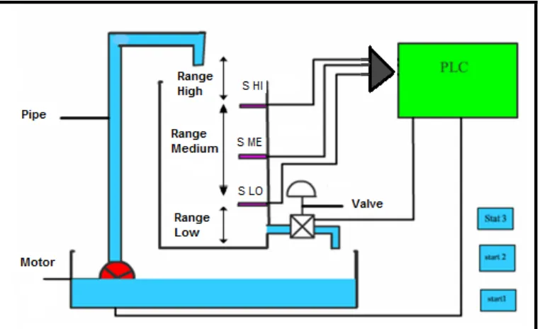
Automatic Water Level Control was used for on/off signal. The system is very useful
to the house and the factory. The purpose of this project is to keep the water at the certain level. The water is set at three level which is high level, medium level and low level. The purpose of this project actually to keep the water stable at the medium level
But if there are any disturbances occurred, such as the water at the high level the water will decrease and stop at the medium level. Then when the water at low level, the pump will on and pump the water until it reaches the medium level. Then the pump will off. In this operation, when the manual valve is on, the pump will on until it the medium sensor is on. The seven segments will display low when the
pump is on. When the high level sensor on, the seven segment will display high but the seven segment will display
medium when the level of the water is higher than the low sensor and below the high sensor.
In this project, the types of system involve components such as process water holding tanks, actuators as valves and pumps and measured values as level, flow and composition. The flow of water into the tank is controlled by a valve. The control input signal to the valve is a current signal in mA which is converted into a pressure signal.
[image:18.595.116.497.484.716.2]This pressure is applied to a valve and changes the valve stem position in mm. the valve position dictates the amount of flow passing through the valve into the tank. The height of water in the tank is measured by a transducer (gauge pressure) which produces an output in mA.
1.2 Objective
In order for the project to success and to be implemented, the following objectives have to be achieved:-
1) To design and develop an automatic water level control using PLC
2) To learn about the Macromedia Flash Software this can display the anime of the increasing or decreasing of the water in the tank.
3) To learn more about the characteristic of the sensor and others devices such as valve and motor
1.3 Scopes Of work
The scopes of works in this project are:
1) In this project the control system should be study to control the outflow of the water. The specification of the float sensor also must be study to use as a sensor.
2) In order to make this project successful, ladder diagram must be built using CX programmer.
3) After the theoretical, the development of PLC and the hardware will continue and be tested
1.4 Problem Statement
The traditional water tank had many disadvantages such as:
1) Traditional water level must draw the water manually to the tank when there is no water in the tank.
2) The problem of manual control is sometimes people forget to turn off or turn on the valve.
3) For the automatic water level control, if the manual float broken or damage, all the system can’t function properly.
4) To avoid the overfilling of the open container in industrial
1.5 Methodology
There are a few methods that must be following to complete this project. The method is as below:
1) The project had started with study the literature of the project. It’s including the operation of the project and the purpose of the project.
2) Then, it will continue to research about the calculation of the water flow including the water level, volume, velocity and the time its take to fill in the tanks and drain the tanks. The calculation should be including the area of the pipe and nozzle and the it should be affected by the gravity.
3) If the formula related enough, then can proceed to the animation. To create the animation, the Macromedia flash 8 had to study first. Then can create the water draws in the tank and the water decreasing when there are some disturbances. But if the formula does not enough, then the literature reviews need to be study again.
5) Test the functionality of the ladder diagrams and the hardware. Then integrate the hardware and the software. If it can’t function, then try to construct the ladder diagram and the hardware again.
6) Then if the hardware and software is successfully done, then prepare for the final report and submit to the supervisor.
1.6 Thesis Outline
This thesis will be divided into 5 chapters to provide the understanding of the whole project.
Chapter 1 is introduction to the overview of this project and its objectives. It
also explains the scopes of the project.
Chapter 2 describe about the literature review that has been studied to get
information to complete the project. This study is focused especially on automatic level control.
Chapter3 covers up all the project methodology and a process this project implementation to achieve goal. Also hardware and software technical details are explained in this part.
Chapter 4 explains the results and discussions of the project and what had
been done in the whole semester.
CHAPTER II
LITERATURE REVIEW
For complete this report, a few reference had been made. There are a few theses that had been referred as a literature review. The past year thesis that related with this title is the past year theses from the Faculty of Electric Engineering.
2.1 Background Study
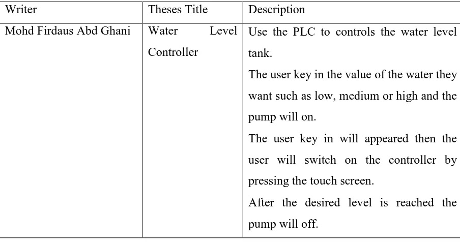
Table 2.1 The Reference Thesis from the previous year.
Writer Theses Title Description
Mohd Firdaus Abd Ghani Water Level Controller
Use the PLC to controls the water level tank.
The user key in the value of the water they want such as low, medium or high and the pump will on.
The user key in will appeared then the user will switch on the controller by pressing the touch screen.
After the desired level is reached the pump will off.
2.2 Control Theory
Control theory is an interdisciplinary branch of engineering and mathematics, that deals with the behavior of dynamical systems. The desired output of a system is called the reference. When one or more output variables of a system need to follow a certain reference over time, a controller manipulates the inputs to a system to obtain the desired effect on the output of the system. [11]
In a closed-loop control system, a sensor monitors the output (the vehicle's speed) and feeds the data to a computer which continuously adjusts the control input (the throttle) as necessary to keep the control error to a minimum (to maintain the desired speed). Feedback on how the system is actually performing allows the controller (vehicle's on board computer) to dynamically compensate for disturbances to the system, such as changes in slope of the ground or wind speed. An ideal
Interconnections of components forming system configurations which will provide a desired system response as time progresses. The steering of an automobile is a familiar example. The driver observes the position of the car relative to the desired location and makes corrections by turning the steering wheel. The car responds by changing direction and the driver attempts to decrease the error between the desired and actual course of travel. In this case, the controlled output is the automobile's direction of travel, and the control system includes the driver, the automobile, and the road surface.
The control engineer attempts to design a steering control mechanism which will provide a desired response for the automobile's direction control. Different steering
designs and automobile designs result in rapid responses, as in the case of sports cars, or relatively slow and comfortable responses, as in the case of large autos with power steering.
2.2.1 Open Loop and Closed Loop Control Systems
The basis for analysis of a control system is the foundation provided by linear system theory, which assumes a cause-effect relationship for the components of a system. A component or process to be controlled can be represented by a block. Each block possesses an input (cause) and output (effect). The input-output relation