ePrints Soton
Copyright © and Moral Rights for this thesis are retained by the author and/or other
copyright owners. A copy can be downloaded for personal non-commercial
research or study, without prior permission or charge. This thesis cannot be
reproduced or quoted extensively from without first obtaining permission in writing
from the copyright holder/s. The content must not be changed in any way or sold
commercially in any format or medium without the formal permission of the
copyright holders.
When referring to this work, full bibliographic details including the author, title,
awarding institution and date of the thesis must be given e.g.
FACULTY OF ENGINEERING, SCIENCE & MATHEMATICS
OPTOELECTRONICS RESEARCH CENTRE
Power Scaling of Laser Oscillators
and Amplifiers Based on Nd:YVO
4
Michael James Yarrow
Thesis submitted for the degree of Doctor of Philosophy
FACULTY OF ENGINEERING, SCIENCE AND MATHEMATICS OPTOELECTRONICS RESEARCH CENTRE
Doctor of Philosophy
POWER SCALING OF LASER OSCILLATORS AND AMPLIFIERS BASED
ON Nd:YVO4
By Michael James Yarrow
This thesis presents a strategy for power and brightness scaling in diode-end-pumped, master-oscillator-power-amplifier laser systems, based on Nd:YVO4, to achieve
mode-locked and single-frequency output powers up to∼80W with minimal degradation in beam quality due to thermal effects.
Scaling output powers to the tens of watts regime in diode-end-pumped solid-state oscillators and amplifiers, without causing severe degradation in beam quality, is chal-lenging because the large thermal loading density and large thermal gradients in end-pumped gain media cause a number of undesirable thermal effects. In Nd:YVO4, these
thermal effects are particularly severe due to its relatively poor thermal and mechan-ical properties, however its attractive spectroscopic properties make power scaling of Nd:YVO4 laser sources an area of much interest.
An actively mode-locked, diode-end-pumped, Nd:YVO4oscillator was constructed
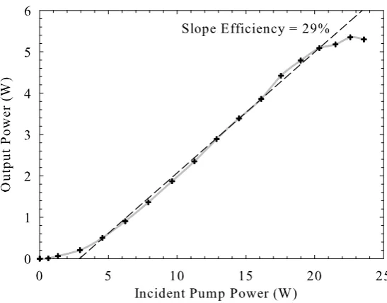
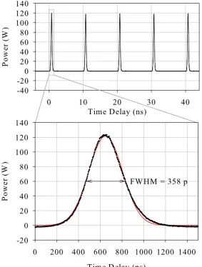
which produced 360ps pulses at 100MHz repetition rate and an average power of up to 5.3W for 22W of pump power. This source was used to seed a diode-end-pumped, Nd:YVO4 amplifier chain which was optimised, with the aid of theoretical models, to
achieve high gain, high efficiency and low degradation in beam quality. The amplifier yielded a small signal gain of∼7000 and a maximum output power of 94W for 237W of absorbed pump power. The M2 values at 79W output power were measured to be 1.7 and 1.9 in orthogonal planes. The amplifier was also operated in long-pulse-train mode by using an acousto-optic modulator to gate the input, thereby achieving higher gains and higher peak powers. In this regime, up to ∼400kW peak powers could be achieved and, by pulse shaping of the seed laser, pulse trains as long as 1µs were achieved with∼30kW peak powers and>10W average power.
A single-frequency diode-end-pumped Nd:YVO4 oscillator was also used to seed
the amplifier chain. In cw mode, this produced up to 79W of mode-hop-free, single-frequency output withM2values of 1.48 and 1.43 in orthogonal planes. Pulse shaping techniques provided output powers of 1kW for long, 1µs , pulses of rectangular shape with∼10W of average power.
In pulsed (high gain) mode of operation, the beam quality of the two sources was found to be improved significantly due to the effect of gain-guiding in the amplifier.
I,Michael James Yarrow, declare that this thesis entitledPower Scaling of Laser Oscillators and Amplifiers based on Nd:YVO4 and the work presented in it are
my own. I confirm that:
• this work was done wholly while in candidature for a Research degree at the University of Southampton;
• where any part of this thesis has been previously submitted for a degree or any other qualification at this University or any other institution, this has been clearly stated;
• where I have consulted the published work of others, this is always clearly attributed;
• where I have quoted from the work of others; the source is always given. With the exception of such quotations, this thesis is entirely my own work;
• I have acknowledged all main sources of help;
• The derivation of small signal gain in the presence of ETU and setting up of some of the experimental apparatus was based on work done by Dr Ian Musgrave. Chapter 6 of this thesis is based on work done by myself jointly with Dr Ji Won Kim. The single-frequency oscillator in Chapter 6 was built by Dr Ji Won Kim. The rest of this thesis is based on work done wholly by myself;
• parts of this work have been published (see Appendix I for details).
I’d like to thank all those who’ve helped me directly and indirectly over the last few years. First of all, thanks to my supervisor Andy Clarkson for his endless optimism and for bringing everything into focus. Thanks to Ian Musgrave for his time and patience showing me the ropes in the early days and Tim Kendall and Dave Hillier for their tips which probably saved me weeks. Thanks very much to Ji Won Kim for getting things moving in the lab when it really mat-tered. Thanks to all in the ASSL group for their kindness and support. Thanks to Simon, Tim and Chris for making all the gubbins and keeping the lab in ser-vice, the network guys for keeping my work safe and Eve and all the admin. staff for keeping the ORC running smoothly. For useful discussions I’d like to thank Pascal Dupriez. For slightly less useful discussions and distractions, thanks to all my office mates over the years from the legendary P2071 office to the original Portacabin-crew and finally the Portavillage-people. For always be-ing up for a pint, I’d like to thank Ian, Andy, Steve, Jeff, Gates, Hannah, Corin and Stu (amongst many others) and thanks to my old old mates for not giving a monkey’s about lasers. Thanks also to Micha¨el and the paragliding club for keeping my feet firmly off the ground. For their great support, thanks to my Mum, Dad and family. Finally, thank you Catherine for always being right there beside me.
Abstract i
Author’s Declaration ii
Acknowledgements iii
Contents v
Frequently Used Symbols ix
1 Introduction 1
1.1 General Introduction . . . 1
1.2 Background . . . 3
1.3 Thesis Overview . . . 6
1.4 References . . . 10
2 Power Scaling in Solid-State Lasers and Amplifiers 14 2.1 Introduction . . . 14
2.2 The Solid-State Laser . . . 15
2.2.1 The Four-Level Laser Scheme . . . 15
2.2.2 The Laser Oscillator . . . 16
2.2.3 Threshold and Slope Efficiency . . . 18
2.2.4 Laser Amplifiers . . . 18
2.2.5 TheM2 Parameter . . . 20
2.3 Heat Deposition in the Gain Medium . . . 21
2.3.1 The Quantum Defect . . . 22
2.3.2 Lifetime Quenching . . . 22
2.3.2.1 Energy-Transfer-Upconversion . . . 23
2.3.2.2 Excited State Absorption . . . 24
2.5.1 Thermal Stress Induced Birefringence . . . 29
2.5.2 Aberrated Thermal Lensing . . . 31
2.5.3 Thermally-Induced Stress Fracture . . . 32
2.6 Tackling Thermal Effects . . . 32
2.6.1 Laser Architecture Alternatives . . . 33
2.6.1.1 Side-Pumped Slab Lasers . . . 33
2.6.1.2 End-Pumped Rod Lasers . . . 35
2.6.1.3 Thin-Disc Lasers . . . 36
2.6.1.4 Fiber Lasers . . . 37
2.6.2 Phase Conjugation . . . 38
2.7 Diode Pump Sources . . . 39
2.7.1 High Power Diode Bars . . . 39
2.7.2 Diode Stacks . . . 40
2.7.3 Beam Combining and Shaping Techniques . . . 41
2.7.3.1 Microlenses and Microlens Arrays . . . 41
2.7.3.2 Polarisation Combining . . . 41
2.7.3.3 Fibre-Bundle Beam Shaping . . . 42
2.7.3.4 The Two-Mirror Beam-Shaper . . . 43
2.7.4 Fiber Coupling Diode Bars and Stacks . . . 45
2.8 Summary . . . 46
2.9 References . . . 47
3 Development of a Mode-Locked Nd:YVO4 Oscillator 50 3.1 Introduction . . . 50
3.2 Oscillator Design Considerations . . . 52
3.2.1 Influence of Nd3+Doping Concentration . . . . 52
3.2.2 Pumping Scheme . . . 53
3.2.3 Mode-Locking . . . 55
3.3 Resonator Modelling . . . 58
3.4 Mode-locked Oscillator Design . . . 60
3.5 Experimental Results . . . 65
3.6 Summary . . . 71
4.2 Single-Pass Amplifier Theory . . . 76
4.2.1 Small Signal Gain . . . 76
4.2.1.1 The Importance of Pump Beam Profile andM2 77 4.2.1.2 Dependence of Small Signal Gain on Pump and Signal Beam Sizes . . . 79
4.2.2 Effect of Energy Transfer Upconversion . . . 81
4.2.3 Continuous-Wave Saturated Gain Operation . . . 84
4.2.4 Pulse Amplification . . . 87
4.2.5 Maximum Power Optimisation of Signal-Pump Overlap 93 4.3 Aberrated Thermal Lensing . . . 96
4.4 Scaling Output Brightness . . . 101
4.5 Multiple-Rod and Multiple-Pass Amplification . . . 103
4.5.1 Multiple-Pass Amplification . . . 103
4.5.2 Multiple-Stage Amplification . . . 106
4.6 Summary . . . 110
4.7 References . . . 113
5 Realising a High Power Mode-Locked Nd:YVO4 MOPA System 116 5.1 Introduction . . . 116
5.2 Amplifier Design Considerations . . . 118
5.2.1 Thermal Management . . . 118
5.2.2 Relay-Imaging . . . 122
5.2.3 Feedback and Parasitic Lasing . . . 127
5.2.4 Amplified Spontaneous Emission . . . 129
5.3 Multiple-Stage Nd:YVO4 Amplifier Design . . . 131
5.3.1 Pumping Schemes . . . 131
5.3.1.1 Four-Fiber Coupled Diode Stack . . . 131
5.3.2 Double-Rod Geometry . . . 135
5.3.3 Optimising Signal-Pump Overlap . . . 136
5.3.4 Three Stage Amplifier . . . 140
5.4 Continuous Wave Operation of Amplifier Chain . . . 144
5.5 Influence of Gain-Guiding on Beam Quality . . . 153
5.7.2 Peak Power and Average Power Results . . . 161
5.7.2.1 Varying Pulse Repetition Rate . . . 161
5.7.2.2 Varying Pulse Width . . . 164
5.7.2.3 A 1µs Pulse Envelope, 10kHz, Mode-Locked Source165 5.8 Summary . . . 167
5.9 References . . . 170
6 A Nd:YVO4MOPA as a High-Power Single-Frequency Source 173 6.1 Introduction . . . 173
6.2 Single-Frequency Lasers . . . 176
6.2.1 Achieving Single-Frequency Oscillation . . . 177
6.2.2 Mode-Hopping Suppression . . . 178
6.3 Single-Frequency Master-Oscillator . . . 180
6.3.1 Single-Frequency Oscillator Performance . . . 181
6.4 Single-Frequency Amplification . . . 183
6.4.1 Single-Frequency cw Operation of the MOPA System . . 185
6.4.2 Pulsed Operation of the MOPA System . . . 186
6.5 Pulse Shaping Techniques . . . 191
6.5.1 Mode-Locked MOPA Pulse Shaping . . . 193
6.6 Summary . . . 195
6.7 References . . . 196
7 Conclusions and Future Directions 200 7.1 Summary of Thesis . . . 200
7.1.1 Nd:YVO4 Master-Oscillator . . . 200
7.1.2 Mode-locked MOPA system . . . 201
7.1.3 Single-Frequency MOPA system . . . 203
7.2 Future Directions . . . 204
7.2.1 Further Characterisation . . . 204
7.2.2 Further Power Scaling . . . 205
7.2.3 Non-linear Frequency Conversion . . . 208
7.2.4 A Synchronously-Pumped OPO . . . 210
7.2.5 A Single-Frequency cw or Quasi-cw SRO . . . 211
C Dealing with Errors 219
c Speed of light in vacuum [2.998×10⁸ms−1]
h Planck constant [6.626×10⁻³⁴Js]
lc Cavity length [mm]
lg Length of gain medium [mm]
σ21 Stimulated emission cross section [m2]
τf Fluorescence lifetime [µs ]
αp Absorption coefficient at pump frequency [m−1]
B Brightness [Wm−2sr−1]
∆ν Linewidth [Hz]
νp Pump frequency [Hz]
νl Laser frequency [Hz]
wp Pump beam radius [µm ]
wl Laser beam radius [µm ]
L Round-trip cavity loss
T Output coupler transmission
Esat =hνl/σ21 Saturation fluence [Jm2]
Isat =hνl/σ21τf Saturation intensity [Wm2] G0 Small signal gain
g0 Small signal gain coefficient [m−1]
G Saturated power gain
GB Brightness gain
M2 Beam quality factor
Pp Pump power [W]
cw continuous-wave
rf radio-frequency
Nd neodymium
YVO4 yttrium orthovanadate
YAG (Y3Al5O12) yttrium aluminium garnet
YLF (YLiF4) yttrium lithium fluoride
Introduction
1.1
General Introduction
the atmosphere. Spectroscopy benefits from the development of broadband, narrowband or wavelength tunable laser sources. High power laser sources of various wavelengths are also required for writing structures such as waveg-uides and gratings in materials like germanium doped silica, for example, for use in a growing number of optoelectronic devices. Astrophysicists even hope that laser interferometers will be used to detect gravitational waves for the first time.
Scaling the output power of lasers can be achieved in a number of ways. One method is to use a master-oscillator-power-amplifier (MOPA) configuration, in which a relatively low power laser oscillator is used as a seed for a power-amplifier, or series of amplifiers, which effectively increases the brightness of the output. One of the biggest advantages of this technique is that the prob-lem of power scaling is effectively decoupled from the probprob-lem of generating a laser output with desired characteristics like TEM00mode, single-frequency,
or mode-locked operation. This implies that a generic amplifier design can be used to scale the power from a range of laser oscillators with different charac-teristics, or from one oscillator operating in a range of different modes. One of the most challenging aspects of power scaling, however, is the management of the inevitable thermal effects in the laser material caused by optical pumping at high power levels. Minimising these thermal effects and their impact is key to finding an effective amplifier design and choosing the best parameters un-der which to operate. Furthermore, gaining a better unun-derstanding of thermal effects and their impact on laser and amplifier performance will also help oth-ers to improve the designs of power scaling systems of the future for a range of laser applications.
The primary goals of the research described in this thesis were to develop a diode-end-pumped mode-locked master-oscillator-power-amplifier (MOPA) using Nd:YVO4 as the active medium, to formulate a strategy for power
the development of a single-axial-mode oscillator amplifier system for use in cw and pulsed modes using the same amplifier developed for the mode-locked source, thereby taking advantage of the versatility of a MOPA approach and opening up a range of potential applications.
1.2
Background
Just 3 years after Maiman demonstrated the first optical laser in 1960 [2] and 1 year after the first diode-lasers were developed in 1962, Newman et al. [3] found that 0.88µm radiation from a GaAs light emitting diode could be used to excite fluorescence near 1.06µm in Nd:CaWO4. In 1964 the first diode-pumped
solid-state laser was demonstrated by Keyeset al.[4]. Surprisingly, it took until the 1980s for improved fabrication techniques to allow diode lasers to be devel-oped with long enough lifetimes and high enough output powers to become a practical alternative to flash lamps for pumping solid-state lasers. Since then, diode laser output powers have changed magnitude from several milliWatts to several watts, from a single emitter, and furthermore the development of diode bars and diode stacks, which combine many emitters into a single pack-age, are now commercially available with output powers of several kiloWatts. High power diode arrays themselves provide only limited use in most laser applications because, due to the large emitting area, they have relatively poor beam quality and also produce highly elliptical beams. The maximum output power to date of a conventional electrically excited, single-emitter diode laser, with TEM00 beam quality, remains less than 6 watts [5], limited by the optical
damage threshold of the facets.
The spectral brightnessBsof an optical source is defined by the relation [6]:
Bs=
P
A∆νΩ, (1.1)
quality however, high power diode arrays are excellent sources for pumping solid-state lasers. Compared to their predecessor, the flash lamp, diode sources have a very narrow bandwidth which means that nearly all the pump light can be concentrated into the absorption band of a given solid-state laser material. This vastly improves the optical efficiency of the laser and reduces the amount of unwanted heat generated in the host material. Importantly, solid-state laser materials have relatively high damage thresholds, compared to diode lasers, so high intensity, diffraction limited beams can be produced by pumping with poor beam quality diode laser sources. In this sense, diode pumped lasers and laser amplifiers provide an effective means of converting low brightness pump light to high brightness laser light.
Power scaling of diode-pumped solid-state lasers and, in particular, Nd3+based
solid-state lasers which operate in the 1µm wavelength regime, has attracted much interest over the years. Due to its excellent thermal and mechanical properties, Nd:YAG has been the material of choice for high power 1µm ra-diation for many years [7]. However, other Nd3+ -doped materials have
be-come increasingly popular in recent years, notably Nd:YVO4 . Although it has
relatively poor thermal and mechanical properties, Nd:YVO4 has a broader
absorption bandwidth, a higher absorption coefficient and higher product of stimulated emission cross section and fluorescence lifetime. Furthermore, un-like Nd:YAG, Nd:YVO4 has natural birefringence so thermally induced
bire-fringence does not cause depolarisation of the output at high pump powers. Various authors have explored the power scaling potential of Nd:YVO4 lasers
in various configurations. In cw Nd:YVO4 oscillators, side-pumping
config-urations have produced TEM00output powers as high as 46W [8] and optical
efficiencies of around 58% for 23W of output power [9]. In end-pumped config-urations, a number of studies, both theoretical and experimental, on the power scaling of Nd:YVO4 lasers in cw mode, have been published [10–14]. In 1997
Zhanget al.[15] produced an end-pumped Nd:YVO4 laser with 11.6W output
and 54% optical to optical efficiency . In 1999 Spectra-Physics Lasers [16] de-veloped a 35W TEM00 laser with an optical to optical efficiency of 60% using
around 200W output but with a highly multimode output (M2 = 7 and 35
or-thogonally).
In MOPA configurations, whilst a number of authors have reported power scaling of multi-axial mode beams from Nd:YAG, Nd:YLF and Nd:YVO4lasers,
with TEM00 output beams up to average powers of 10-60W [19], the author is
not aware of any reports of more than 60W being achieved, without the use of complicated phase conjugate systems. Higher powers (100W) have, how-ever, been achieved with TEM00 beam quality, using Nd:GdVO4 as the gain
medium, reported by Minassianet al.[20] in 2005. Additionally, reports of sys-tems which offer a combination of high peak powers, high average powers and good beam quality, in mode-locked, Q-switched or pulsed mode-locked oper-ation of MOPA systems have generally been limited to average powers below 10W. For example, in 2004, Siebold [21] produced a cw-end-pumped Nd:YVO4
MOPA with 5.3W average power with 19ps pulses at 40kHz repetition rate and 6.8W, at 41% extraction efficiency, in cw-mode. In 2003 Pearce [22], presented a high repetition rate (>100kHz), cw-end-pumped Nd:YVO4 , MOPA which
produced∼ns pulses of multi-kW peak powers and >1W average power, as well as up to 50% extraction efficiency. In 1998 Brignon [23] demonstrated an end-pumped Nd:YVO4amplifier yielding 100µs output pulses, with extracted
energies as high as 3mJ, and around 27% extraction efficiency, using a quasi-cw (∼330W peak power) diode stack. To the author’s best knowledge, the highest average powers for pulsed, Nd3+ based, MOPA systems with TEM
00
beam quality, were achieved by Snell et al., who reported a mode-locked, Q-switched MOPA system based on side-pumped Nd:YLF slabs [24] delivering up to ∼27W TEM00 average output power and also a Q-switched Nd:YVO4
MOPA based on a similar architecture [25,26], with up to 53.5W average power. The Nd:YVO4 mode-locked MOPA described in this thesis, has many
attrac-tive characteristics which supersede those of previously reported Nd:YVO4
systems with regard to the combination of high efficiency, high average power, good beam quality and flexibility of operating regimes. The system also de-livers mode-locked pulse trains, with a combination of long pulse envelopes, high peak powers and high average powers to rival many state-of-the-art sys-tems.
number of reports of high-power MOPA systems based on side-pumped and end-pumped Nd:YAG [27, 28] with up to 195W of output power and based on Nd:YLF [29] with 40W output power. Success in this area, has been partly a result of much interest in such sources for the application of gravitational wave detection. However, Nd:YVO4has remained rather less popular for high
power single-frequency sources owing to its relatively poor thermal and me-chanical properties. In 2005, Xi [30] achieved 18W of single-frequency output from an end-pumped Nd:YVO4 oscillator and in 2006 Schulz [31] achieved
47.2W with 37% efficiency in an end-pump Nd:YVO4MOPA system. This
the-sis describes the development of a high-power single-frequency source which, in many ways, supersedes other reported systems based on Nd:YVO4 for its
combination of high efficiency and high output power, and which avoids seri-ous detrimental thermal effects, and takes advantage of Nd:YVO4 ’s attractive
spectroscopic properties. Furthermore, to the authors best knowledge, reports of single-frequency sources, which operate in pulsed mode to achieve long pulse durations and high peak powers, have so far been limited to the∼ns (Q-switched) pulse duration regime or the sub-kW power levels. In this work, by virtue of the high gain and large flexibility in pulse duration and pulse shape, we have exceeded kW power levels for rectangular pulses of ∼ µs duration whilst additionally maintaining high average powers∼10W.
1.3
Thesis Overview
In this thesis, the principles of power scaling in diode-pumped solid-state os-cillators and amplifiers based on Nd:YVO4 are described, and applied to the
chap-ter goes on to discuss the main processes by which heat is generated in the laser gain medium, the primary one being quantum defect heating but a number of other spectroscopic effects which can add to this heating are also described. The use of Nd:YVO4 as a gain medium in this work is also justified and its
energy level structure and its merits compared with some other popular Nd3+
doped materials are discussed. The heat generated in the gain medium re-mains a primary concern due to a number of detrimental thermal effect which are described. The most significant effects, in the case of Nd:YVO4 , is
aber-rated thermal lensing and thermally induced stress fracture, the main features of which are outlined. Several strategies for reducing the thermal effects or their impact on laser performance are then described and some examples of laser architectures which have been adopted for power scaling of solid-state lasers are discussed. These include a number of different pumping geometries as well as gain medium and cooling geometries.
The method of pumping the gain medium using high power diode sources is also an important design consideration for high power solid-state lasers. The chapter goes on to describe the output characteristics and limitations of high power diode bars and diode stacks, and gives examples of some meth-ods for increasing the brightness and reducing the large ellipticity of their out-put beams. Particular emphasis is given to preparing the beams from diode sources for end-pumping of laser rods, since this is an important requirement for efficient operation of Nd:YVO4 sources. This includes a discussion of the
basic principles of fibre coupling diode sources to produce smooth circular beam profiles.
In Chapter 3, the development of an end-pumped, Nd:YVO4, mode-locked
os-cillator, to be used as a seed laser for a MOPA system, is described. The work follows on from and builds upon the work done by Ian Musgrave from 1999 to 2003 [32]. The main design criteria and the design strategy are described including the choice of Nd3+doping concentration and pumping scheme. The
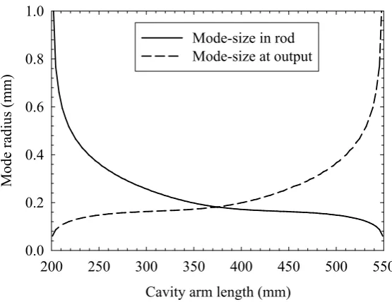
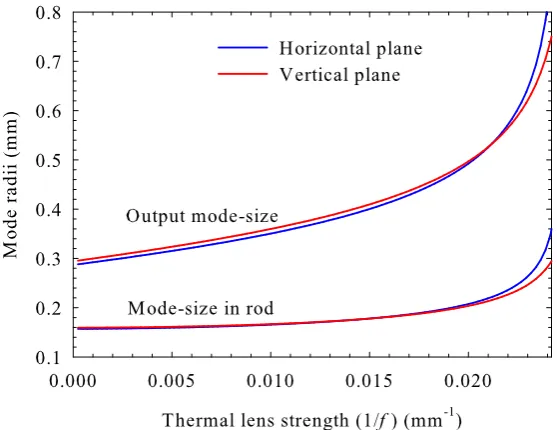
de-signing the resonator in this system by modelling of the resonator mode and varying relevant parameters is explained. The resonator design used in the oscillator is then described and the sensitivity of its calculated mode size to changes in various parameters such as mirror spacings and thermal lens focal length in the gain medium is shown. The experimental results of the oscillator performance characteristics are then presented and discussed.
In order to formulate an appropriate amplifier design strategy, the theory of laser amplification in end-pumped solid-state amplifiers is reviewed. Chapter 4 builds on the basic principles of amplification, initially in the small-signal limit and then extends this to account for saturation of the amplifier gain. An analytical approach is used to predict the effect of energy-transfer-upconversion on the small signal gain in an amplifier where the population inversion varies longitudinally, as in an end-pumped gain medium with a constant absorp-tion coefficient. An analysis of the saturated gain for a local area of the gain medium is reviewed, initially for a cw and then for a pulsed signal. This satu-rated gain formula for a pulsed signal is then used in a numerical integration to give the total gain for a Gaussian signal beam passing through an end-pumped gain medium where two simple approximations for the pump beam profile are compared. The effect of varying the ratio of the signal beam size to the pump beam size is explored and the optimisation of this overlap ratio with regard to maximising the gain is discussed. A simplified analysis of the degradation in beam quality, caused by aberrated thermal lensing, follows which is then used to extend the numerical model to make predictions of the brightness scaling potential of an amplifier. Finally the chapter discusses the use of multiple am-plifier stages and multiple pass amam-plifiers as a route for further power scaling
In Chapter 5, many of the principles from Chapter 4 are brought together to form a multi-stage Nd:YVO4 amplifier design where the seed laser is the
mode-locked laser described in Chapter 3. The applications of the MOPA system, particularly for non-linear frequency conversion are discussed. The main issues relevant to the design are explained and strategies for cooling the Nd:YVO4 crystals and relay-imaging the signal and pump beams from one
appara-tus used, are explained. The method of beam shaping and fibre-coupling of the diode pump sources, used to pump the amplifier chain, is detailed and a generic double-rod amplifier design used in the three amplifier stages is de-scribed. An experimental approach for finding the optimum signal beam size for the first amplifier stage is then presented. The results from this are com-pared to the theory and used to choose the parameters for the subsequent am-plifier stages. The final design and experimental set-up of the amam-plifier chain is then presented and the performance in cw mode, and then mode-locked mode, is discussed. The influence of the non-uniform radial gain profile is found to have a significant effect on the on the signal beam profile, leading to degradation in beam quality. The use of an acousto-optic modulator (AOM) to gate the amplifier input and allow pulsed operation is also described as a means to increase the peak power. The experimental results of the amplifier in pulsed mode are then presented for a range of operating regimes and the performance and potential applications of the source are discussed.
The use of the amplifier system described in Chapter 5 with other seed lasers is then considered. In Chapter 6, the use of the amplifier system to amplify the output from a single-frequency cw Nd:YVO4 oscillator is described and
the applications of such a source are discussed. The principles and meth-ods of achieving single-axial-mode (single-frequency) oscillation are explained and ways to suppress the problematic axial-mode-hopping are described. A single-frequency Nd:YVO4 oscillator, which was built, is described and its
performance characteristics are presented. The experimental results for the single-frequency MOPA system are then presented and discussed, initially in cw mode, and then in pulsed mode applying the same method as used for the mode-locked MOPA. A further development is also presented which uses analogue operation of the AOM to achieve effective pulse shaping of the input pulses to the amplifier, which can compensate for the temporal pulse distortion caused by the amplifier thus achieving a more desirable output pulse shape.
1.4
References
[1] Hollemann, G., Braun, B., Dorsch, F., Hennig, P., Heist, P., Kraus, U., Kutschki, U.and Voelckel, H., RGB lasers for projection displays, Proceed-ings: SPIE, Vol. 3954, pp. 140–151, 2000.
[2] Maiman, T. H.,Stimulated Optical Radiation in Ruby, Nature, Vol. 187, No. 4736, pp. 493–494, 1960.
[3] Newman, R.,Excitation of the Nd3+ fluorescence in CaWO
4 by recombination
radiation in GaAs, Journal of Applied Physics, Vol. 34, No. 2, pp. 437, 1963.
[4] Keyes, R. J., Injection luminescent pumping of CaF2:U3+ with GaAs diode
lasers, Applied Physics Letters, Vol. 4, No. 3, pp. 50–52, 1964.
[5] Paschke, K., Sumpf, B., Dittmar, F.andErbert, G.,Nearly Diffraction Lim-ited 980-nm Tapered Diode Laser With an Output Power of 7.7 W, IEEE Journal of Selected Topics in Quantum Electronics, Vol. 11, No. 5, pp. 1223–1227, 2005.
[6] Koechner, W., Solid-State Laser Engineering, Springer, 5th edn., 1999.
[7] Amano, S.andMochizuki, T.,High Average and High Peak Brightness Slab Laser, IEEE Journal of Quantum Electronics, Vol. 37, No. 2, pp. 296–303, 2001.
[8] Minassian, A., Thompson, B. and Damzen, M. J., Ultrahigh-efficiency TEM00 diode-side-pumped Nd:YVO4 laser, Applied Physics B: Lasers and
Optics, Vol. 76, pp. 341–343, 2003.
[9] Minassian, A., Thompson, B. and Damzen, M. J., High-power TEM00
grazing-incidence Nd:YVO4 oscillators in single and multiple bounce
configu-rations, Optics Communications, Vol. 245, pp. 295–300, 2005.
[10] Chen, Y. F.,Design criteria for concentration optimization in scaling diode end-pumped lasers to high powers: influence of thermal fracture, IEEE Journal of Selected Topics in Quantum Electronics, Vol. 35, No. 2, pp. 234–239, 1999.
[11] Chen, Y. F., Kao, C. F., Huang, T. M., Wang, C. L. and Wang, S. C.,
Laser-Diode End-Pumped Lasers, IEEE Journal of Selected Topics in Quan-tum Electronics, Vol. 3, No. 1, pp. 29–34, 1997.
[12] Liao, Y., Miller, R. J. D.andArmstrong, M. R.,Pressure Tuning of Thermal Lensing for High-Power Scaling, Optics Letters, Vol. 24, No. 19, pp. 1343– 1345, 1999.
[13] Zhang, H., Chao, M., Gao, M., Zhang, L. and Yao, J., High Power Diode Single-End-Pumped Nd:YVO4 Laser, Optics and Laser Technology, Vol. 35,
pp. 445–449, 2003.
[14] Peng, X., Xu, L.and Asundi, A.,Power Scaling of Diode Pumped Nd:YVO4
Lasers, IEEE Journal of Quantum Electronics, Vol. 38, No. 9, pp. 1291–1299, 2002.
[15] Zhang, J., Quade, M., Du, K. M., Liao, Y., Falter, S., Baumann, M., Loosen, P.andPoprawe, R.,EfficientT EM00operation of Nd:YVO4laser and
end-pumped by fiber-coupled diode laser, Electronics Letters, Vol. 33, pp. 775– 777, 1997.
[16] Hodgson, N., Griswold, K. D., Jordan, W., Knapp, S. L., Peirce, A. A., Pohalski, C. C., Cheng, E. A., Cole, J., Dudley, D. R., Petersen, A. B.
andNighan, W. L.,High powerT EM00operation of diode-pumped solid state
lasers, Proceedings: SPIE, Vol. 3611, pp. 119–131, 1999.
[17] Shi, P., Li, D., Zhang, H., Wang, Y. and Du, K., An 110W Nd:YVO4
slab laser with high beam quality output, Optics Communications, Vol. 229, pp. 349–354, 2003.
[18] Tzuk, Y., Tal, A., Goldring, S., Glick, Y., Lebiush, E., Kaufman, G.and
Lavi, R.,Diamond cooling of high-power diode-pumped solid-state lasers, IEEE Journal of Quantum Electronics, Vol. 40, No. 3, pp. 262–269, 2004.
[19] Forget, S., Balembois, F., Georges, P.andDevilder, P. J.,A New 3D Mul-tipass amplifier Based on Nd:YAG or Nd:YVO4 crystals, Applied Physics B,
Vol. 75, pp. 481–485, 2002.
Journal of Selected Topics in Quantum Electronics, Vol. 11, No. 3, pp. 621– 625, 2005.
[21] Siebold, M., Hornung, M., Hein, J., Paunescu, G., Sauerbrey, R., Bergmann, T. and Hollemann, G., A high-average-power diode-pumped Nd:YVO4 regenerative laser amplifier for picosecond-pulses, Applied Physics
B: Lasers and Optics, Vol. 78, pp. 287–290, 2004.
[22] Pearce, S. and Ireland, C. L. M., Performance of a cw pumped Nd:YVO4
amplifier with kHz pulses, Optics and Laser Technology, Vol. 35, pp. 375– 379, 2003.
[23] Brignon, A., Feugnet, G., Huignard, J.-P. and Pochelle, J.-P., Compact Nd:YAG and Nd:YVO4 amplifiers end-pumped by a high-brightness stacked
ar-ray, IEEE Journal of Quantum Electronics, Vol. 34, No. 3, pp. 577–585, 1998.
[24] Snell, K., Lee, D. and Wall, K., Diode-pumped, High-Power cw and Mode-locked Nd:YLF Lasers, Advanced Solid State Photonics 2000. Technical Di-gest.
[25] Lee, D., Snell, K. J., Manni, J. G. and Wall, K. F., Diode-pumped, High-Power Nd:YLF and Nd:YVO4 Lasers, The Solid State and Diode Laser Tech-nology Review (SSDLTR), 2000.
[26] Snell, K., Lee, D.andManni, J.,High Average Power, High Repetition Rate Nd:YVO4 MOPA Laser System, CLEO 1999. Postdeadline Paper, CDP-1.
[27] Ostermeyer, M., Kappe, P., Menzel, R.andWulfmeyer, V.,Diode-pumped Nd:YAG master oscillator power amplifier with high pulse energy, excellent beam quality, and frequency-stabilized master oscillator as a basis for a next-generation lidar system, Applied Optics, Vol. 44, No. 4, pp. 582–590, 2005.
[28] Kracht, D., Wilhelm, R., Frede, M., Fallnich, C., Seifert, F., Willke, B.and
Danzmann, K., High Power Single-Frequency Laser for Gravitational Wave Detection, Advanced Solid State Photonics 2006. Technical Digest, WE1.
system, OSA Trends in Optics and Photonics, Vol. 26 Advanced Solid State Photonics, pp. 216–221, 1999.
[30] Xi, W.-Q., Zhao, J.-Y. and Zhang, K.-S., A high-power continuous-wave laser-diode end-pumped Nd:YVO4 Laser of single-frequency operation, Chinese
Physics Letters, Vol. 22, No. 5, pp. 1144–1147, 2005.
[31] Schulz, B., Frede, M., Wilhelm, R. and Kracht, D., High Power End-Pumped Nd:YVO4 Amplifier, Advanced Solid State Photonics 2006.
Tech-nical Digest, WB15.
[32] Musgrave, I. O., Study of the Physics of Power Scaling of End-Pumped Solid-State Laser Sources based on Nd:YVO4, Ph.D. thesis,
Power Scaling in Solid-State Lasers
and Amplifiers
2.1
Introduction
’Solid-state lasers’describes all lasers in which the host medium for the active laser ion is either a crystal, a glass or a ceramic. Power scaling of solid-state lasers and amplifiers is a field that dates back to the birth of lasers in the 1960s. Kogelnik, 1966 [1] laid down the basic tools required for designing optical sys-tems and resonators. Over the years, as new solid-state materials and new pumping techniques have become available, the average output powers at-tainable have increased from milliWatts to&10 kilowatts [2]. This has largely been due to the development of high brightness laser diode bars and stacked diode arrays used to pump the materials. Pump powers of many kilowatts are now attainable in the 780-980nm wavelength region at relatively low cost. The main factors affecting the maximum power output of solid-state lasers are the maximum available power and spectral brightness of the pump source and the efficiency of the laser oscillator which in turn is governed by the losses in the cavity; the choice and quality of the laser crystal used and problems caused by heat generation in the laser crystal. The development of high power pump sources, high quality laser materials and low loss optical components has meant that the main challenges in power scaling today are dominated by management of thermal effects in the gain medium.
solid-state lasers and amplifiers with particular emphasis on end-pumped sys-tems. The relative merits of different laser host materials are discussed with regard to power scaling and the reason for choosing Nd:YVO4 in our system
is explained. Choice of pump source and pumping geometry and detrimental thermal effects in the gain medium are described, and various ways of min-imising these effects are discussed.
2.2
The Solid-State Laser
At low power levels, conventional solid-state lasers, which use well known host materials, have been well understood for many years. Their performance can be predicted reasonably successfully using some simple principles and analysis.
2.2.1
The Four-Level Laser Scheme
Laser Transition 1064 nm
Non-radiative decay
Non-radiative decay
Pump Transition 808 nm Pump Band (3)
Upper Laser Level (2) (Metastable Level)
Lower Laser Level (1)
Ground State (0)
Figure 2.1: Energy level diagram for a four level laser
a long lifetime,τ21, which means that a population inversion can be achieved
and hence laser action can take place. An ion in the metastable level will decay by spontaneous or stimulated emission of a photon to the lower laser level (labelled 1). Unlike in a three-level system, where the lower laser level is the same or close to the ground state, the lower laser level in a four-level system is significantly higher than the ground state and has a fast decay lifetimeτ10to
the ground state and therefore it remains essentially unpopulated.
2.2.2
The Laser Oscillator
Figure 2.2: A simple solid-state laser oscillator.
expres-sions for the threshold pump power and slope efficiency for a simple oscillator are shown in the next section.
The circulating laser field, within the cavity, is known as the laser mode and in general it contains a number of transverse and longitudinal oscillating modes. The modes which a resonator can support depends on the spacings, curvatures and alignment of the mirrors as well as on the gain distribution in the active medium and aperture effects caused by any of the optical components. It is normally desirable to operate a laser in the fundamental (TEM00) transverse
mode, since this offers the lowest possible divergence and hence the highest brightness beam. Indeed, measurement of the beam-size and divergence of a laser beam is used to determine the beam quality as explained in Section 2.2.5. The design of optical resonators based on modelling of Gaussian beam propagation is explained in Chapter 3.
The longitudinal modes of a resonator are present at regular frequency inter-vals, separated by the axial mode spacing∆ν which is equal to:
∆ν= c 2lc
, (2.1)
wherelcis the effective cavity length. The number of axial modes that actually
2.2.3
Threshold and Slope Efficiency
The most important measurable parameters that can be predicted analytically for a laser, are the threshold pump power Pp,th and output power Pout from
which the slope efficiency ηs can be deduced. For the simple case of an
end-pumped oscillator, with Gaussian intensity distributions for the pump and laser mode, the approximate expressions for Pp,th and ηs can be derived
us-ing a simplified rate equation approach [3]. The resultus-ing expressions are [4]:
Pp,th =
πhνP(L+T)(wp2+wl2)
4σ21τfηqηabs
(2.2)
and
ηs=
T L+T
νl
νp
ηabsηqηP L, (2.3)
whereνLandνP are laser and pump frequencies respectively,wlandwpare the
average laser and pump spot sizes in the crystal respectively, L is the cavity loss,T the output coupler transmission (L+T 1), σ21 is the laser transition
cross section,τf the fluorescence lifetime,ηqis the pumping quantum efficiency
(the fraction of pump photons which reach the meta-stable state), ηabs ≈ 1−
exp(−αplg)is the total fraction of pump power absorbed over the length of gain
mediumlg,αpis the absorption coefficient for the pump andηP L is an effective
spatial overlap factor for pump beam and laser mode given by [4] as:
ηP L =
wl2(wl2+ 2wp2)
(wl2+wp2)2
. (2.4)
This is valid in the low power regime where I/Isat 1, but ηP L → 1 for
the high power regime I/Isat 1 where Isat = hνl/σ21τf is the saturation
intensity. This expression takes into account the spatial and axial distribution of both the laser mode and the pump beam (assuming that the spot sizes are approximately constant over the length of the gain medium) and results in an effective overlap factor ofηP L = 0.75, for matched laser and pump beam sizes
(wl=wp), in contrast to a plane-wave approximation which givesηP L = 1.
2.2.4
Laser Amplifiers
amplifier or chain of amplifiers to form a master-oscillator-power-amplifier (MOPA). The amplifiers may or may not have the same basic geometry as the master-oscillator, but in the simple case of an end-pumped system the ampli-fier can consist of an end-pumped laser rod through which the laser signal is coupled via a dichroic mirror.
The total gain of a laser signal through an amplifier depends on a number of material, geometrical and optical parameters. However, if we consider the simple case of single-pass amplification of a laser signal passing through an inverted gain medium, the gain for a very small signal can be predicted ana-lytically. The total small signal gainG0, is the gain through the amplifier for a
signal intensity small enough not to significantly deplete the upper state pop-ulation. It is given by the expression
G0 = exp(g0l), (2.5)
wherelis the length of active medium traversed and for a 4-level transition,g0
is the small signal gain per unit length given by
g0 =σ21n2, (2.6)
wheren2 is the unsaturated upper state population density. A similar
expres-sion to equation (2.5) can also be used for the saturated gainGifn2 is replaced
with the saturated upper state population density.
In the small signal regime, a continuous laser signal passing through a medium with uniform upper state population density, which does not vary in the prop-agation direction, will grow in power exponentially with distance z through the medium. However, for a larger signal intensity a significant number of excited atoms decay by stimulated emission and, since gain is proportional to the number of excited atoms, the gain is thus reduced and the amplifier is said to be saturated. In the highly saturated regime, the gain becomes low (g0l 1)
and hence
exp(g0l)'1 +g0l, (2.7)
2.2.5
The
M
2Parameter
TheM2 parameter is a measure of the beam propagation factor orbeam quality
of a laser beam. Beams with good beam quality can propagate with low di-vergence when collimated and can also be focused down to small spot-sizes. For a beam propagating though a medium with uniform refractive index and through ideal lenses and mirrors, theM2parameter remains an invariant
prop-erty of the beam. A TEM00beam has the best theoretical beam quality possible
and its M2 parameter is equal to 1. Such beams have pure Gaussian
inten-sity distributions for all propagation distances. All other beams haveM2 >1. TheM2parameter is commonly referred to as the number of times diffraction-limited a particular beam is.
TheM2 parameter is determined by measuring the beam radius as a function of the propagation distance in the region close to a focal point (beam waist). For a beam propagating along thez-axis, theM2 value is normally measured
in thexandyplanes independently to allow for beams which are not cylindri-cally symmetric. In order to obtain accurateM2values the beam radius should
be measured using the second moment or variance method [5, 6] whereby:
σ2x= 1
P
Z
y Z
x
x2I(x, y)dxdy, (2.8)
wherexis the distance from the optic axis,I(x, y)is local intensity andP is the total power given by:
P =
Z
y Z
x
I(x, y)dxdy. (2.9)
The beam radiuswxis related to the standard deviationσx by the relation:
wx = 2σx. (2.10)
Figure 2.3 shows the beam radius for a beam propagating in the focal region. The the main parameters of interest for a beam waist are labelled. The beam sizew(z)and wavefront radius of curvatureR(z)as a function of the propaga-tion distancezcan be expressed as follows [3]:
w(z) =w0
s
1 +
M2λz
nπw2 0
2
Figure 2.3: Laser beam size versus propagation distance. z0 is the
Rayleigh range over which the beam expands to√2times the min-imum waist w0. 2z0 is known as the confocal parameter, θ is the
far field divergence angle and w(z)and R(z) are the spot size and wavefront radius of curvature respectively, as a function of propa-gation distancez.
R(z) = z
"
1 +
nπw20 M2λz
2#
. (2.12)
These can be reduced to give an expression for the Rayleigh range z0 over
which the beam expands to√2times the minimum waist size:
z0 =
nπw2 0
M2λ, (2.13)
and the far field divergence angleθcan be given by:
θ= M
2λ
nπw0
. (2.14)
Equations (2.13) and (2.14) are extremely useful for estimating the beam qual-ity and minimum spot sizes of laser beams in many situations.
2.3
Heat Deposition in the Gain Medium
2.3.1
The Quantum Defect
The quantum defect is simply the fractional difference in energy between the lasing photons and the pump photon. In terms of energy level transitions, the relaxation from the pump band to the upper laser level and from the lower laser level to the ground state are all thermal in the form of phonon emission. This means that the quantum defectQD can be expressed as:
QD = Ep−El
Ep
= 1−λp
λl
= 1− νl
νp
, (2.15)
where Ep and El are the pump and laser photon energies respectively and
λp, νp and λl, νl are the pump and laser wavelengths and frequencies
respec-tively, since the photon energy is inversely proportional to the wavelength. It is easy to see why using a laser transition, where the pump wavelength is close to the lasing wavelength is favourable since the quantum defect heating will be lower. Specialised lasers with quantum defects as low as 2.9% have been reported [7]. In general however, other factors such as the energy levels of strongest pump absorption and preferential lasing wavelengths are often more important when high output power and high efficiency is required.
2.3.2
Lifetime Quenching
2.3.2.1 Energy-Transfer-Upconversion
Figure 2.4: Schematic of Energy Transfer Upconversion
Energy-transfer-upconversion (ETU) occurs when two neighboring excited ions, a donor and an acceptor, exchange energy. Energy is transferred from donor to acceptor and consequently the acceptor is excited to a higher energy level whilst the donor ends up in a lower lying level. The particular levels that the donor and acceptor end up in depends on the possible transitions of the mate-rial. The result however is generally the same: the acceptor decays back to the upper laser level and the donor decays to the ground state. These decay pro-cesses can be radiative or non-radiative, or a combination of both, depending on the material. ETU essentially converts two excited ions into one excited ion and extra heat, as shown in Figure 2.4. The relative influence of ETU on the up-per state population depends on the upconversion parameter (W) of the laser material, and the number density (N2) of excited ions in the laser medium,
such that the rate of change of the number density with time is given by [8]:
dN2
dt =R− N2
τf
−W N22. (2.16)
The two main factors effecting N2, that can be controlled when designing a
2.3.2.2 Excited State Absorption
Phonon emission
Figure 2.5: Schematic of Excited State Absorption
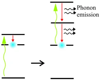
Excited state absorption is another process which can reduce the efficiency of a laser and lead to additional heating. In this case an ion in the upper laser level absorbs another pump photon, as shown in Figure 2.5, or a laser photon and is raised to a higher energy level before decaying by non-radiative transitions back to the upper laser level. The likelihood of ESA causing an appreciable effect on the performance of the laser depends on the relative cross sections of the ESA transition and stimulated emission [9].
[image:36.595.234.403.133.268.2]2.3.2.3 Cross Relaxation
Figure 2.6: Schematic of Cross Relaxation
2.4
Nd:YVO
4as a Laser Medium
Nd3+ was the first trivalent rare earth ion to be used in a laser. The most
com-mon host materials are Yttrium Aluminium Garnet (Y3Al5O12 or YAG),
Yt-trium Orthovanadate (YVO4 ), Yttrium Lithium Fluoride (YLiF4 or YLF) and
glass. Nd:YAG was the first to become widely used, and for many years, was one of the most efficient solid-state laser materials. Stimulated emission has since been achieved in over 100 host materials [3]. Nd:YVO4 was first
pro-posed for use as a laser material by O’Connor in 1966 [10], however it took until 1987 for the optical quality of the crystals to become good enough to be comparable to Nd:YAG for efficiency [11].
The energy level structure of the Nd3+ ion allows pumping at around 808 nm
to cause excitation to the4F
5/2/2H3/2 manifold, from where it rapidly relaxes
down to the metastable 4F
3/2 level. The dominant lasing transition is from
the 4F
3/2 level to the4I11/2 level and weaker lasing transitions are also
possi-ble from the metastapossi-ble level to the 4I
9/2 and 4I13/2 levels. The exact energy
or wavelength of these transitions varies a little between host materials but in Nd:YVO4 these three laser transitions correspond to wavelengths 1064 nm,
914 nm and 1342 nm respectively. Lasers with an output at 1342 or 914 can be made with relative ease [12], however the 1064 line provides potentially the highest yield of photons by stimulated emission due to its higher emis-sion cross section. The 914 transition does, however, have the advantage of a lower quantum defect. The energy level structure for Nd:YVO4 , including
all the important transitions, is shown in Figure 2.7. The cross sections for ESA and cross relaxation in Nd:YVO4 are relatively low so they can normally
be neglected, however ETU can be quite significant in some situations, that are discussed later in this thesis. The energy level structure for Nd3+ remains
E
ne
rgy
(c
m
-1)
0 5000 10000 15000 20000 25000 30000 4 4 2 2 24 2 2
2 2 2 4 2 2 4 2 4 4 4 4 4 4 D D D P D
G + G + K
G + K
G G H F F , H F F I I I I 1/2 3/2 5/2 1/2 3/2 9/2 11/2 9/2 13/2 7/2 5/2 11/2 9/2 7/2 9/2 5/2 3/2 15/2 13/2 11/2 9/2 4 S3/2
914nm 1064nm 1342nm ~1890nm
808nm
~808nm
~1890nm ~1342nm ~1064nm ~914nm
Peak absor ptio n tran sitio n Fluor esce nce tran sitio ns Ener gyT ran sfer Upc onve rsio n Exc ited State Abs orptio n ofpu mp rad iatio n Cros sR ela xatio n
Figure 2.7: Diagram showing (to scale) the energy level structure for Nd3+ in a YVO
4 host crystal. The main transitions are shown,
Properties Nd:YVO4 Nd:YAG Nd:YLF
Laser Wavelength (λl) (nm) 1064 1064 1047 (π)
1053 (σ) Peak Absorption Wavelength (λp) (nm) 808 808 792 (π)
797 (σ) Stimulated emission cross section (σ21) 25 (π) 2.8 1.8 (π)
(×10−19cm2) 7 (σ) 1.2 (σ)
Fluorescence lifetime (τf) (µs) 90 230 485
Linewidth (FWHM) (∆λ) (nm) 0.96 0.51 1.47 Peak absorption coefficient (αp) 31.4 (π) 7 10.8 (π)
(cm−1) 9.2 (σ) 3.59 (σ)
Absorption bandwidth(nm) 15.7 2.5 4.0 (@792nm) 3.2 (@797nm) Thermal Conductivity (Kc) (W m−1K−1) 5 14 6.3
Thermo-optical coefficient (dn/dT) 8.5 7.3 -4.3 (π)
(×10−6K−1) 3.0 -2.0 (σ)
Thermal fracture limit (F) (W cm−1) 57.6 94.8 22
Defined as wavelength range where 75% of pump power is absorbed in a 5mm thick crystal
Table 2.1: Optical and thermal properties of Nd:YVO4 compared to
Nd:YAG and Nd:YLF for 1% Nd doping concentration. Data from [3, 14, 15].
Nd:YVO4 and Nd:YLF are naturally birefringent so some of the properties
dif-fer between the extraordinary (c) axis and the ordinary (a) axis, which corre-spond to π andσ polarisations respectively. Normally in Nd:YVO4 , only the
cdirection is used because σ21 is much higher in this direction and therefore
the laser output is alwaysπ polarised. In Nd:YLF,σ21 in the two orientations
does not differ by so much so theπ polarisation can be used to generate 1047 nm radiation and theσpolarisation can be used to generate 1053nm radiation. Nd:YAG is isotropic so stimulated emission does not favour a particular po-larisation. Generating polarised output in a Nd:YAG laser requires the use of polarisation discriminating elements.
As shown in Table 2.4, Nd:YVO4has a much higher stimulated emission cross
section and consequently a higher σ21τf product than Nd:YAG and Nd:YLF.
From equations (2.2) and (2.3) we can see that this leads to a relatively low threshold and high slope efficiency assuming all other parameters are the same. Another important feature is that Nd:YVO4 has a stronger absorption
wavelength. The pump absorption coefficient in the π direction is more than four times that of Nd:YAG and three times that of Nd:YLF. This means that shorter laser crystals can be used to achieve the same absorption efficiency. This is advantageous when end-pumping with laser diodes because focusing them to small spot sizes implies having a short Rayleigh range due to their relatively poor beam quality. However, the associated high thermal loading density means that it is normally necessary to reduce the Nd3+ doping
con-centration somewhat to increase the absorption length. This can still be ad-vantageous because it reduces the impact of ETU.
While Nd:YVO4 has very favourable optical properties, its thermal properties
can be considered to be a little worse than Nd:YAG and Nd:YLF. While Nd:YLF has the lowest fracture limit and only slightly higher thermal conductivity than Nd:YVO4 , its resistance to thermal lensing effects are good. Unusually, it has
a low and negative thermo-optical coefficient which means that a weak neg-ative thermal lens is produced by intense end-pumping. Both Nd:YVO4 and
Nd:YAG produce positive thermal lenses under intense diode end-pumping. Nd:YAG has the highest thermal conductivity and the highest fracture limit, however it does suffer from thermal stress induced birefringence. Nd:YVO4
has around one third the thermal conductivity of Nd:YAG and less than two thirds the fracture limit. The additional properties of the thermal expansion coefficient and the stress-optic coefficient are also important when considering the thermal lensing behaviour of these materials but were unavailable to in-clude in Table 2.4. The axial temperature increase, caused by end-pumping, can cause thermal expansion resulting in end-face bulging which forms a posi-tive thermal lens. For Nd:YAG and Nd:YVO4this increases the overall thermal
lens strength while in Nd:YLF it acts to partially compensate for the negative thermal lens due to its negative thermo-optical coefficient. Thermal expansion also causes an associated stress distribution within the gain medium which leads to further modification of the refractive index. The stress-optic coeffi-cient describes this change in refractive index with respect to the stress in the material. In Nd:YAG this is more important because it suffers from stress in-duced birefringence, where in Nd:YVO4and Nd:YLF their stress induced
leading to additional heating in all Nd3+ doped materials due to a higher
in-teraction cross section than ESA and cross relaxation. Particular care is needed to avoid fracture under non-lasing or unsaturated conditions when the rate of ETU becomes higher.
2.5
Thermal Effects
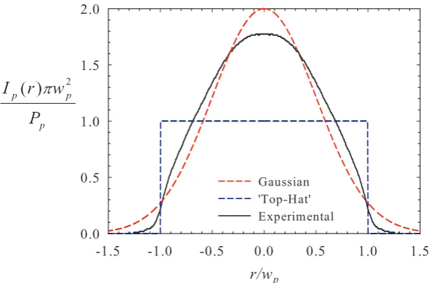
There are a number of mechanisms that cause heat deposition in a laser medium under intense optical pumping. In particular, end-pumping laser materials with high power diode sources can lead to large amounts of heat being gen-erated. Active cooling of the gain medium is essential in most high power lasers and amplifiers to remove this unwanted heat. For end-pumped rods, edge-cooling of the gain medium is usually the only option and this can be achieved by mounting the rod in a water-cooled copper heat sink. This means that most of the heat flow is in the radial direction causing radial temperature gradients which generally causes a number of undesirable effects. The temper-ature distribution in an end-pumped edge-cooled laser rod can be described by an exponential decay in the z-direction in correlation with the exponential decay in absorbed pump power with propagation distance, and an approxi-mately quadratic radial dependence within the pump beam radius [16] and an exponential radial dependence outside the pump beam radius (assuming a ‘top-hat’ pump beam profile). Figure 2.8 shows, graphically, an estimate of the normalised temperature increase∆T for a typical rod of dimensions 3mm diameter and 10mm length, caused by end-pumping with a pump beam of radius 0.3mm and a ‘top-hat’ profile.
2.5.1
Thermal Stress Induced Birefringence
be-Figure 2.8: Estimated temperature distribution in a typical end-pumped laser rod with a ‘top-hat’ pump beam profile (shown by red line).
comes compressed in the radial direction and under tension in the tangential direction. The resulting birefringence causes radial and azimuthal dependent retardation for beams passing through the laser rod. A polarised incoming laser beam can therefore become depolarised on transit through the mate-rial. Laser materials which have natural linear birefringence, like crystalline Nd:YVO4 and Nd:YLF, avoid this problem because the stress induced
birefrin-gence is usually negligible compared to their natural birefrinbirefrin-gence. Also, their thermal expansion coefficients are usually different in their a and c-axes, so thermally induced stresses are higher in one direction. In isotropic gain me-dia like Nd:YAG and doped ceramics however, stress induced birefringence is a problem. In laser configurations, a Brewster-angled plate can be used to discriminate between two orthogonal polarisations to produce a linearly polarised output, however the loss due to depolarisation can become large at higher pump powers and additional compensating schemes are often re-quired [17]. This is a another very attractive reason for choosing Nd:YVO4 as
2.5.2
Aberrated Thermal Lensing
In addition to thermal stress induced changes in refractive index, the temper-ature change itself causes changes in refractive index. The change in refractive index with respect to temperature change is described by the thermo-optical coefficient dn/dT, included in Table 2.4. The combination of stress and tem-perature induced refractive index change leads to the effect of thermal lensing in the gain medium. This lensing is made worse still by the physical distor-tion of the end-faces of the laser rod caused by thermal expansion in an fect known as end-face bulging. The relative contribution of these three ef-fects on the overall thermal lens depends on the optical and thermo-mechanical properties of the gain medium but, in Nd:YAG for example, the refractive index variation with temperature accounts for over 80% of the ther-mal lens contribution [4]. An analytical expression for the temperature distri-bution in an edge-cooled end-pumped laser rod has been derived by solving the general steady state thermal transport equation, assuming no axial heat flow [18]:
∇ ·u(r, z) = Q(r, z), (2.17)
where u(r, z) is the heat flux, and Q(r, z) is the power per unit volume de-posited as heat in the laser crystal. Considering only the contribution to ther-mal lensing due to temperature dependence of refractive index this model can be used to predict the thermal lens focal length for an arbitrary pump beam intensity profileIp(r)[19]:
fth(r) =
2πKcr2
Pabsγ(dn/dT)s(r)
, (2.18)
where Kc is the thermal conductivity, Pabs is the total absorbed pump power,
γ is the fraction of absorbed pump power dissipated as heat and s(r) is the fraction of pump power contained within a disc of radiusrgiven by:
s(r) = 2π
Pp Z r
0
r0Ip(r0)dr0. (2.19)
implies a highly aberrated thermal lens which will cause severe degradation of laser beam quality.
More detailed discussions of the influence of the pump beam profile on the thermal lensing and thermal lens induced aberration and strategies for coping with it will follow later in this thesis.
2.5.3
Thermally-Induced Stress Fracture
Due to the high stresses that are produced by intense diode pumping, ther-mal stress fracture places an ultimate limit on how much pump power can be absorbed in a laser material. Stress fracture normally occurs when the tensile stress in the laser rod reaches the breaking stress of the material. Table 2.4 in-cludes the fracture limit in (W cm−1) for the three materials discussed. While
this provides a useful comparison for the materials under approximately the same conditions, several factors other than pump intensity need to be consid-ered to reduce the likelihood of stress fracture. These include the total pump power; the size and shape of the laser material; the doping concentration; the optical quality of the crystal and its dielectric coatings; the efficiency of the cooling mechanism and the temperature to which it is cooled. In practice, it can be difficult to account for all these factors but various techniques can be adopted to maximise the pump power that can be absorbed before thermal fracture occurs and thereby reduce other undesirable thermal effects as well.
2.6
Tackling Thermal Effects
2.6.1
Laser Architecture Alternatives
There have been a wide variety of laser architectures developed, aimed at ex-tending the power and brightness scalability of solid state lasers. One of the principal strategies for reducing thermal effects is to increase the ratio of cool-ing surface to pumped volume. Another approach that can be applied to a range of laser geometries is cryogenic cooling of the active medium [20]. The thermal properties of most laser materials have been shown to improve dra-matically at very low temperatures, such as that of liquid nitrogen. For ex-ample the thermal conductivity becomes much larger, making removal of heat much more efficient. Temperature gradients and therefore thermal effects can be made very small. The disadvantage however, is that the complexity be-comes prohibitively large for most laser systems. Not only does the cooling system itself add complexity, but also all components which are cooled to low temperature need to be placed in a partial vacuum to avoid problems with condensation. Some of the more popular architectures which can all be used in both laser and amplifier configurations are summarised as follows.
2.6.1.1 Side-Pumped Slab Lasers
The side-pumped slab laser uses a slab of the active medium which is cooled via its top and bottom surfaces which have the largest area. In this scheme, shown in 2.9, one or two of the remaining faces are pumped and the laser ra-diation is approximately orthogonal to the pump rara-diation. One particular advantage of side-pumping slabs like this is that the high aspect ratio of the pumping faces of the slab are ideally suited for pumping with high power diode bars which have a similarly high aspect ratio, as discussed in Section 2.7.2. This simplifies the design and means that very high efficiency of inci-dent pump power to available pump power can be achieved. One drawback of this technique, is that the pumped volume is generally not well matched to the laser mode. This implies that it can be difficult to achieve high extraction of stored energy. When a gain medium with a high absorption coefficient such as Nd:YVO4 is used, the inversion density is localised in the region closest to the
Figure 2.9: Single-bounce slab laser configuration with diode bar side-pumping
the laser and pump volumes is higher and hence the efficiency can be increased compared to a simple beam transit through the material. Moreover, one of the main attractions of this geometry is that the laser beam is inverted horizon-tally on reflection at the pumped face which means that the distortions, which result from the horizontal gain and temperature gradients, are equal and op-posite for each half of the transit through the material. This implies very good compensation for beam quality degradation since the horizontal distortions acquired on the input section of the transit are almost completely reversed on the output section. Another common technique for improving the extraction efficiency is to allow the laser beam to make multiple passes through the ma-terial, each one accessing a different region of the slab, as shown in Figure 2.10 (b). From a thermal point of view, slab lasers have some favourable properties such as large cooling area to pump volume ratio, and the pump distribution is more uniform than in end-pumped systems leading to reduced thermal lens-ing. However, due to the lack of cylindrical symmetry, the thermal lensing effects, when they do occur, can be more problematic with the strong astigma-tism of the thermal lens being one example.
2.6.1.2 End-Pumped Rod Lasers
The laser and amplifier systems described later in this thesis are all based on end-pumped rod geometries. In this scheme the pump and laser beams are collinear and the heat removal is through the sides of the rod, as shown in Figure 2.11.
Figure 2.11: End-pumped rod laser configuration
The advantage of this scheme, compared to side pumping for example, is that the pump and laser beams can be very well matched spatially to allow effi-cient extraction of the stored energy and easy selection of TEM00 modes in a
systems have incorporated undoped end-caps on the laser rods [16, 21]. This implies that pump radiation is only absorbed in the doped region away from the surface. The main advantage of this is to eliminate end-face bulging by minimising the temperature rise at the surface.
2.6.1.3 Thin-Disc Lasers
Figure 2.12: An example of a thin-disc laser set-up
One laser geometry, which has been proved to be very successful for power scaling, is the thin-disc laser. In this scheme, shown in Figure 2.12, a thin disc of the gain medium, of a few hundredµm thickness, which is HR coated on the back surface for pump and laser radiation and AR coated on the front surface, is bonded to a water cooled heat sink. A laser resonator is formed between a curved output coupler and the HR surface of the disc. In this scheme, the cooling surface is large compared to the pumped volume so high output power can be extracted from a small volume. Since the back surface of the disc is cooled, the heat flux and the laser beam axis are collinear to each other. As a consequence, thermal lensing effects are dramatically reduced. Due to the very short interaction length in the gain medium, large doping concentrations are required as well as multiple passes of the pump radiation in order to achieve high absorption efficiency. Using this kind of system with Yb:YAG as the gain medium, cw laser powers of up to 1kW have been achieved [22]. Nd3+ based
lasers materials have a larger quantum defect so thermal loading is typically almost three times higher than in Yb:YAG. One of the highest reported output powers for a thin disc laser based on Nd3+ was a Nd:GdVO
4 thin-disc laser
thermal effects in the gain medium which degrade the beam quality. Thermal distortions stem mainly from the bending of the crystal due to the difference in expansion of its front and back surfaces with additional aberrations resulting from a radial temperature gradient at the edge of the pumped area.
2.6.1.4 Fiber Lasers
Figure 2.13: Double-clad fibre laser
not, in general, maintain the polarisation state of ingoing light. Additional complexity in fabrication is required to produce polarisation maintaining fi-bres. Moreover, in pulsed operation, the high laser intensities in the fibre core can lead to a number of undesirable nonlinear effects. The most common are Stimulated-Brillouin-Scattering (SBS) and Stimulated-Raman-Scattering (SRS) whereby some of the power becomes backscattered or forward-scattered by acoustic or optical phonons respectively [24]. Some problems can also arise from self-phase modulation caused by the Kerr nonlinearity. Increasing the core size of the fibre is necessary to reduce the nonlinear effects, but this makes single-mode operation more difficult to achieve.
2.6.2
Phase Conjugation
Figure 2.14: Schematic of wavefront distortion through two passes of an aberrated medium with reflection from (a) a conventional mir-ror and (b) a phase conjugate mirmir-ror