ARCING HIGH IMPEDANCE FAULT DETECTION USING REAL CODED
GENETIC ALGORITHM
Naser Zamanan Jan Sykulski A. K. Al-Othman
School of Electronics &
Computer Science School of Electronics & Computer Science Dept. Electrical Engineering University of Southampton University of Southampton College of Technological Studies
U.K. U.K. Kuwait
[email protected] [email protected] [email protected]
ABSTRACT
Safety and reliability are two of the most important aspects of electric power supply systems. Sensitivity and robustness to detect and isolate faults can influence the safety and reliability of such systems. Overcurrent relays are generally used to protect the high voltage feeders in distribution systems. Downed conductors, tree branches touching conductors, and failing insulators often cause high-impedance faults in overhead distribution systems. The levels of currents of these faults are often much smaller than detection thresholds of traditional ground fault detection devices, thus reliable detection of these high impedance faults is a real challenge. With modern signal processing techniques, special hardware and software can be used to significantly improve the reliability of detection of certain types of faults. This paper presents a new method for detecting High Impedance Faults (HIF) in distribution systems using real coded genetic algorithm (RCGA) to analyse the harmonics and phase angles of the fault current signals. The method is used to discriminate HIFs by identifying specific events that happen when a HIF occurs.
KEY WORDS
Downed power line, arcing high impedance fault, transient analysis, harmonics, real coded genetic algorithm.
1. Introduction
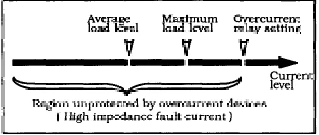
Detection of downed power lines is a long-standing problem to electric utilities. High impedance faults result in very low currents which are often not detectable by conventional overcurrnet relays. A HIF occurs, for example, when a conductor breaks and falls on a non-conducting surface such as asphalts road, sand, grass or a tree limb producing a very small current. These faults are difficult to detect when the impedance at the point of fault is high enough to limit the fault current to the region unprotected by conventional overcurrent devices (Fig. 1). When no solid return path for the current is available, the fault exhibits arcing phenomena; these faults are then referred to as “high impedance arcing faults”. HIFs are a dangerous phenomenon since risks of electric shocks are posed to the public and fire hazard also exist. It is
estimated that majority of electrically caused fires are due to arc type, hot neutral intermittent faults [1] .
[image:1.612.324.555.365.463.2]Therefore, the principal motivation in high impedance fault detection is not just system protection, but to improve safety. The threshold of overcurrnet relays must be set at a relatively high current level to prevent tripping by inrush currents thereby causing unnecessary service interruption. Most detection schemes involve the adjustment of the existing overcurrent protection to be more sensitive by lowering its setting. Such scheme have failed to operate in 32% of high impedance faults and lead to several unexpected service interruptions [1].
Fig. 1. Relation of high impedance fault current to overcurrent device settings
In the past two decades many techniques have been proposed to improve the detection of HIFs in power distribution systems, and recently the utilities have intensified research programs searching for more efficient protection against this type of a fault.
HIFs [11, 12], as well as a wavelet transform used for digital signal processing of HIF signals [13, 14].
This paper describes a novel digital technique suitable for detecting high impedance faults. A Real Coded Genetic Algorithm (RCGA) has been employed to analyse the harmonics and phase angles of high impedance fault current signals. The method is used to discriminate HIFs based on specific events that happen during the occurrence of a HIF.
2. Arc current Nature
An arc is defined as a luminous electrical discharge flowing through a gas between two electrodes. In the case of an arcing HIF, when an energized conductor touches the ground, the electric contact is not solid. Due to the existence of air between the ground and the conductor, the high potential difference across a short distance excites the appearance of an arc.
[image:2.612.328.538.453.717.2]Many authors have worked on the theory and dynamics of voltages and currents in an electric arc, most such studies are experimentally based. In [15] and later in [16] a model explaining the phenomenon using a spark gap was proposed. This air gap will not conduct till the applied voltage reaches the breakdown point. Then the current flows and reaches a maximum when the applied voltage equals the arc voltage. After that, the arc current decreases and becomes zero, i.e. the arc is extinguished. When extinction occurs, the arc requires a potential, known as restrike voltage, to reignite. This reignition will have the opposite polarity. This explains the typical voltage-current waveform of an arc shown in Fig. 2. Many electric models have been proposed describing arc behaviour as reviewed by [17].
Fig. 2.Electric arc voltage and current shapes
In the context of downed conductors, Russell [18] conducted stagedHIF tests studying dependencies of arc current magnitude on potential difference, gap distance, features of the grounding surface and environmental conditions of the grounding point. A high degree of random behaviour was observed due to impurities near the grounding point, heat from the arc that is intense enough to fuse substances and the evolution of different paths for current flow on surfaces.
2.1 HIF model
High impedance fault is a difficult case to model because most HIF phenomena involve arcing, which has not been
accurately modelled so far. Some previous researchers have reached a consensus that HIFs are nonlinear and asymmetric, and that modelling should include random and dynamic qualities of arcing. Emanuel et al [19] suggested two dc sources connected antiparallel with two diodes to simulate zero periods of arcing and asymmetry. Yu et al [20] used combinations of nonlinear resistors, while Wai et al [21] introduced a sophisticated TACS switch controlling the open/closed loop of a HIF to introduce nonlinearity and asymmetry. In this paper, a more dynamic and random HIF model is applied. It combines most of the advantages of the previous models proposed while remaining simple and universal; it was first put forward by the authors in [22] .
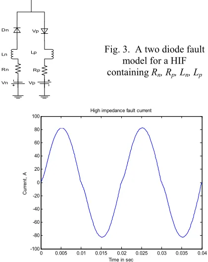
The high impedance fault model proposed in [22] is shown in Fig. 3 and includes two DC sources, Vp and Vn, which represent the arcing voltage of air in soil and/or between trees and the distribution line; two resistances, Rp and Rn, between diodes, which represent the resistance of trees and/or the earth resistance; and – since most
observed arcs occur in highly inductive circuits [23] –
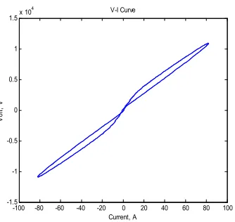
two inductances, Lp and Ln, added to the circuit. The effect of the inductances leads to the nonlinearity loop in the V-I curve and the desired asymmetrical shape for the HIF current. When the line voltage is greater than the positive DC voltage Vp, the fault current starts flowing towards the ground. The fault current reverses backward from the ground when the line voltage is less than the negative DC voltage Vn. In the case when the line voltage is in between Vp and Vn, the line voltage is counter-balanced by Vp or Vn so that no fault current flows. As a direct result of the presented model the typical high impedance fault current and V-I curves were produced and are shown in Figures 4 and 5.
Vp Vp
Rp Dn
Vn Rn
Lp
Ln Fig. 3. A two diode fault model for a HIF containing Rn, Rp, Ln, Lp
0 0.005 0.01 0.015 0.02 0.025 0.03 0.035 0.04
-100 -80 -60 -40 -20 0 20 40 60 80 100
Time in sec
C
urre
nt
, A
High impedance fault current
[image:2.612.63.282.463.552.2]3. The harmonic model
A signal can be defined as a function that carries information, usually about a state or a procedure of a physical system. However, signals can be represented in several ways. Mathematically, a periodic and distorted signal can be suitably represented in terms of its fundamental frequency and harmonic components, expressed as a sum of sinusoidal waveforms referred to as the Fourier series. Each frequency is an integer multiple of the fundamental system frequency. In order to obtain an approximation of such waves, mathematical models are employed. Consider a current waveform with harmonic components, written as [24, 25]
) cos(
1 cos( )}
{ )
( ο ∑ ω φ ωο +φο
=Α +
+ Α
= m t
i fi fit fi
t
I (1)
where:
ο
Α is the fundamental current amplitude,
ο
ω is the power frequency,
fi
Α is the amplitude of the flicker current,
fi
ω is the flicker current frequency, m is the number of flicker models,
fi
φ is the phase angle of flicker current.
With only one flicker frequency this can be written as: ) 2 )( cos(
) 1 1 cos( 1 ) cos(
)
(t =Αο ωοt+φο +Α ωf t+φf ωοt+φο I
Given that ωοis known, the problem is now to find the
optimum values forΑο,φο,Α1,ωf1,φf1 using RCGA.
4. Genetic Algorithm
A genetic algorithm is a computational model that solves optimization problems by imitating genetic processes and the theory of evolution [26-28]. Solutions from a population are used to form a new population. This is motivated by the hope that the new population will be better than the old one. Solutions that will form new solutions are selected according to their fitness: the more suitable they are, the more chances they have to reproduce. This is repeated until some condition (for
example a number of generations or an improvement in the best solution) is satisfied. In the traditional GA, all the variables of interest must first be encoded as binary digits (genes) forming a string (chromosome). To minimize a function
f
(
x
1,
x
2,...,
x
k)
using GA, first, eachx
i iscoded as a binary or floating-point string of length m. Thus
] 01011 ... 11110 [
[image:3.612.65.232.53.211.2]... ... ... ...
] 11110 ... 00101 [ 2
] 01001 ... 10001 [ 1
= = =
xk x x
where {
x
1,
x
2,...,
x
k} is called a chromosome andx
iaregenes. Then three standard genetic operations, i.e. reproduction, crossover, and mutation are performed to produce a new generation [26-28]. Such procedures are repeated until the pre-specified number of generations is achieved, or the required accuracy is reached.
Other coding types have been considered, such as Real Coded Genetic Algorithms (RCGAs), which seem particularly natural when tackling optimization problems of parameters with variables in both continuous and discontinuous domains. In the Real Coded GAs, a chromosome is coded as a finite-length string of real numbers corresponding to the design variables. The RCGA is rigorous, precise, and efficient, because the floating point representation is conceptually close to the real design space. In addition, the string length reduces to the number of design variables. A comparative study conducted in [29] concluded that the Real Coded GAs outperform binary-coded GAs in optimization problems.
4.1 Fitness Function
A fitness function (FF) is one of the key elements of GAs as it determines whether a given potential solution will contribute its elements to a future generation through the reproduction process. The FF should be able to provide a good measure of the quality of the solution and should differentiate between the performance of different strings. In this study the fitness function is set to minimize the maximum individual error. The evaluation function is the function responsible for the determination of the fitness of each individual. Its objective is to evaluate the estimation error (e). The coded parameters are compared to the measured value in each time step I(t) to calculate the average error (e). We use the evaluation function as the sum of quadratic errors. The error at each time step can be calculated as
ei I
Ii(actual)− i(calculated)= for i=1,2,...m (3)
The quadratic error is calculated as
m i e Fsum
m
i∑
= =1 2
(4)
-100 -80 -60 -40 -20 0 20 40 60 80 100
-1.5 -1 -0.5 0 0.5 1 1.5x 10
4
Current, A
Vo
lt,
V
V-I Curve
5. Testing the algorithm
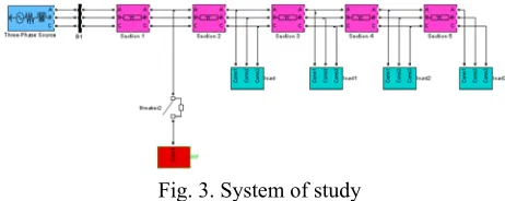
In this case a practical power system is simulated to demonstrate the ability of the Real Coded Genetic Algorithm to track harmonics during normal and abnormal conditions in a power system. The system is simulated using Simulink and SimPowerSystems block set. The simulated system is shown in Figure 3. A three-phase, 50 Hz, 11 kV power system transmitting power from a substation to an equivalent network through a 8 km transmission line. The voltage source is simulated with a Simplified Sim power systems voltage block. Universal transformer blocks are used to model the transformers. The transmission line is modelled as π
sections, where it is split in four 2 km lines connected between buses. A three-phase load is located at each end of the π section through a 1000 to 1600kVA 11/0.433 kV transformer. The load may be varied to simulate either balanced or unbalanced loading conditions. Voltages and currents are measured in a B1 block.
[image:4.612.349.534.157.386.2]In order to verify the proposed algorithm and assess its transient performance, a high impedance fault was applied to the system at the first section of the line.
Fig. 3. System of study
5.1 Detection criteria
A Real Coded Genetic Algorithm was used to analyze the harmonics of the current waveform. A decision whether there is a HIF is based on the existence of the 3rd and 5th
harmonics and the angle shift of the 3rd harmonic with
respect to the fundamental current.After many simulation tests a threshold has been specified for the harmonics and the angle shift to determine a HIF. For the 3rd and 5th
harmonics a 1% and a 0.5% of the fundamental current were set as threshold values, respectively. For the 3rd
harmonic angle, an angle shift threshold of 100 degrees with respect to fundamental current angle was set.
6. Testing and results
As may be seen in Table 1, before the HIF occurs, the load current is normal with no change in the phase angle and no harmonic currents. After the HIF has been applied there is an increase of 13.7 amps in the load current; this can be interpreted by the protection relay as a load increase instead of a fault, simply because the HIF does not draw sufficient current for the relay to act. In a normal fault, the current in the fault will be much greater than the relay setting, therefore the relay will react to the fault; in
the HIF case this will not happen because the setting in the relay is much less than the HIF current (see Fig. 1). During the existence of the HIF there is a noticeable change in the circuit harmonics. The existence of the 3rd
and 5th harmonics, plus the slight increase of load current
and the angle shift of the third harmonics with respect to fundamental current, together confirm the existence of the HIF, since these are the peculiar characteristics of a HIF.
harmonics and phase angle
Before HIF After HIF
1st 228.2235 242.0934
Θ1 0 0
2nd 0.0004 0
Θ2 0 0
3rd 0.0002 4.7901
Θ3 0 1.9322
4th 0.0003 2.2242
Θ4 0 0
5th 0.0001 1.4567
Θ5 0 3.4981
6th 0.0001 0
Θ6 0 0
7th 0 0.2469
Θ7 0 0
[image:4.612.52.283.332.424.2]DC transient 0 0
Table 1. Current harmonics and phase angles before and after high impedance fault
7. Conclusion
A new method for high impedance fault detection is proposed. The problem is formulated as an estimation task and a Real Coded Genetic Algorithm is used to solve this optimization problem. The method was successfully tested on tracking harmonics and current angles associated with HIF. The very accurate results obtained show that the proposed approach can be used as a very reliable method of identifying high impedance faults.
References
[1] A. M. Sharaf and S. I. Abu-Azab, "A smart relaying scheme for high impedance faults in distribution and utilization networks," Halifax, NS, Canada, 2000.
[2] C. G. Wester, "High impedance fault detection on distribution systems," presented at 1998 Rural Electric Power Conference Presented at 42nd Annual Conference, 26-28 April 1998, St. Louis, MO, USA, 1998.
[4] H. Calhoun, M. T. Bishop, C. H. Eichler, and R. E. Lee, "Development and testing of an electro-mechanical relay to detect fallen distribution conductors," IEEE Transactions on Power
Apparatus and Systems, vol. PAS-101, pp.
1643-50, 1982.
[5] B. D. Russell and R. P. Chinchali, "A digital signal processing algorithm for detecting arcing faults on power distribution feeders," IEEE Transactions on Power Delivery, vol. 4, pp. 132-40, 1989.
[6] Y. Sheng and S. M. Rovnyak, "Decision tree-based methodology for high impedance fault detection," IEEE Transactions on Power Delivery, vol. 19, pp. 533-536, 2004.
[7] A. Lazkano, J. Ruiz, L. A. Leturiondo, and E. Aramendi, "High impedance arcing fault detector for three-wire power distribution networks," Lemesos, Cyprus, 2000.
[8] M. El-Hami, "A distribution system fault location technique utilizing high frequency spectrum of fault current," Galway, Ireland, 1994.
[9] A. A. Girgis, W. Chang, and E. B. Makram, "Analysis of high-impedance fault generated signals using a Kalman filtering approach," IEEE
Transactions on Power Delivery, vol. 5, pp.
1714-24, 1990.
[10] A.-R. Sedighi, M.-R. Haghifam, and O. P. Malik, "Soft computing applications in high impedance fault detection in distribution systems," Electric Power Systems Research, vol. 76, pp. 136-144, 2005.
[11] T. M. Lai, L. A. Snider, E. Lo, C. H. Cheung, and K. W. Chan, "High impedance faults detection using artificial neural network," Hong Kong, China, 2003.
[12] H. Khorashadi-Zadeh, "A novel approach to detection high impedance faults using artificial neural network," Bristol, UK, 2004.
[13] A. R. Sedighi, M. R. Haghifam, O. P. Malik, and M. H. Ghassemian, "High impedance fault detection based on wavelet transform and statistical pattern recognition," IEEE
Transactions on Power Delivery, vol. 20, pp.
2414-21, 2005.
[14] K. Chul-Hwan, K. Hyun, K. Young-Hun, B. Sung-Hyun, R. K. Aggarwal, and A. T. Johns, "A novel fault-detection technique of high-impedance arcing faults in transmission lines using the wavelet transform," IEEE Transactions on Power Delivery, vol. 17, pp. 921-9, 2002. [15] R. H. Kaulinann and J. C. Page, "Arcing fault
protection for low-voltage," power distribution
systems- nature of the problem,” AIEE Trans,
pp. 160-167, June 1960.
[16] J. R. Dunki-Jacobs, "The effects of arcing ground faults on low-voltage system design,"
IEEE Transactions on Industry Applications,
vol. IA-8, pp. 223-30, 1972.
[17] T. Gammon and J. Matthews, "The historical evolution of arcing-fault models for low-voltage systems," Sparks, NV, USA, 1999.
[18] B. D. Russell, R. P. Chinchali, and C. J. Kim, "Behaviour of low frequency spectra during arcing fault and switching events," IEEE
Transactions on Power Delivery, vol. 3, pp.
1485-92, 1988.
[19] A. E. Emanuel, D. Cyganski, J. A. Orr, S. Shiller, and E. M. Gulachenski, "High impedance fault arcing on sandy soil in 15 kV distribution feeders: contributions to the evaluation of the low frequency spectrum," IEEE Transactions on Power Delivery, vol. 5, pp. 676-86, 1990.
[20] D. C. Yu and S. H. Khan, "An adaptive high and low impedance fault detection method," IEEE
Transactions on Power Delivery, vol. 9, pp.
1812-21, 1994.
[21] D. C. T. Wai and X. Yibin, "A novel technique for high impedance fault identification," IEEE
Transactions on Power Delivery, vol. 13, pp.
738-44, 1998.
[22] N. Zamanan and J. K. Sykulski, "Modelling arcing high impedances faults in relation to the physical processes in the electric arc," WSEAS
Transactions on Power Systems, vol. 1 (8), pp.
1507-1512, 2006.
[23] D. I. Jeerings and J. R. Linders, "Ground resistance-revisited," IEEE Transactions on Power Delivery, vol. 4, pp. 949-56, 1989.
[24] N. Zamanan, J. K. Sykulski, and A. K. Al-Othman, "Real Coded Genetic Algorithm Compared to the Classical Method of Fast Fourier Transform in Harmonics Analysis," presented at In Proceedings of 41st International Universities Power Engineering Conference, Newcastle upon Tyne, UK. , 2006.
[25] R. C. Dugan, M. F. McGranaghan, and H. W. Beaty, Electrical Power Systems Quality. United states: McGraw Hill, 1996.
[26] D. E. Goldberg, Genetic Algorithms in Search
Optimization and Machine Learning. Reading,
Ma: Addison Wesely, 1989.
[27] D. A. Coley, An introduction to Genetic
Algorithms For Scientists and Engineers: World
scientific, 1999.
[28] M. Mitchell, An introduction to Genetic Algorithms: MIT press, 1999.